CONTENTS OF THIS CHAPTER
This chapter covers the following topics:
- typical tool functions and benefits;
- tools through solution lifecycles;
- what’s in a name?
- evaluating tools;
- benefits and pitfalls of adopting tools.
INTRODUCTION
As the capabilities of computer-based software applications have evolved over the last few decades, so have the complexities of the software and its environment. Whereas it was once possible to develop a whole application using a pen-and-paper design, coded and built using a text editor and a command line compiler, it is difficult to imagine doing so now for even the simplest application.
During unit design, the code and build activities for the different run-time environments (including operating systems, application servers and client-side web-browsers) require specific combinations of static and dynamically-linked libraries of components and objects to be incorporated into the application specific source code. The interdependencies between all these elements are so complex that they are almost impossible to manage without the aid of tools.
This Introduction has so far focused on how development tools are essential at the point of coding software, but their use extends well before that into the realms of business analysis and requirements and beyond into testing, release management and even supporting and monitoring the software in operations.
TYPICAL TOOL FUNCTIONS AND BENEFITS
The benefits of using computer-aided tools over more primitive approaches such as pen and paper or whiteboard is not due to simplicity, cost or general availability. So what can computer-aided tools provide that, if using primitive tools, can be done manually, but not as efficiently?
Standardisation
The use of templates and specific notation and syntax is a critical element of any team-based activity such as developing and managing IT systems. This includes the use of forms for written documents and specific visual syntax for diagram notation.
Storage
Creating computer-based files rather than paper documents means that they can be stored and backed up electronically – either as electronic equivalents of paper documents or as elements within a tool’s repository. That repository could be as simple as a folder on a disk drive or a complex meta-model defining a tool-specific repository of element data.
Availability
Depending on the nature of the technologies involved, electronic documents and repositories can be accessed and the information distributed to appropriate stakeholders inside and outside the team electronically, even across the world.
Security
Opening up availability may lead to the need to control who can access these elements, and to specify those who can create and edit items, as opposed to who can have read-only access.
Version control
Many elements need to evolve over time, so the ability to maintain multiple versions (allowing roll-backs to undo changes) while recording who made changes and when is a valuable function of any such tool.
Change control
This includes light-touch change control that allows elements to be ‘checked-out’ while they are worked on as well as a formal level as part of change management, where elements can be baselined and locked unless the change is approved.
Most of the functions listed thus far can all reasonably be performed manually (even if not conveniently). The following functions show how specific tools begin to justify the investment in order to handle the complexities.
Maintaining links and cross references
Any repository of elements of different types for different purposes is given greater value when those elements are linked in a meaningful way. These links can have various meanings within and between groups of related elements:
- cross-references;
- dependencies;
- mappings;
- shifts in abstraction:1
- composition and decomposition;
- specialisation and generalisation;
- Conceptual, Logical and Physical.
Depending on the toolset employed, it is even possible for links to be established and maintained between distinct tools and their repositories, for example between a system modelling tool and a testing tool.
Visual modelling
There is a level of visual diagramming using software that is not very different from using pen and paper, in other words using a tool that either simply draws the shapes or provides some basic syntax support.
A visual modelling tool is one that considers diagrams and other visual representations to be views on an underlying model or repository. As a visual element is added to a diagram, a corresponding element is either added to the underlying model or an existing element in the model is reused. These elements include the nodes (shapes) and the visual links themselves. UML and BPMN 2.0 are two standard modelling languages for which a range of tools, from diagramming to full modelling, are available from a range of tool providers.
Traceability and impact analysis
These links and cross-references provide the ability for the tool to produce useful views and reports of the elements such as matrices and traceability reports. This is particularly helpful during change control to support impact analysis. If a change is requested or required on any particular element, tools are able to quickly identify other elements that may also need to change.
Configuration management
A configuration is a set of related configurable items, each of which has specific values or settings which need to work in specific combinations; a configurable item could be any of the elements being managed by the tools.
Identifying these configurations, and being able to apply version and change control practices to each of them, allows more effective management of larger complex systems.
Documentation generation
The final feature possessed by some tools is the ability to generate meaningful documentation, accessible to a range of stakeholders, from the elemental data they contain. In this way, documentation becomes more of a valuable by-product of the main activities the tools are used for rather than being an activity in itself that is often perceived as an overhead.
TOOLS THROUGH SOLUTION LIFECYCLES
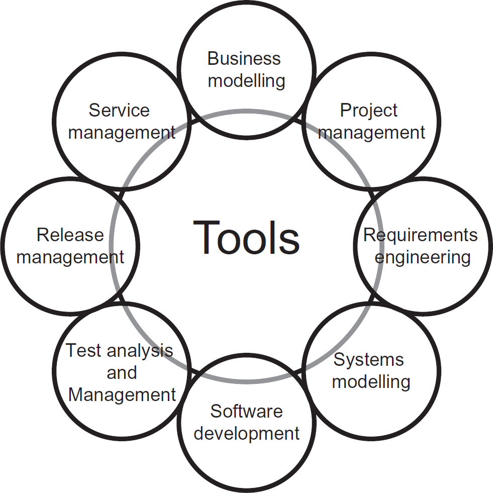
Some tools specialise in specific aspects or phases of a solution’s lifecycle, from business modelling tools through computer-aided software engineering, (CASE) tools linking through to IT service and support management (ITSSM) tools. Figure 14.1 shows the areas covered by tools.
Figure 14.1 Areas covered by solution development tools
Business modelling and architecture
Tools that support this area allow the business to develop, implement and maintain business models and architectures of an organisation’s:
- context and links with the outside world;
- business functions and processes;
- products and services;
- internal structure and roles;
- information systems (IS) including information technology (IT).
In this context, the IS/IT are simply components that provide services to the business and perhaps direct to customers. As the organisation seeks to change its model in any respect, then that often requires a change in the IS/IT and the drivers for such a change are apparent as are the dependencies across the business architecture that need to be handled.
Project management tools
Often, business changes – especially significant changes to the IS/IT – require formal project management. Although many project management tools tend to focus on planning, resource management and progress reporting, at the heart of any project is a definition of what that project is delivering as outputs and the benefits expected by the business as eventual outcomes. These are often encapsulated in the business case and/or project initiation document as the high-level project and business objectives. These may be derived from the business modelling described above and form the basis for further requirements engineering.
Requirements engineering tools
Computer-aided requirements engineering (CARE) tools are specialised tools; they sometimes operate as a stand-alone tool or as a function of a broader business modelling or CASE tool.
Requirements may be documented using pen and paper or by using generic word-processing and spreadsheet tools. There are, however, aspects of requirements engineering which specialised tools can make a lot easier, including:
- version control;
- team support and access security;
- change control;
- configuration management;
- traceability.
System modelling tools
A fundamental element of many CASE tools is the ability to support model-driven engineering. That is, to move from abstract models of a system through to an implemented version of that model and vice versa. In Chapter 7 (‘Systems modelling techniques’), the U-curve describes how:
- the current, ‘as is’ physical system can be documented (potentially through an automated tool process called reverse engineering)
- this can be abstracted to a logical ‘as is’ model. Business requirements and changes can then be applied leading to...
- the logical ‘to be’ model, which can then be designed into a...
- physical ‘to be’ design that can be implemented.
Chapter 7 also discusses how several different views (for example functional, data and event) can be used in combination to provide a more complete understanding of the system.
System modelling tools can often be used by a number of roles, from business analysts through system analysts and designers to developers, each evolving the models towards the solution. Testers can also take these models as a basis to analyse and design the testing; or in some cases, these tools integrate with the testing tools they employ.
Software development tools
Fundamentally, development tools provide the ability for developers to take a design, and either write source code or use a visual notation that links components into an assembly for which source code is automatically generated.
Source code then needs to be able to be executed by the computer. There are various forms for this:
- Interpreted code. The source code is interpreted as a set of instructions at run-time. This includes older implementations of BASIC, COBOL and other procedural languages. More relevant in the twenty-first century, it also includes scripting languages such as JavaScript, which is interpreted server or client-side – for example, Javascript embedded in a web page and interpreted by a browser.
- Compiled (and linked) native executable code. The source code is taken through what is typically a two-stage process. It is first compiled into an intermediate link-code which is then linked to similar code in statically-linked libraries to produce a version of the code that is more directly executable by a specific platform.
- Partially compiled code. An example of this would be Java, which is compiled into a ‘byte code’ that can be executed by a Java run-time environment (which often performs the final linking just-in-time).
Modern development tools typically allow the developer to create and run these in real time, enabling a very incremental means of developing software, while performing some run-time tests.
Various features expected of development tools include:
- Syntax support: indicating an invalid syntax as it is typed.
- Checking references: although the syntax may be correct, the libraries, functions, variables may be incorrect. Tools can either highlight these before compile/link cycles and even provide valid choices as the developer types.
- Integration with team repository and version control tools: providing the ability to baseline software and undo changes.
- Model to source code support: converting design models into skeleton source code with features and dependencies carried over.
In many cases, the code development and system modelling functions are incorporated into a single tool.
Testing tools
Whereas some unit testing features are often incorporated into development tools, the testing discipline typically employs specialist tools, often referred to as computer-aided software testing (CAST) tools. These do more than simply run automated tests on the software, and other features include:
- Test management – allows test managers to plan, review, evaluate and report on a testing programme.
- Test design – allows testers to analyse requirements and design in order to design an appropriate level of testing. This includes the design of test scenarios, sample data and boundary tests.
- Automated testing – allows the execution of automated, repeatable tests.
- Test analysis – allows testers to review the results of tests and to determine what feedback to provide to the developers about defects and what changes to make to the test designs to increase the effectiveness of the tests.
Elements of testing, such as evidence of testing, may be linked to earlier elements including traces back to the requirements that have been delivered.
Release management
Release management occurs at the handover from development to operations. Many modern enterprise IS/IT solutions have a number of significant issues to manage at release, including the dependencies between different hardware and software components in a distributed architecture, the release and configuration of which has to be coordinated in order to avoid disruption to day-to-day business activities. These include:
- server hardware and software components;
- client-side hardware and software components;
- infrastructure components, such as networks and various middleware;
- a prepared user base, including provision of training and documentation;
- a prepared operations team, including support and management tools and processes (including help-desk services).
Through design, development and testing activities, specific combinations of configurations should have been planned and tested for release. This release could be through pilots, an incremental release or a ‘big-bang’ delivery. These tools may deploy updates out to clients either as a pull (clients specifically requesting updates) or push (updates deployed remotely) to a plan.
Service management tools
Commonly referred to as IT Service and Support Management (ITSSM) tools. Once released, the solutions still require:
- monitoring against service levels;
- support through help-desk services;
- implementation of business-as-usual maintenance;
- documentation of what is deployed.
Configuration management is a major contributor of effective service management. The configuration management database (CMDB) is a key feature of any ITSSM tool.
One of the outputs from service management may be a set of change requests and other pressures for change that initiate a new solution development cycle.
CONCLUSION
What’s in a name?
Throughout this chapter, there has been reference to a range of disciplines, activities and abbreviations.
For solution development tool support, the broadest term is CASE (computer-aided software engineering), which typically covers requirements through to testing. Within that space, we find specialist tools such as CARE (computer-aided requirements engineering) and CAST (computer-aided software testing) as well as the core software development tools that manage code and produce deliverable software components.
At either ‘end’ of this continuum, we have business tools and service management tools that are primarily focused on the business operating model; modelling, monitoring and looking for issues that drive change for business improvement.
Evaluating tools
Precisely where one definition ends and another begins is often down to the tool supplier, who will often adopt a broad term for marketing reasons. Organisations or individuals need to assess and give careful consideration as to which tools are adopted, taking into consideration a number of factors:
- Requirements: precisely what does the organisation expect the tool to do? Produce requirements as one should for any COTS (commercial off-the-shelf) business application.
- Functionality: beware lists of ‘features’ in marketing collateral. Precisely what can various roles do with the tool and do these meet the organisation’s requirements?
- Suitability: does the tool fit with the organisation’s standards, processes and notations or will the organisation need to change to fit with the tool?
- Compatibility: the disciplines that utilise tools, as described above, may exist within their own silos, but tools will be more effective if they aid communication across the disciplines through tools being able to share information and interact effectively. Tools also need to be compatible with any existing operational applications and infrastructure if they are to monitor, reverse-engineer and maintain them. If part of the development is outsourced or offshored, the ability to communicate and interact effectively through tools’ exchanging information may be of immense benefit.
- Technical: what are the technical requirements for the tools and is this compatible with existing hardware?
- Skills: what specific skills are required to use the tool? Do the tool users require tool specific or other training in order to be effective?
- Costs: including up-front and ongoing licensing costs, as well as costs of support and training to use the tool.
Ultimately, the choice should be determined through a business case as selecting and implementing the wrong tool can seriously damage an organisation’s capability to develop solutions.
Benefits and pitfalls of adopting tools
The development and operation of solutions that incorporate IS/IT elements are logically possible without the support of automated tools. However, the complexity and scale of such solutions often makes this unfeasible.
There is a massive marketplace where tools of all types, shapes and sizes are available. Different disciplines may choose their own tools, but even more benefit can be achieved where these tools integrate or share in order to provide a better quality of support.
The tools themselves are, however, only as useful as those who use them; users need to have the necessary skills and knowledge. If, for example, a systems analyst doesn’t understand the syntax and appropriate use of a particular modelling language such as UML, then giving them a tool based on that language will not help. Indeed it risks the opposite.
There is also the danger of a misplaced perception and confidence that anything output by a tool must be ‘OK’ or correct. There’s an abbreviation, GIGO, from the early days of computing, that rings true even more today with the widespread use of tools: Garbage In = Garbage Out!
FURTHER READING
Avison, D. and Fitzgerald, G. (2002) Information systems development: methodologies, techniques and tools. McGraw Hill, Maidenhead.
Black, R. (2009) Managing the testing process: practical tools and techniques for managing hardware and software testing (3rd edition). John Wiley and Sons, Indianapolis, IN.
Reifer, D. J. (2012) Software change management: case studies and practical advice. Microsoft Press, Washington, DC.