For about seven years my family and I lived in the California Sierras. During that time I developed a passion for rustic mountain living as well as most environmental associations related to the mountains and the Old West: snow, historic mining towns, coaches and wagons, treasure hunting, narrow gauge railroads, wildland fire fighting, and other miscellaneous rural benefits. Now that I have milled that Old West imagery into your mind "ore" bored you to death, you can continue reading what I fondly refer to as the mangling of bits. This is one of my favorite sections, because with their use, I typically devise speedier methods for use in the manipulation of data. I label this "thinking out of the box," sometimes referred to as "Thar's gold in them thar bits!"
Bit mangling relates to the individual twiddling of bits using Boolean logic such as NOT, AND, OR, XOR, or some combination thereof. Each bit is individually isolated so no bit affects any adjacent bit encapsulated by the register. In vector mathematical operations, groups of bits are isolated so that an operation on one vector group does not affect another. Boolean operations are similar but on an individual bit basis. Each group in this case is a group of one bit; thus, an operation to a single bit does not affect an adjacent bit. This is why there are no vector type Boolean operations. There are operations that do, however, use 32/64-bit general-purpose registers, 64-bit MMX registers, and 128-bit SSE2 registers for Boolean operations so as to manipulate more bits simultaneously in parallel.
These are heavily used by algorithms utilizing vectors, which is why they are in this book. Included in this chapter are the electronic symbols for each logical operation. Typically, I use my own books for reference, and from time to time I have found that drawing logic circuits using digital logic symbols actually makes more complex Boolean logic algorithms easier for me to simplify. Maybe it will work the same for you.
Any processor professing to contain a multimedia, SIMD, packed, parallel, or vector instruction set will contain almost all of the following instructions in one form or another. Parallel instructions typically do not have a Carry flag as found in some of the older scalar based instruction sets using general-purpose registers, such as the 80×86. They tend to lose overflows through the shifting out of bits, wraparound of data, or saturation. Another item to note is that not all the displayed diagrams are used by all the various 80×86 processors defined. Over the years the functionality has been enhanced, so older processors will not have the same abilities as the newer processors.
It must be reiterated that you watch the alignment of your data objects in memory very closely. It takes extra overhead to adjust the memory into an aligned state and it is a lot more efficient to ensure that they are aligned in the first place. Your code will be smaller and faster! This will be made obvious by the sample code included in this chapter.
You will find in this chapter and throughout this book sections titled "Pseudo Vec." As processors are enhanced, new superset functionality is given to them such as SIMD operations. Some of you, however, are still programming for older processors and need the newer functionality, while some of you require a more in-depth understanding of vector operations. The "Pseudo Vec" sections are for you!
Workbench Files: Benchx86chap04projectplatform
and | rmDst(8/16/32/64), #(8/16/32) | [Un]signed | ||
and | rmDst, rSrc(8/16/32/64) | |||
and | rDst, rmSrc(8/16/32/64) | |||
MMX | pand | mmxDst, mmxSrc/m64 | [Un]signed | 64 |
SSE | xmmDst, xmmSrc/m128 | Single-precision | 128 | |
SSE2 | pand | xmmDst, xmmSrc/m128 | [Un]signed | 128 |
" | andpd | xmmDst, xmmSrc/m128 | Double-precision | 128 |
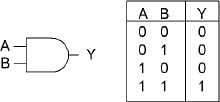
An AND operation means that one would need both A and B to be true to have a true result. The AND general-purpose instruction logically AND's the 8-, 16-, 32-, or 64-bit source with the destination and stores the result in the destination. An 8-bit source value can be sign extended to a 16-, 32-, or 64-bit value. A 32-bit source value can be sign extended to a 64-bit destination. The source can be an immediate value, a register, or memory. The destination is a register or memory. A memory-to-memory operation is invalid!
Flags: With the AND general-purpose instruction, the Carry and Overflow flags are cleared. The Zero flag is set if all destination bits are 0, thus destination = 0. The Sign flag reflects the state of the MSB. | ||||||
|---|---|---|---|---|---|---|
Flags | O.flow | Sign | Zero | Aux | Parity | Carry |
0 | × | × | - | × | 0 | |
The following 32-bit example demonstrates this:

This is typically used for masking operations as in jump vectors:
        and     ebx,0000111b    ; Mask for 0...7 =8 vectors
        jmp     VecTbl[ebx*4]   ; Jump using the vector
The multimedia extension instruction is a parallel operation that uses a Boolean AND operation upon each of the corresponding 64 or 128 bits.
The source A and B are aSrc (xmmSrc) and bSrc (xmmDst), and the result is stored in the destination Dst (xmmDst). The instruction may be labeled as packed, parallel, or vector but each bit is in reality isolated from each other so there is no need for a data bit block arrangement. No flags are set.
msk     dd      00000ffffffff0000h
dat     dd      00000a5a50000ff11h


        mov     esi,offset dat   ; Data pointer
        mov     ebx,offset msk   ; Mask pointer

        movq    mm7,[esi]        ; Get 64 bits of data
        pand    mm7,[ebx]        ; AND it with the mask data
        movq    [edi],mm7        ; Save the masked data
For the SSE instruction, the ANDPS is a bitwise AND of four packed single-precision floating-point values with a bit mask.
For the SSE2 instruction, the ANDPD is a bitwise AND of two packed double-precision floating-point values with a bit mask.
These floating-point related instructions will be discussed in Chapter 8, "Floating-Point Anyone?"
The following C code demonstrates the simulated vector functionality of a logical AND upon a 128-bit vector. The code sample logical AND's the four packed 32-bit values from vector A and B, to effectively AND all 128 bits and then stores the result in vector D. Note that the function stores the result pointed to by the first function argument.
Example 4-1. ...chap04pboolPBool.cpp
  void vmp_pand(void *pvD, void *pvA, void *pvB)
  {

    uint32 *pD, *pA, *pB;

    ASSERT_PTR16(pvD);
    ASSERT_PTR16(pvA);
    ASSERT_PTR16(pvB);

    pD=(uint32*) pvD;
    pA=(uint32*) pvA;
    pB=(uint32*) pvB;
    *(pD+0) = *(pA+0) & *(pB+0);
    *(pD+1) = *(pA+1) & *(pB+1);
*(pD+2) = *(pA+2) & *(pB+2);
*(pD+3) = *(pA+3) & *(pB+3);
}The assertion macro ASSERT_PTR4 could have been used instead since memory alignment for generic code only needs to be aligned to four bytes to support a 32-bit value, but the ASSERT_PTR16 was used instead to ensure 16-byte vector data alignment
This first code snippet has been constructed to take advantage of instruction pipelining and uses a general-purpose 80×86 assembly language logical AND. Please note the code indicated in bold. By substituting alternative mnemonics, such as the Boolean logic instructions ANDC, OR, and XOR that have not been discussed yet, in place of AND, the code encapsulation (code snippets) can be mostly reused.
Example 4-2. ...chap04pboolPBoolx86M.asm
  mov    eax,pvA     ; A (Source) Vector
  mov    ebx,pvB     ; B (Source) Vector
  mov    edx,pvD     ; D (Destination) Vector
The previous MOV instructions are common to the following code samples and thus not replicated in those samples, but they need to be recognized as loading general-purpose registers in preparation for those samples.
mov ebp,[eax+0] ; Read A lower 64 bits mov esi,[eax+4] mov ecx,[ebx+0] ; " B " " mov edi,[ebx+4]and ebp,ecx;ANDbits (31...0)and esi,edi;ANDbits (63...32) mov [edx+0],ebp ; Write lower 64 bits mov [edx+4],esi mov ebp,[eax+8] ; Read A upper 64 bits mov esi,[eax+12] mov ecx,[ebx+8] ; " B " " mov edi,[ebx+12]and ebp,ecx;ANDbits (95...64)and esi,edi;ANDbits (127...96) mov [edx+8],ebp ; Write upper 64 bits mov [edx+12],esi
An optimization worth noting is the interlacing of the general-purpose registers into pairs to minimize dependencies.
If in 64-bit mode, you can directly AND 64 bits of memory without using MMX registers.
Example 4-3. ...chap04pboolPBoolx86M.asm
mov rax,pvA ; A (Source) Vector mov rbx,pvB ; B (Source) Vector mov rdx,pvD ; D (Destination) Vector mov r8,[rax+0] ; Read A lower 64 bits mov r9,[rax+8] ; Read A upper 64 bits mov r10,[rbx+0] ; Read B lower 64 bitsmov r11,[rbx+8]; Read Bupper64 bitsand r8,r10;ANDbits (63...0)and r9,r11;ANDbits (127...64) mov [rdx+0],r8 ; Write lower 64 bits mov [rdx+8],r9 ; Write upper 64 bits
In the following examples the burden is placed upon 64- or 128-bit registers, so the 32-bit general-purpose registers are only used for memory access. With the MMX instructions, only 64 bits can be manipulated at a time so the data is handled as upper and lower 64-bit pairs. It also helps minimize processor stalls due to register dependencies.
Example 4-4. ...chap04pboolPBoolx86M.asm
movq mm0,[ebx+0] ; Read B lower 64 bits movq mm1,[ebx+8] ; " B upper " movq mm2,[eax+0] ; Read A lower 64 bits movq mm3,[eax+8] ; " A upper "pand mm0,mm2;ANDlower 64 bitspand mm1,mm3;ANDupper 64 bits movq [edx+0],mm0 ; Write D lower 64 bits movq [edx+8],mm1 ; " upper "
For full 128-bit handling on an 80×86 processor it becomes necessary to require a minimum of a Pentium 4 with the SSE2 instruction set. The following SSE2 example is a better solution as compared to the MMX version. Despite the register dependency stall that is in this specific example, there is no FPU/MMX conflict; thus there is an avoidance of the MMX registers, all 128 bits are handled simultaneously, and the code size is smaller. There is a little problem of memory alignment with SSE and SSE2, so two versions of the function will be needed if strict memory alignment procedures are not followed.
Example 4-5. ...chap04pboolPBoolx86M.asm
movdqaxmm0,[ebx] ; Read B Aligned 128 bitsmovdqaxmm1,[eax] ; Read Apandxmm0,xmm1 ; AND 128 bitsmovdqa[edx],xmm0 ; Write D Aligned 128 bits
Note the use of MOVDQA (aligned) used previously and MOVDQU (unaligned) used in the following examples. The code is virtually identical for both examples, except that if the data is misaligned and if the MOVDQA instruction is utilized, an exception will occur. If memory alignment cannot be guaranteed, the following (slightly slower version) should be used instead.
Example 4-6. ...chap04pboolPBoolx86M.asm
movdquxmm0,[ebx] ; Read B non-aligned 128 bitsmovdquxmm1,[eax] ; Read Apandxmm0,xmm1 ; AND 128 bitsmovdqu[edx],xmm0 ; Write D non-aligned 128 bits
I was not trying to pull the wool over your eyes or anything. The really nice feature for the SSE and SSE2 instructions is that for both aligned and unaligned data, the code is virtually identical except for the method of access. The only trick is to make sure it is properly aligned before using MOVDQA. If in doubt, use the instruction MOVDQU; otherwise an exception will occur upon that misaligned access.
You may now be thinking, but why bother using MOVDA? Why not just use MOVDQU all the time?
The answer? Your code will run slower, and that is contrary to the reason for writing your code in assembly or using vector instructions!
or | rmDst(8/16/32/64), #(8/16/32) | [Un]signed | ||
or | rmDst, rSrc(8/16/32/64) | |||
or | rDst, rmSrc(8/16/32/64) | |||
MMX | por | mmxDst, mmxSrc/m64 | [Un]signed | 64 |
SSE | orps | xmmDst, xmmSrc/m128 | Single-precision FP | 128 |
SSE2 | por | xmmDst, xmmSrc/m128 | [Un]signed | 128 |
" | orpd | xmmDst, xmmSrc/m128 | Double-precision FP | 128 |
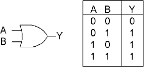
An OR operation means that one would need either A or B to be true to have a true result. The OR general-purpose instruction logically OR's the 8-, 16-, 32-, or 64-bit source with the destination and stores the result in the destination. An 8-bit source value can be sign extended to 16-, 32-, or 64-bit value. A 32-bit source value can be sign extended to a 64-bit destination.
The source can be an immediate value, register, or memory. The destination is a register or memory. A memory-to-memory operation is invalid!
Flags: With the OR general-purpose instruction, the Carry and Overflow flags are cleared. The Zero flag is set if all destination bits are 0, thus destination = 0. The Sign flag reflects the state of the MSB. | ||||||
|---|---|---|---|---|---|---|
Flags | O.flow | Sign | Zero | Aux | Parity | Carry |
0 | × | × | - | × | 0 | |
The following 32-bit example demonstrates this:
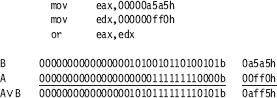
This multimedia extension instruction is a parallel operation that uses a Boolean OR operation upon each of the corresponding 64 or 128 bits. The source A and B are aSrc (xmmSrc) OR bSrc (xmmDst), and the result is stored in the destination Dst (xmmDst). The instruction may be labeled as packed, parallel, or vector, but each bit is in reality isolated from each other so there is no need for a data bit block arrangement. The following 32-bit example demonstrates that.
For the SSE instruction, the ORPS is a bitwise OR of four packed single-precision floating-point values with a bit mask.
For the SSE2 instruction, the ORPD is a bitwise OR of two packed double-precision floating-point values with a bit mask.
These floating-point related instructions will be discussed in Chapter 8, "Floating-Point Anyone?"
The following C code demonstrates the functionality of a logical OR upon a 128-bit vector. The code sample logical OR's the four blocks of 32-bit values from vector A and B 32 bits at a time four times to effectively OR all 128 bits, and then stores the result in vector D. Note that the function stores the result pointed to by the first function argument.
Example 4-7. ...chap04pboolPBool.cpp
  void vmp_por(void *pvD, void *pvA, void *pvB)
  {
    uint32 *pD, *pA, *pB;

    pD=(uint32*) pvD;
    pA=(uint32*) pvA;
    pB=(uint32*) pvB;
    *(pD+0) = *(pA+0) | *(pB+0);   // {31...0}
    *(pD+1) = *(pA+1) | *(pB+1);   // {63...32}
    *(pD+2) = *(pA+2) | *(pB+2);   // {95...64}
    *(pD+3) = *(pA+3) | *(pB+3);   // {127...96}
  }
See the code snippets from the previously discussed instruction AND, then substitute the instruction {|, or, por} for the {&, and, pand} accordingly.

xor | rmDst(8/16/32/64), #(8/16/32) | [Un]signed | ||
xor | rmDst, rSrc(8/16/32/64) | |||
xor | rDst, rmSrc(8/16/32/64) | |||
MMX | pxor | mmxDst, mmxSrc/m64 | [Un]signed | 64 |
SSE | xorps | xmmDst, xmmSrc/m128 | Single-precision FP | 128 |
SSE2 | pxor | xmmDst, xmmSrc/m128 | [Un]signed | 128 |
" | xorpd | xmmDst, xmmSrc/m128 | Double-precision FP | 128 |
An XOR operation means that one would need either A or B to be true but not both to have a true result. The XOR general-purpose instruction logically AND's the 8-, 16-, 32-, or 64-bit source with the destination and stores the result in the destination. An 8-bit source value can be sign extended to a 16-, 32-, or 64-bit value. A 32-bit source value can be sign extended to a 64-bit destination. The source can be an immediate value, a register, or memory. The destination is a register or memory. A memory-to-memory operation is invalid.
Flags: With the XOR general-purpose instruction, the Carry and Overflow flags are cleared. The Zero flag is set if all destination bits are 0, thus destination = 0. The Sign flag reflects the state of the MSB. | ||||||
|---|---|---|---|---|---|---|
Flags | O.flow | Sign | Zero | Aux | Parity | Carry |
0 | × | × | - | × | 0 | |
The best method to clear a register is to exclusive or (XOR) it with itself. The newer processors have incorporated optimization logic that encodes that since there are no dependencies upon a read operation when the source and the destination are the same (as the end result is cleared bits), and so merely writes all bits with zero.
The following 32-bit example demonstrates this:

This is typically used for the flipping of selected bits.
This multimedia extension instruction is a parallel operation that uses a Boolean XOR operation upon each of the corresponding 64 or 128 bits. The source A and B are aSrc (xmmSrc) XOR bSrc (xmmDst), and the result is stored in the destination Dst (xmmDst). The instruction may be labeled as packed, parallel, or vector, but each bit is in reality isolated from each other so there is no need for a data bit block arrangement.
For the SSE instruction, XORPS is a bitwise XOR of four packed single-precision floating-point values with a bit mask.
For the SSE2 instruction, XORPD is a bitwise XOR of two packed double-precision floating-point values with a bit mask.
These floating-point related instructions will be discussed in Chapter 8, "Floating-Point Anyone?"
The following C code demonstrates the functionality of a logical XOR upon a 128-bit vector. The code sample logical XOR's the four blocks of 32-bit elements from vector A and B to effectively XOR all 128 bits and then stores the result in vector D. Note that the function stores the result referenced by the first function parameter pointer.
Example 4-8. ...chap04pboolPBool.cpp
  void vmp_pxor(void *pvD, void *pvA, void *pvB)
  {
    uint32 *pD, *pA, *pB;

    pD=(uint32*) pvD;
    pA=(uint32*) pvA;
    pB=(uint32*) pvB;
    *(pD+0) = *(pA+0) ^ *(pB+0);    // {31...0}
    *(pD+1) = *(pA+1) ^ *(pB+1);    // {63...32}
    *(pD+2) = *(pA+2) ^ *(pB+2);    // {95...64}
    *(pD+3) = *(pA+3) ^ *(pB+3);    // {127...96}
  }
See the code snippets from the previously discussed instruction AND, then substitute the instruction {^, xor, pxor} for the {&, and, pand} accordingly.
Another use for this operation is as a Boolean NOT (one's complement) operator. By using an input A and setting B permanently to a logical one, an inverse bit is achieved. Note the following table where zero becomes one and one becomes zero.

Figure 4-1. Example of using a logical XOR with a logical true bit to achieve the equivalent of a logical NOT condition.
As can be seen, input A and output Y are the exact opposite. Keep in mind that Boolean logic is bit based and bit isolated so that adjacent bits do not affect each other.

Mnemonic | P | PII | K6 | 3D! | 3Mx+ | SSE | SSE2 | A64 | SSE3 | E64T |
|---|---|---|---|---|---|---|---|---|---|---|
NOT |
|
|
|
|
|
|
|
|
|
|
This instruction logically inverts the bits of the destination. All ones become zeros, and all zeros become ones.
Flags: None are affected by this opcode. | ||||||
|---|---|---|---|---|---|---|
Flags | O.flow | Sign | Zero | Aux | Parity | Carry |
- | - | - | - | - | - | |

And guess what you get when you flip it again?
The original value! Flip-flop.
neg | rmDst(8/16/32/64) | [Un]signed |
This instruction logically inverts the sign of the number.
Flags: Carry is cleared if the destination is 0; else it is set. The other bits are set accordingly from its results. | ||||||
|---|---|---|---|---|---|---|
Flags | O.flow | Sign | Zero | Aux | Parity | Carry |
× | × | × | × | × | × | |


Another use for an XOR is in an implementation for a negation (two's complement). As a refresher, a subtraction is a two's complement followed by an addition. By inverting all bits, a one's complement is achieved. The next step for the two's complement is by an increment (addition of one) of this value. This is followed by the addition, which effectively results in the subtraction.
This operation is the result of a Boolean NOT (one's complement) operator that was just discussed, followed by an increment or an addition by one. Of course, this is not as slick as a reverse subtraction where...
-A = A ISUB 0 thus -A = 0 - A
but not all processors support that. Keep in mind though, that when dealing with pipelining your code, a two-step operation may be more helpful than a single step.
An interesting use for a logical XOR is as a butterfly switch to allow for branchless coding. Branchless code is discussed in Chapter 11, but this is a good time to take a break and twiddle some bits. Normal coding that uses branching is typically taught using something as follows:
  #define FLIP  -30
  #define FLOP   47

    if (FLIP == nf)
    {
      nf = FLOP;
    }
    else
    {
      nf = FLIP;
    }

...or...

   nf = (FLIP == nf) ? FLOP : FLIP;
No matter which way you coded it, it is the same, identical code. This is fine and dandy, but the branching and especially a possible misprediction of a branch takes time and there are two branches to contend with. If in a flip, it flops, and if in a flop, it flips. Of course, instead of two branches such as the previous code snippet, it could always be coded for one branch such as follows:
nf = FLIP;
if (FLIP == nf)
{
  nf = FLOP;
}
The code, if not a FLIP as in the previous code snippet, branches around and continues on, but again, there could be a misprediction.
A misprediction is as it sounds. A more advanced CPU will predict that at an if-then conditional, it will take the branch and do the conditional or branch around, thus the if-then-else. The problem is that the CPU gains efficiency by predicting that it is correct because it is preloading memory and, in some cases, executing instructions that are further down in the code. The punishment comes that if it predicted wrong, that memory has to be thrown away and the results of the calculations it processed ahead of time disposed of. Then it needs to continue processing down the correct path. Either way, this is very time consuming, and so alternative (branchless) methods need to be devised if possible.
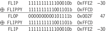
My favorite solution is a branchless result so there is no misprediction and the appropriate value can be selected with a butterfly switch. Let's examine these two values more closely:
FLOP    =       47      =       0x002F    =   0000000000101111b
FLIP    =      -30      =       0xFFE2    =   1111111111100010b
...and calculate the logical XOR of those two values:
FLIPPY = -51 = 0xFFCD = 1111111111001101b
So if in our code initialization we preset a value:
nf = FLOP;
...and in place of the branching code the following snippet is used instead:
xor nf,nf,FLIPPY // FLIP/FLOP
...then each time the code is executed it will flip to the alternate value.
FLIP FLOP FLIP FLOP FLIP FLOP FLIP, etc.
Pretty cool, huh! And the best part is the actual code is a single instruction, not a group of instructions to process a branch and decide whether to branch or not! The code runs a lot faster, and it's smaller. This also works with non-definitions as well. Initialize with the following:
nf = valueA;            // First value
iFlipVal = nf ^ valueB; // Butterfly key
...and then select the value with the following:
nf = nf ^ iFlipVal;
... and it works great in a parallel configuration. Different butterflies to control different elements, all in parallel.
If anything, at least this book is informative!
![]() I know this is not x86 related, but what instruction is thought to be missing from the VU coprocessor on the PS2?
I know this is not x86 related, but what instruction is thought to be missing from the VU coprocessor on the PS2?
This seems to be a popular interview question, as I have encountered it numerous times. Yes, I know, I digress. The 80×86 supports the XOR instruction as was discussed, but this is good practice for the other Boolean instructions that have been touched on in this chapter.
After interviewers ask this question, they then sometimes want to know how to write equivalent code. Funny thing is that they do not seem to remember the answer themselves. I will hastily draw out the following truth table from left to right, and then draw the circuit for good measure. (That is, if I am not too tired and frustrated from having to answer programming questions all day long!)
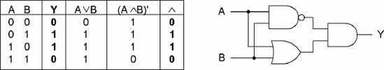
Figure 4-2. A four-gate (OR, NOT-AND, AND) solution to achieve an equivalent result of a logical XOR
I will then hesitate for a second and then announce, "But wait!" This takes four logical operations — an OR, AND, NOT, then AND. So instead let's make this a bit smaller. If ANDC type functionality is used (which has not been discussed yet)...

...notice the swapped inputs and the gate functionality similar to a logical AND, then the outputs are logical OR gated together. So now it is down to two!
But wait. What if there were no NOT, NOR, XOR, or ANDC instruction? At this point, if you replicate what is being presented here at your interview as a response to the question, you will either come off sounding like a really smart guy or a prima donna, depending on how you do it. So you then announce, "But wait! There is no NOT or ANDC, so how do we do it!" (Keep in mind there is a NOT and an ANDC on the 80×86.) "Ever hear of a half-adder?" It has the same result as that of an XOR except that it also contains a carry, and that is where the problem resides. That carry bit is contaminating an adjacent bit.
Table 4-1. A half-adder solution. By ignoring the carry, a logical XOR will result.
A + B | Carry | Y | |
|---|---|---|---|
0 | 0 | 0 | 0 |
0 | 1 | 0 | 1 |
1 | 0 | 0 | 1 |
1 | 1 | 1 | 0 |
So if the bits are stripped into an odd-even arrangement, the A and B (odd bits) are summed, then masked with the 1010 bit mask pattern. The A and B (even bits) are summed, then masked with the 0101 even bit mask pattern. The results of the odd and even are logical OR'd with each other; effectively a logical XOR is simulated. Let's examine some 16-bit data:

So effectively all the odd bits are separated from the even bits. Odd bits are stored in a {o0o0...o0o0} bit pattern while the even bits are stored in a {0e0e...0e0e} bit pattern. So by a logical AND with the odd {10} and even {01} binary masks, an un-interlaced form is generated. This allows the odd and even bits to be handled separately, and the overflow from any operation is stored in the adjacent (next higher) bit. This means any carry will be ignored when the odd and even results are blended back together. The carry results will be removed using the same odd or even mask. Notice the bits indicated in bold are the usable result from the AND.
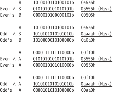
Now the even and odd values of A and B are summed up separately. Note that we only care about the resulting bits in bold and not the others, as those are the individual carries, which are stripped by the logical AND of the original mask.

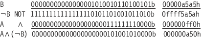
Now logical OR the even bits and odd bits back together for the interlaced XOR result.

And when compared to the expected results of a "real" XOR:
AB 1010101001010101b 0aa55h
...exactly the same. Okay, okay, a lot more operations, but just another technique for your repertoire. But now that you have special insight into the problem, here is the start of solving this equation for yourself!
You did not think that I would be giving you all the answers, did you?

MMX | pandn | mmxDst, mmxSrc/m64 | [Un]signed | 64 |
SSE | andnps | xmmDst, xmmSrc/m128 | Single-precision FP | 128 |
SSE2 | pandn | xmmDst, xmmSrc/m128 | [Un]signed | 128 |
" | andnpd | xmmDst, xmmSrc/m128 | Double-precision FP | 128 |
This instruction is a one's complement of B logical AND with A.
Dst=Src(¬Dst′)
This multimedia extension instruction is a parallel operation that uses a Boolean NOT AND operation upon each of the corresponding 64 or 128 bits. The source A and B are aSrc (xmmSrc) and a one's complement of bSrc (xmmDst), and the result is stored in the destination Dst (xmmDst). The instruction may be labeled as packed, parallel, or vector, but each bit is in reality isolated from each other so there is no need for a data bit block arrangement. The following 32-bit example demonstrates this.
For the SSE instruction, ANDNPS is a bitwise NOT AND of four packed single-precision floating-point values with a bit mask.
For the SSE2 instruction, ANDNPD is a bitwise NOT AND of two packed double-precision floating-point values with a bit mask.
These floating-point related instructions will be discussed in Chapter 8, "Floating-Point Anyone?"
The following C code demonstrates the functionality of a logical ANDC upon a 128-bit vector. The code sample logical NOT's the bits from vector B, then AND's these bits with vector A, 32 bits at a time, four times, to effectively ANDC all 128 bits, and then stores the result in vector D. Note that the function stores the result referenced by the first function parameter pointer.
Example 4-9. ...chap04pboolPBool.cpp
  void vmp_pandc(void *pvD, void *pvA, void *pvB)
  {
    uint32 *pD, *pA, *pB;

    pD=(uint32*) pvD;
    pA=(uint32*) pvA;
    pB=(uint32*) pvB;

    *(pD+0) = (0xffffffff ^ *(pB+0)) & *(pA+0);
    *(pD+1) = (0xffffffff ^ *(pB+1)) & *(pA+1);
    *(pD+2) = (0xffffffff ^ *(pB+2)) & *(pA+2);
    *(pD+3) = (0xffffffff ^ *(pB+3)) & *(pA+3);
  }
See the code snippets from the instruction AND, then substitute the instruction {pandn} for the {pand} accordingly.
Make a NOT gate using
an XOR gate
NAND gate
NOR gate.
Write a software algorithm for the following equation.
D=(-1-(A
B))(AB)What does the equation do?
Draw an XOR circuit using only OR gates and AND gates, and a subtraction.
Make a 128-bit XOR using only bitwise OR and bitwise AND, and a subtraction.
Write code to change the value of tri-state data. Note the series of states is a repeating pattern {0, 1, 2, 0, 1, 2, ...}. The starting state is State #0.
State | 0 | 1 | 2 | 0... |
Value | 0×34 | 0×8A | 0×E5 | 0×34 |
Extra credit:
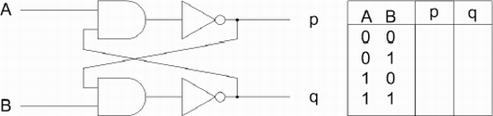
This cross-coupled SR flip-flop will be more familiar to those of you with electronics experience. Using A=0 and B=0 as the starting state, finish the logic table.
How does this circuit function? What are the behaviors of p and q if the data inputs of A and B are changed to a new state? Try all 12 possibilities. How would you code it?