Think of this chapter as a continuation of the previous chapter, "Bit Mangling."
This chapter deals with bit wrangling and thus the movement of bits. They can be shifted into oblivion, rotated, and watched going around and around. As Bugs Bunny would say, "Dizzing, ain't it!"
Bit wrangling actually occurs with the rotation and logical and arithmetic shifting of bits within each parallel bit range of packed bits. Just as in the scalar point of view of a similar general-purpose CPU instruction, the bits can be used for masking, base two multiplication and division, and other functionality.
It must be reiterated that you watch the alignment of your data objects in memory very closely. It takes extra overhead to adjust the memory into an aligned state, and it is a lot more efficient to ensure that they are aligned in the first place. Your code will be smaller and faster! This will be made obvious by the sample code included in this chapter.
Workbench Files:Benchx86chap05projectplatform
project | platform | |
|---|---|---|
Shift/Rotations | prot | vc6 |
vc.net |
It is recommended that you use an addition instead of a shift on newer processors for optimization.
      A + A  = 2A = A << 1
2A + 2A = 4A = A << 2shl | rmDst(8/16/32/64), 1 | [Un]signed |
shl | rmDst(8/16/32/64), #(2n-1) | |
shl | rmDst(8/16/32/64), cl |
This instruction is a multiplier (2n) by shifting the destination to the left and shifting the most significant bit (MSB) into the carry. The previous content of the carry is shifted out and lost, and a 0 is shifted into the least significant bit (LSB). The count indicating the number of bits to shift is invalid if greater than or equal to width of data (2n). If shifted enough times, the data will be emptied, being set to all zeroes. If count = 0, then there is no shift and thus the destination and flags are not changed. Shift Logical Left and Shift Arithmetic Left are the same identical instruction.
Flags: Carry = last bit shifted out, Zero = 1 if all destination bits are 0, thus destination = 0. If using the shift by 1, then Overflow = 0 if Carry = MSB. | ||||||
|---|---|---|---|---|---|---|
Flags | O.flow | Sign | Zero | Aux | Parity | Carry |
× | × | × | - | × | × | |
datd dd      32
datw dw      16
datb db      8

     mov     dx,1010010110100101b  ;0a5a5h  carry=0
     mov     cl,2        ; ×4 = 22

     shl     datd,4      ; datd = 512 = 32 × 16 = 32 × (24)
     shl     dx,1        ; dx = dx × 2
     ; dx = 0100101101001010b  04b4ah  carry=1
     shl     eax,cl      ; eax = eax × 4
With Pentium processors a multiply is pretty quick, but for a 486 processor or older it was sometimes necessary and faster to do shifting and adding to compensate. For example, a video display with a resolution of 640×480x8-bit would need to calculate an actual screen (memory pointer) related to an X and Y coordinate.
    mov     ecx,X
    mov     edx,Y
    mov     edi,edx
    shl     edi,2           ; 4x
    add     edi,edx         ; 5x = (4x+x)
    shl     edi,7           ; 640x = (5x)×(128)
    add     edi,ecx         ; edi = memory index
mov es:[edi],al ; Write a byte pixelMnemonic | P | PII | K6 | 3D! | 3Mx+ | SSE | SSE2 | A64 | SSE3 | E64T |
|---|---|---|---|---|---|---|---|---|---|---|
SHLD |
|
|
|
|
|
|
|
|
|
|
shld | rmDst(16/32/64), rSrc(16/32/64), #(2n-1) | [Un]signed |
shld | rmDst(16/32/64), rSrc(16/32/64), cl |
This instruction shifts the upper half of an unsigned 64-bit integer by 2n, which shifts the source to the left into the destination to the left and shifts the most significant bit (MSB) into the carry. The previous content of the carry is shifted out and lost. (It should be noted that in reality the source is not altered, only the destination.) The count indicating the number of bits to shift is invalid if it is greater than or equal to width of data (2n). If you exceed the operand size, the result in destination is undefined. If count = 0, then there is no shift and the destination and flags are not changed.
Flags: Carry = last bit shifted out, Zero = 1 if all destination bits are 0, thus destination = 0. If using the shift by 1, then Overflow = 1 if a sign change occurred; else it is 0. | ||||||
|---|---|---|---|---|---|---|
Flags | O.flow | Sign | Zero | Aux | Parity | Carry |
× | × | × | - | × | × | |
datd    dd      32
datw    dw      16
datb    db      8

        mov     ax,0001001000110100b 01234h
        mov     dx,1010010110100101b 0a5a5h
        mov     cl,4

        shld    dx,ax,4
        shl     ax,4
        ; dx = 0101101001010001b 05a51h carry=0
MMX | psll(w/d/q) | mmxDst, count(#/mmx/m64) | [Un]signed | 64 |
SSE2 | psll(w/d/q) | xmmDst, count(#/xmm/m128) | [Un]signed | 128 |
" | pslldq | xmmDst, count(#) | [Un]signed | 128 |
These multimedia and SIMD extension instructions are parallel operations that logically left shift each of the data bit blocks, by a count of bits. Depending upon the processor and the instruction, block sizes of 16, 32, 64, or 128 bits can be shifted by the specified count.
This is a multiplier (2n) by shifting a 0 into the LSB of each packed value of the source aSrc (xmmSrc) and causing all bits to be shifted to the left and the MSB of each packed value being lost. The result is stored in the destination Dst (xmmDst). There is no Carry flag to save the bit. If the count indicating the number of bits to shift is more than packed bits - 1 — 15 for (Words), 31 for (Double words), 63 for (Quad words), or 127 for (Double Quad words) — then the destination will be typically set to a value of zero. This is most effective when used in an integer math function where multiple numbers need to be multiplied by 2n concurrently.
Although logical left, right, or arithmetic shifting is supported by almost all processors, parallel shifting is not. The same parallel effect can be simulated in those particular cases of non-SIMD supporting processors. The following C code demonstrates it by concurrently shifting four packed 8-bit values to the left. All 32 bits are shifted to the left in unison but as the remaining bits become corrupted by the adjacent byte, a logical AND using a mask in the table lookup forces those vacated bits to zero.
 #define eMASKFE 0xfefefefe       // Mask FE

 uint32 val;

 val = (val << 1) & eMASKFE;
As you saw in the previous example, an absolute shift value is the most simplistic way to go, as it is merely a matter of shifting the n number of bits and masking with the appropriate value.
   11111111  11111111
   11111110  01111111
   11111100  00111111
   11111000  00011111
   11110000  00001111
   11100000  00000111
   11000000  00000011
   10000000  00000001
Table 5-1. An 8-bit mask for stripping bits in conjunction with shifting data (0...7) bits to the left or to the right
8-bit Shift | 0 | 1 | 2 | 3 | 4 | 5 | 6 | 7 |
|---|---|---|---|---|---|---|---|---|
Left | FF | FE | FC | F8 | F0 | E0 | C0 | 80 |
Right | FF | 7F | 3F | 1F | 0F | 07 | 03 | 01 |
If the shift factor is unknown, then the algorithm required, such as the following, becomes more complicated as a table lookup is needed for the masking value.
uint32 llMaskBD[] = {  //  Left Shift 32-bit 4×8-bit mask
       0xffffffff, 0xfefefefe, 0xfcfcfcfc, 0xf8f8f8f8,
       0xf0f0f0f0, 0xe0e0e0e0, 0xc0c0c0c0, 0x80808080 };

uint32 rrMaskBD[] = {  //  Right Shift 32-bit 4×8-bit mask
       0xffffffff, 0x7f7f7f7f, 0x3f3f3f3f, 0x1f1f1f1f,
       0x0f0f0f0f, 0x07070707, 0x03030303, 0x01010101 };
Since packed 8-bit logical shift is not supported, let us first examine a block of four 8-bit bytes being shifted simultaneously. Similar to the processors, the shift count needs to be truncated to a value of n-1, thus 0...7 in this particular case. Different processors have different results (especially with the various C compilers due to being a feature of the C language). For example, on some compilers a shift of an 8-bit byte by a value of nine would result in a zero, on some a one, and some, if directly transposing to assembly instructions, would tend to ignore the extraneous bits. For the 8-bit value only the three least significant bits would be used, for a shift value of {0...7}. A shift by nine would be effectively a shift by one since a value of nine in Boolean (1001b) would have its upper bits ignored (1001b) and so only the lower three bits (001b) would be used as a shift count; thus it becomes a value of one.
This also helps to prevent an out of bounds memory reference in regard to the mask lookup. The value is then shifted by the adjusted count, and then logical AND'd with the mask. This effectively processes all four values simultaneously as mentioned!
Example 5-1. ...chap05protPRot.cpp
    void vmp_psllB(uint8 * pbD, uint8 * pbA, uint count)
    {
      uint32 msk, *pD, *pA;

      pD=(uint32*) pvD;
      pA=(uint32*) pvA;
msk = llMaskBD[count];
count &= (8-1); // Clip count to data bit size -1
*(pD+0) = (*(pA+0) & msk) << count;
*(pD+1) = (*(pA+1) & msk) << count;
*(pD+2) = (*(pA+2) & msk) << count;
*(pD+3) = (*(pA+3) & msk) << count;
}The following is an example needed for the x86 processor because it supports packed 16, 32, and 64 bits, but not a packed 8-bit logical shift. This uses a similar table of masks for the zero bit fill as viewed previously.
  llMaskBQ dq 0ffffffffffffffffh, 0fefefefefefefefeh,
           dq 0fcfcfcfcfcfcfcfch, 0f8f8f8f8f8f8f8f8h,
           dq 0f0f0f0f0f0f0f0f0h, 0e0e0e0e0e0e0e0e0h,
           dq 0c0c0c0c0c0c0c0c0h, 08080808080808080h,
As an MMX register is only 64 bits, the 128-bit value is handled using register pairs. This is actually faster and easier than these 128-bit C pseudocode samples.
Example 5-2. ...chap05protpsllX86M.asm
 mov     ecx,dword ptr count     ; # of bits to shift
 mov     edx,pbD
 mov     eax,pbA
 and     ecx,8-1                 ; Clip count to 0...7 bits

 movq    mm0,[eax+0]             ; Read data
 movq    mm1,[eax+8]
 movd    mm2,ecx                 ; mm0=64 bits mm1=64 bits
                                 ; mm2=# of bits to shift
 psllq   mm0,mm2                 ; val << count
 psllq   mm1,mm2
 pand    mm0,llMaskBQ[ecx*8]     ; Strip lower bits
 pand    mm1,llMaskBQ[ecx*8]
 movq    [edx+0],mm0             ; Write data
 movq    [edx+8],mm1
Of course with this instruction, if only a shift by one is needed, the AND and PSLLQ can be replaced with only a PADDB. The MMX and SSE2 instructions support a byte add, and (A<<1) is equivalent to (A+A)!
psllqmm0,1 ; val << 1psllqmm1,1 pand mm0,llMaskBQ[1*8] ; Strip lower bit pand mm1,llMaskBQ[1*8]
...with this:
   paddb mm0,mm0
   paddb mm1,mm1
One last thing to note is the actual operation. There is no difference between a pre-mask vs. a post-mask. Only the mask!

If you compare the left and right trace, you should see that they have the same result.
Mnemonic | P | PII | K6 | 3D! | 3Mx+ | SSE | SSE2 | A64 | SSE3 | E64T |
|---|---|---|---|---|---|---|---|---|---|---|
SHR |
|
|
|
|
|
|
|
|
|
|
shr | rmDst(8/16/32/64), 1 | [Un]signed |
shr | rmDst(8/16/32/64), #(2n-1) | |
shr | rmDst(8/16/32/64), cl |
This instruction is an unsigned divide by 2nthat shifts the destination to the right and shifts the least significant bit (LSB) into the carry. The previous content of the carry is shifted out and lost, and a 0 is shifted into the most significant bit (MSB). The count indicating the number of bits to shift is invalid if greater than or equal to the width of data (2n). If you shift enough times, you will empty the data, setting it to all 0's. If count = 0, then there is no shift and the destination and flags are not changed.
Flags: Carry = last bit shifted out, Zero = 1 if all destination bits are 0, thus destination = 0. If using the shift by 1, then Overflow is set to 0; else Overflow is set to the starting MSB. | ||||||
|---|---|---|---|---|---|---|
Flags | O.flow | Sign | Zero | Aux | Parity | Carry |
× | × | × | - | × | × | |
  datd    dd    32
  datw    dw    16
  datb    db    8

          mov   dx,1010010110100101b ;0a5a5h carry=0
          mov   cl,2        ;  ×4 = 22

          shr   datd,4      ; datd = 2 = 32 ÷ 16 = 32 ÷ (24)
          shr   dx,1        ; dx = dx × 2
                            ; dx = 0101001011010010b 052d2h carry=1
          shr   eax,cl      ; eax = eax ÷ 4
This is typically used as a divisor for use in masking for table lookups such as:
          mov   eax,nWidth   ; # of bytes to alter
          shr   eax,3        ; divide by (23)=(n÷8)
                             ; At this point eax is # of 64-bit #'s
SHRD destination, source, count
Mnemonic | P | PII | K6 | 3D! | 3Mx+ | SSE | SSE2 | A64 | SSE3 | E64T |
|---|---|---|---|---|---|---|---|---|---|---|
SHRD |
|
|
|
|
|
|
|
|
|
|
shrd | rmDst(16/32), rSrc(16/32), #(2n-1) [Un]signed |
shrd | rmDst(16/32), rSrc(16/32), cl |
This instruction is the lower half of an unsigned 64-bit integer divide by 2n that shifts the source to the right into the destination to the right and shifts the least significant bit (LSB) into the carry. The previous content of the carry is shifted out and lost. (It should be noted that in reality the source is not altered, only the destination.) The count indicating the number of bits to shift is invalid if it is greater than or equal to the width of data (2n). If count = 0, then there is no shift, and the destination and flags are not changed.
Flags: Carry = last bit shifted out, Zero = 1 if all destination bits are 0, thus destination = 0. If using the shift by 1, then Overflow = 1 if a sign change occurred; else it is 0. | ||||||
|---|---|---|---|---|---|---|
Flags | O.flow | Sign | Zero | Aux | Parity | Carry |
× | × | × | - | × | × | |
   datd dd      32
   datw dw      16
   datb db      8

        mov     ax,0001001000110100b 01234h
        mov     dx,1010010110100101b 0a5a5h
        mov     cl,4

        shrd    dx,ax,4    ; lower bits
        shr     ax,4       ; upper bits
                           ; dx = 0100101001011010b 04a5ah carry=0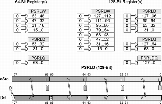
Mnemonic | P | PII | K6 | 3D! | 3Mx+ | SSE | SSE2 | A64 | SSE3 | E64T |
|---|---|---|---|---|---|---|---|---|---|---|
PSRLx |
|
|
|
|
|
|
|
|
| |
PSRLDQ |
|
|
|
|
MMX | psrl(w/d/q) mmxDst, count(#/mmx/m64) | [Un]signed | 64 |
SSE2 | psrl(w/d/q) xmmDst, count(#/xmm/m128) | [Un]signed | 128 |
" | psrldq xmmDst, count(#) | [Un]signed | 128 |
These multimedia and SIMD extension instructions are parallel operations that logically right shift each of the data bit blocks by a count of bits. Depending on the processor and the instruction, block sizes of 16, 32, 64, or 128 bits can be shifted by the specified count.
This is a divisor (2n) of unsigned values by shifting a 0 into the MSB of each packed value of the source aSrc (xmmSrc), which cause all bits to be shifted to the right and the LSB of each packed value being lost; the result is stored in the destination Dst (xmmDst). There is no Carry flag to save the bit. If the count indicating the number of bits to shift is more than packed bits - 1 — 15 for (Words), 31 for (Double words), 63 for (Quad words), or 127 for (Double Quad words) — then the destination will be typically set to a value of zero. This is most effective when used in an integer math function where multiple unsigned numbers need to be divided by 2n concurrently.
The C code simulating the functionality is almost identical to the Parallel Shift (Logical) Left instruction, previously discussed in this chapter, except in this case a different mask and a shift to the right are used instead. This should look very similar to you as previously reviewed in SLL; only the bold areas should be different!
Example 5-3. ...chap05protPRot.cpp
voidvmp_psrlB(uint8 * pbD, uint8 * pbA, uint count) { uint32 msk, *pD, *pA; pD=(uint32*) pvD; pA=(uint32*) pvA; count &= (8-1); // Clip count to data bit size-1msk = llMaskBD[count];*(pD+0) = (*(pA+0) & msk)>>count;
*(pD+1) = (*(pA+1) & msk)>>count; *(pD+2) = (*(pA+2) & msk)>>count; *(pD+3) = (*(pA+3) & msk)>>count; }
There are similarities between left and right logical shifting for the various processor instructions. The function shell code is very similar as lower versus upper bits are masked. The bits are shifted to the left versus to the right. In assembly code, one merely needs to substitute the correct instruction for the same functionality. In simulated C code, the correct mask needs to be chosen. Those instructions, along with their complement, are reflected in the following table.

Mnemonic | P | PII | K6 | 3D! | 3Mx+ | SSE | SSE2 | A64 | SSE3 | E64T |
SAR |
|
|
|
|
|
|
|
|
|
|
sar | rmDst(8/16/32/64), 1 | [Un]signed |
sar | rmDst(8/16/32/64), #(2n-1) | |
sar | rmDst(8/16/32/64), cl |
This instruction is a signed divide by 2nthat shifts the destination to the right and shifts the least significant bit (LSB) into the carry. The previous content of the carry is shifted out and lost, and a 0 is shifted into the most significant bit (MSB). The count indicating the number of bits to shift is invalid if it is greater than or equal to the width of data (2n). If you shift enough times you will empty the data, setting it to all 0's. If count = 0, then there is no shift and the destination and flags are not changed.
Flags: Carry = last bit shifted out, Zero = 1 if all destination bits are 0, thus destination = 0. If using the shift by 1, then Overflow is cleared to 0; else the Overflow is undefined. | ||||||
|---|---|---|---|---|---|---|
Flags | O.flow | Sign | Zero | Aux | Parity | Carry |
× | × | × | - | × | × | |
  datd  dd      32
  datw  dw      16
  datb  db      8

        mov     dx,1010010110100101b  ;0a5a5h carry=0
        mov     cl,2        ;  x4 = 22

        sar     datd,4      ; datd = 2 = 32 ÷ 16 = 32 ÷ (24)
        sar     dx,1        ; dx = dx × 2
                ; dx = 1101001011010010b 0d2d2h carry=1 Z=0 OF=0
        sar     eax,cl      ; eax = eax ÷ 4
This instruction is typically used as a signed divisor. Its use of the "sticky" MSB is great for use in generating masks. As an arithmetic shift retains the MSB while data is being shifted down, this "retained" bit is stuck. Thus, it sticks in position!
By using:
sar eax,31
a negative value sets EAX with all bits set to 1 and a positive value sets all 0's. With the use of masking bit logic, some algorithms could run faster due to not needing to branch. Investigate Chapter 11, "Branch-less," for more information.

Figure 5-3. Miscellaneous examples of data types being arithmetically shifted to the right by one bit
MMX | psra(w/d) mmxDst, count(#/mmx/m64) | Signed | 64 |
SSE2 | psra(w/d) xmmDst, count(#/xmm/m128) | Signed | 128 |
These multimedia and SIMD extension instructions are parallel operations that arithmetically right shift each of the data bit blocks by a count of bits. Depending on the processor and the instruction, block sizes of 16 or 32 bits can be shifted by the specified count.
This is a divisor (2n) by shifting the MSB, a "sticky" bit, of each signed packed value of the source aSrc (xmmSrc), causing all bits to be shifted to the right and the LSB of each packed value being lost; the result is stored in the destination Dst (xmmDst). There is typically no Carry flag to save the bit. If the count indicating the number of bits to shift is more than (packed bits - 1) — 15 for (Words) or 31 for (DWords) — then the destination will be typically set to the same value as the MSB, a value of zero. This is most effective when used in an integer math function where multiple signed numbers need to be divided by 2nconcurrently.
Pseudo vectors do not work well with this instruction due to the nature of the sticky bit. The technique demonstrated in a previous section of this chapter related to left shift discussed emulated vector processing by shifting followed by a logical AND, but it does not work with this instruction. If you really wish to investigate this further, my Vector Game Math Processors book has more information.
A multimedia extension instruction for a parallel rotation does not exist at this time. To rotate data is a process of shifting up the lower bits, shifting down the upper bits, masking, and blending by the specified count. It is recommended to only rotate by one instead of an immediate or by another register.

Mnemonic | P | PII | K6 | 3D! | 3Mx+ | SSE | SSE2 | A64 | SSE3 | E64T |
ROL |
|
|
|
|
|
|
|
|
|
|
rol | rmDst(8/16/32/64), 1 | [Un]signed |
rol | rmDst(8/16/32/64), #(2n-1) | |
rol | rmDst(8/16/32/64), cl |
This instruction shifts the destination to the left and the most significant bit (MSB) is rotated into the carry and the least significant bit (LSB). The previous content of the carry is lost. This is like a wagon wheel with the bits going counterclockwise around and around shooting off bits like sparks. The count indicating the number of bits to rotate is invalid if it is greater than or equal to the width of data (2n). If count = 0, then there is no shift and the destination and flags are not changed.
Flags: Carry = last bit rotated out of MSB, Zero = 1 if all destination bits are 0, thus destination = 0. If using a count of 1, then Overflow = the exclusive OR of the two MSBs before the rotate. (This is the same as the Carry XOR MSB after the rotate!) If the rotation is greater than 1, Overflow is undefined. | ||||||
|---|---|---|---|---|---|---|
Flags | O.flow | Sign | Zero | Aux | Parity | Carry |
× | × | × | - | × | × | |
   datd      dd      32
   datw      dw      16
   datb      db      8

             mov     dx,1010010110100101b 0a5a5h carry=0

             rol     dx,1
                   ; dx = 0100101101001011b 04b4bh carry=1 OF=1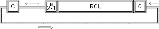
Mnemonic | P | PII | K6 | 3D! | 3Mx+ | SSE | SSE2 | A64 | SSE3 | E64T |
RCL |
|
|
|
|
|
|
|
|
|
|
rcl | rmDst(8/16/32/64), 1 | [Un]signed |
rcl | rmDst(8/16/32/64), #(2n-1) | |
rcl | rmDst(8/16/32/64), cl |
This instruction shifts the destination to the left, rotates the most significant bit (MSB) into the carry, and rotates the previous contents of the carry into the least significant bit (LSB). This is like a wagon wheel with an extra spoke. The count indicating the number of bits to rotate is invalid if it is greater than or equal to the width of data (2n). If count = 0, then there is no shift and the destination and flags are not changed.
Flags: Carry = last bit rotated out, Zero = 1 if all destination bits are 0, thus destination = 0. If using a count of 1, then Overflow = the exclusive OR of the two MSBs before the rotate. (This is the same as the Carry XOR MSB after the rotate!) If the rotation is greater than 1, Overflow is undefined. | ||||||
|---|---|---|---|---|---|---|
Flags | O.flow | Sign | Zero | Aux | Parity | Carry |
× | × | × | - | × | × | |
  datd     dd      32
  datw     dw      16
  datb     db      8

           mov     dx,1010010110100101b 0a5a5h carry=0

           rcl     dx,1
                 ; dx = 0100101101001010b 04b45h carry=1 Z=0 OF=1
This is effective for the shifting of monochrome data or masking planes, effectively making an image appear to move to the right.
; actual nibble mask    f00000000000ffff00e300080ff00ef7
Msk:    dd      00000000fh,0ffff0000h,080003e00h,07fe00ff0h


$Beg:   mov     esi,offset Msk+(16-4)
        add     edi,16-4
        mov     ecx,3-1               ; 4 arguments

        mov     eax,[esi]
        shl     eax,1
        mov     [edi],eax

$L1:    mov     eax,[esi]
        rcl     eax,1
        mov     [edi],eax
        sub     edi,4
        sub     esi,4
        dec     ecx
        jne     $L1
Mnemonic | P | PII | K6 | 3D! | 3Mx+ | SSE | SSE2 | A64 | SSE3 | E64T |
ROR |
|
|
|
|
|
|
|
|
|
|
ror | rmDst(8/16/32/64), 1 | [Un]signed |
ror | rmDst(8/16/32/64), #(2n-1) | |
ror | rmDst(8/16/32/64), cl |
This instruction shifts the destination to the right and rotates the least significant bit (LSB) into the carry and the most significant bit (MSB). The previous content of the carry is lost. This is similar to a wagon wheel with the bits going clockwise around and around shooting off bits like sparks. The count indicating the number of bits to rotate is invalid if it is greater than or equal to the width of the data (2n). If count = 0, then there is no shift and the destination and flags are not changed.
Flags: Carry = last bit rotated out, Zero = 1 if all destination bits are 0; thus destination = 0. If using a count of 1, then Overflow = the exclusive OR of the two MSBs after the rotate. If the rotation is greater than 1, Overflow is undefined. | ||||||
|---|---|---|---|---|---|---|
Flags | O.flow | Sign | Zero | Aux | Parity | Carry |
× | × | × | - | × | × | |
  datd  dd      32
  datw  dw      16
  datb  db      8

        mov     dx,1010010110100101b 0a5a5h carry=0

        ror     dx,1
              ; dx = 1101001011010010b 0d2d2h carry=1 Z=0 OF=0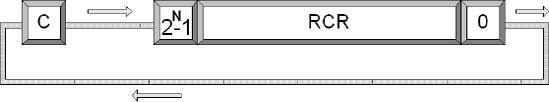
Mnemonic | P | PII | K6 | 3D! | 3Mx+ | SSE | SSE2 | A64 | SSE3 | E64T |
RCR |
|
|
|
|
|
|
|
|
|
|
rcr | rmDst(8/16/32/64), 1 | [Un]signed |
rcr | rmDst(8/16/32/64), #(2n-1) | |
rcr | rmDst(8/16/32/64), cl |
This instruction shifts the destination to the right and rotates the least significant bit (LSB) into the carry. The previous content of the carry is rotated into the most significant bit (MSB). This is like a wagon wheel with an extra spoke. The count indicating the number of bits to rotate is invalid if it is greater than or equal to the width of the data (2n). If count = 0, then there is no shift and the destination and flags are not changed.
Flags: Carry = last bit rotated out, Zero = 1 if all destination bits are 0; thus destination = 0. If using a count of 1, then Overflow = the exclusive OR of the two MSBs after the rotate. If rotation is greater than 1, Overflow is undefined. | ||||||
|---|---|---|---|---|---|---|
Flags | O.flow | Sign | Zero | Aux | Parity | Carry |
× | × | × | - | × | × | |
  datd  dd      32
  datw  dw      16
  datb  db      8

        mov     dx,1010010110100101b 0a5a5h carry=0

        rcr     dx,1
; dx = 0100101101001010b 0d2d2h carry=1 Z=0 OF=1Mnemonic | P | PII | K6 | 3D! | 3Mx+ | SSE | SSE2 | A64 | SSE3 | E64T |
|---|---|---|---|---|---|---|---|---|---|---|
BSF |
|
|
|
|
|
|
|
|
|
|
bsf | rDst, rmSrc(16/32/64) | [Un]signed |
This instruction scans the source for the least significant bit (LSB); if found, it sets the destination to the index (0...n). If the source is set to 0, the destination is undefined.
Flags: If the source is zero, then the Zero flag is set to 1; else it is set to 0. | ||||||
|---|---|---|---|---|---|---|
Flags | O.flow | Sign | Zero | Aux | Parity | Carry |
- | - | × | - | - | - | |
                                  ; ebx = some value
        mov     ecx,0             ; Preset to zero in case ebx is 0.
        mov     ebx,eax
        bsf     ecx,ebx           ; ecx contains the bit setting
        shr     ebx,cl            ; Down shift the data
Note
Preset the BSF destination to zero if the source is not guaranteed to be not zero (unless you plan to branch if zero).
BSR destination, source
Mnemonic | P | PII | K6 | 3D! | 3Mx+ | SSE | SSE2 | A64 | SSE3 | E64T |
BSR |
|
|
|
|
|
|
|
|
|
|
bsr | rDst, rmSrc(16/32/64) | [Un]signed |
This instruction scans the source for the most significant bit (MSB); if found, it sets the destination to the index (0..n). If the source is set to 0, the destination is undefined.
Flags: If the source is zero, then the Zero flag is set to 1; else it is set to 0. | ||||||
|---|---|---|---|---|---|---|
Flags | O.flow | Sign | Zero | Aux | Parity | Carry |
- | - | × | - | - | - | |
Here is an obvious use for an 80×86 instruction versus generic C code. In various compression and data packing methods, it is sometimes necessary to find out the maximum number of bits needed to store a value from a list of values, such as how many bits it takes to compress a piece of data. For example, if we take a histogram of all the colors in a bitmap and the highest count is 53 colors (53 - 1 = 52) (034h) (110100b), then it would take 6 bits to store it:
The following calculates the number of bits needed to store an unsigned value.
 uint CountBits(uint val)
 {
       uint nCnt;

 #if 01
              // Use this! VERY MUCH FASTER than a bit scanner!
              // Reverse scan for MSB
       __asm  {
       mov    eax,0                 // Set to zero, in case val is zero.
              bsr eax,val           // N...0 Bit index
              inc eax               // N+1...1 # of bits
              mov nCnt,eax
       };
 #else
   uint nBit = 0x80000000;
   nCnt = 32;

   while ((nCnt > 1) && (0 == (nBit & val)))
   {
        nCnt--;
        nBit >>= 1;
   }
 #endif

 return nCnt;
So if you had numerous numbers to crunch, which of the code snippet algorithms just shown would you rather utilize? A couple instructions of assembly in the upper conditional code or looping up to 31 times maximum for each 32-bit integer value as shown in the lower conditional code?
There is a problem when writing graphics-based applications for Win32. If graphics is 256 color, then the palette is a table lookup. If 24-or 32-bit true color, then the RGB bit orientation is standardized, but if in 16-bit hi-color, then you have a problem. There is no standard, however, although there seem to be two orientations: {5:5:5} and {5:6:5}. But which does that card you are trying to run your application on really use? Direct Draw solved this problem, as you can request the bit and mask information, but what if you are writing a Windows application running under GDI, or a DOS application, or whatever? If your source art is 256 color, you would need to create a conversion table to match your graphics mode. If you have Targa art files that are {5:5:5} and the graphics card is {5:6:5}, you would need to detect this and compensate for it. You will have to paste this code section into your own C code. So, my apologies to those only interested in pure assembly.
Tip
These days there is typically not a good reason for pure assembly code. It is a waste of programming resources.
Sorry if I am offending any of you speed freaks. I personally happen to like to squeeze every last drop of clock cycle out of my CPU, but development projects are about balance: code size vs. code speed. Project budget vs. time constraints. There are also portability issues, but these are usually resolved through abstraction where function pointers are used to vector to generic C or custom assembler based upon processor requirements.
// Color Masking information

typedef struct RGBInfoType
{
    uint RedMask;
    uint GreenMask;
    uint BlueMask;
    uint RedShift;
    uint GreenShift;
    uint BlueShift;
    uint zRedShift;
    uint zGreenShift;
    uint zBlueShift;
} RGBInfo;
// If a fixed palette then get 16/24/32-bit color masking information.
// hDC = (HDC) DC to window
// wgInfo = (BITMAPINFOHEADER)
// nDepth = BitsPerPixel;
HBITMAP hBitmap;
byte *pBMap;
RGBInfo info;
hBitmap = CreateDIBSection(hDC, (BITMAPINFO *) &wgInfo,
DIB_PAL_COLORS, (VOID **) &pBMap,
(HANDLE) NULL, (DWORD) NULL);
if (hBitmap != NULL)
{
HBRUSH hBrush;
RECT rect;
rect.left = rect.top = 0;
rect.right = rect.bottom = 2;
// Test for Red Mask bits
hBrush = CreateSolidBrush(0x000000ff); // 0x00bbggrr
FillRect(hDC, &rect, hBrush);
info.RedMask = *(DWORD *)(pBMap);
// Test for Green Mask bits
hBrush = CreateSolidBrush(0x0000ff00); // 0x00bbggrr
FillRect(hDC, &rect, hBrush);
info.GreenMask = *(DWORD *)(pBMap);
// Test for Blue Mask bits
hBrush = CreateSolidBrush(0x00ff0000); // 0x00bbggrr
FillRect(hDC, &rect, hBrush);
info.BlueMask = *(DWORD *)(pBMap);
// Now analyze
gfxGetColorMasks(nDepth, &info);
}Now we come to the fun part. Normally we would only call these function pairs once during program initialization, so it does not need to be very fast. However, the BSF and BSR instructions are two that do not translate well to C code. They would need a slowpoke bit-shifting loop, so I thought it would be a good example and a function that you would be able to use in your own graphic applications.
  ; Color masking information

  RGBInfo STRUCT 4
      RedMask    dd   0     ; Red color mask
      GreenMask  dd   0     ; Green color mask
BlueMask dd 0 ; Blue color mask
; These bits are used to shift the bits into position
RedShft dd 0 ; Red shift bits up
GreenShft dd 0 ; Green shift bits up
BlueShft dd 0 ; Blue shift bits up
; These bits are used to reduce the bits needed
zRedShft dd 0 ; Red shift bits down
zGreenShft dd 0 ; Green shift bits down
zBlueShft dd 0 ; Blue shift bits down
RGBInfo ENDS
; Get fixed palette color mask information
;bool gfxGetColorMasks(uint nDepth, RGBInfo *pInfo)
public gfxGetColorMasks
gfxGetColorMasks proc near
push ebp
mov ebp,esp
mov eax,[ebp+arg1] ; nDepth - Get pixel depth
push esi
shr eax,3 ; n÷8
push ebx
mov ebx,RGBMsks[eax*4] ; Get Premask
mov esi,[ebp+arg2] ; pInfo - Get (RGBInfo *)
test ebx,ebx
jz $Xit ; false (failure)
; Save masks. Get position of first and last
; bits in mask for each color!
; Green bits
mov eax,(RGBInfo PTR [esi]).GreenMask
and eax,ebx ; AND with mask
mov (RGBInfo PTR [esi]).GreenMask,eax
bsf ecx,eax ; get LSB set to 1
bsr edx,eax ; get MSB set to 1
mov (RGBInfo PTR [esi]).GreenShft,ecx
sub edx,ecx
add edx,-7
neg edx
mov (RGBInfo PTR [esi]).zGreenShft,edx
;Blue bits
mov eax,(RGBInfo PTR [esi]).BlueMask
and eax,ebx
mov (RGBInfo PTR [esi]).BlueMask,eax
bsf ecx,eax ; get LSB set to 1
bsr edx,eax ; get MSB set to 1
mov (RGBInfo PTR [esi]).BlueShft,ecx
sub edx,ecx
add edx,-7
neg edx mov (RGBInfo PTR [esi]).zBlueShft,edx
;Red bits
mov eax,(RGBInfo PTR [esi]).RedMask
and eax,ebx
mov (RGBInfo PTR [esi]).RedMask,eax
bsf ecx,eax ; get LSB set to 1
bsr edx,eax ; get MSB set to 1
mov (RGBInfo PTR [esi]).RedShft,ecx
sub edx,ecx
add edx,-7
neg edx
mov (RGBInfo PTR [esi]).zRedShft,edx
mov eax,1 ; true (success)
$Xit: pop ebx
pop esi
pop ebp
ret ; Return eax
gfxGetColorMasks endpWith a 32-bit data element size, what is the result of a logical right shifting of the following data by 34 bits? With an arithmetic right shift? With a logical left shift?
0xB83DE7820
Write a function to count the number of bits to contain a signed value.
Write a packed 16× 8-bit SAR, using pseudo vector code.
Write a packed 16× 8-bit SAR, using SIMD instructions.
Write a packed ROL using SIMD.
8-bit
16-bit
32-bit
Write a packed ROR using SIMD.
8-bit
16-bit
32-bit