
Appendix A
Core Concepts
This section is intended to give you some quick reminders and further details about various functions, nodes, and systems and should be viewed in conjunction with the relevant sections of the book.
We have put these in the order that we might typically need to operate in a game. An input (Key and Gamepad Inputs) or event (Events and Triggers) may trigger a sound event. In order to get events we need to manipulate and place triggers (Manipulating Actors) and reference these from within the Level Blueprint (Referencing in-game Actors within Blueprints). There might be variables that influence the sound so we need to look at these (Variables, Parameters, Numbers and Arrays) and how to manipulate them (Transforming and Constraining Variables and Parameters). Depending on the variable (Evaluating Variables and Parameters) we may want to decide for certain things to happen (Routing Decisions and Events) to produce changes in our sounds (Controlling Audio Components and Sound Cue Nodes). We will also want to monitor what is happening to make sure our systems are working as intended (Console Commands).
Key and Gamepad Inputs
The Bindings menu (Edit/Project Settings/Input/Bindings) is used to map specific keys and gamepad axes and events to commands that can then be called within Blueprints.

You can set these up as you like for the input methods you want to use and for any events and actions you need within your game. Action mappings are for key or button presses and releases (e.g., Spacebar for jump), while axis mappings are for inputs with a continuous range (e.g., joystick for movement). As an example, the fire action is mapped to both the LMB and the right trigger of a gamepad. This can be called within a Blueprint using the <InputAction Fire> event.
Once established in the Bindings menu, you can create events for these in Blueprints through the Blueprint ![]() Graph Action Menu. Keyboard input events are all set up by default.
Graph Action Menu. Keyboard input events are all set up by default.

Events and Triggers
You can only have one instance of an event within a Blueprint, so if you need multiple things to occur on a specific event, you will need to either chain them sequentially or use <Sequence> nodes.
As well as the input events configured within the Bindings menu, you can also make use of the following:
<Event Begin Play>
Called when the Actor or Blueprint is first initialized (in the case of the [Level Blueprint], this would be when the game starts).
<Event Tick>
Called on every frame while the game is being played. This event also returns the DeltaTime (the time between frames), which is used in conjunction with nodes such as <FInterp To>.
These are assigned to a specific key and called when that key is pressed or released. By default these events are set to consume input, which means if you have the same key in multiple Blueprints (i.e., level and character), only one of them will work.
<Event Any Damage>
Called when the Actor takes any kind of damage. This event returns the amount of damage taken (Damage), the Damage Type, and the name of the Actor that caused the damage.
Depending on the type of Actor, there will be other events that are available, for example the player character has <Event On Landed> and <Event On Start Crouch>.
Trigger Touch from Overlap or Hit
With a [Trigger] Actor selected in the ![]() Viewport, you can right-click in the
Viewport, you can right-click in the ![]() Event Graph and create the following:
Event Graph and create the following:
<Event Actor Begin Overlap>
Called when the collision volume of an Actor overlaps with that of another Actor.
- This requires the collision property to be set to overlap.
<Event Actor End Overlap>
Called when the overlap between two Actors ends (i.e., their collision volumes no longer overlap).
- This requires the collision property to be set to overlap.
<Event Hit>
Called when collision volumes set to block collide with each other.
- This requires the collision property to be set to block.
Trigger Use
In order to trigger events from key or controller inputs anywhere in the level, we could just create a <Key Event> in the [Level Blueprint] and link it straight to a <Play Sound Attached> (or other function), however this would work globally (i.e., wherever we were in the level). Instead, we might we want this input to work only when the player is actually standing next to the relevant Actor.

In order to do this, we use a <Gate> node that is opened and closed by the [Trigger] around the button. This way the <Key Event> E will not be allowed through to trigger the sound unless the player is in proximity to the button.
Find the <Key Event> E by searching the ![]() Graph Action Menu for “E Key”.
Graph Action Menu for “E Key”.
Trigger Use and Release
This enables us to set up the Released output of a <Key Event> as well as the Pressed. Again, to avoid this occurring globally we control a second <Gate> with the overlap events from a [Trigger].

Manipulating Actors
You use the transform widgets to manipulate Actors within the editor—you can select the different widgets from the selection menu across the top of the Viewport or by pressing the Spacebar to cycle through them.

Translate Widget
This enables us to move an Actor around within the world. You can click and drag on any of the arrows to move in that axis or on the crossbeams of the arrows to move in two axes simultaneously.

Rotate Widget
This enables us to rotate an Actor around any of the three axes within the world.

Scale Widget
This enables us to scale an Actor along any of the three axes within the world. You can click and drag on any of the boxes to scale along that axis, on the crossbeams to scale in two axes simultaneously, or on the white box to scale along all three.

When using the transform widget, any adjustments you make will be snapped according to the snapping settings. You can change these from the selection menu across the top of the Viewport.
You can also enter transform values directly into the Actor’s ![]() Details panel.
Details panel.

Referencing In-game Actors within Blueprints
If you select an Actor in the level, and then right-click in the Blueprint, you can create a reference to that Actor that you can then use to call functions and set variables.

Handily, you can also create functions and nodes that are preconnected to this reference. For example if you have an Actor selected and then find “Get Root Component”, it will automatically add a reference to the Actor hooked up the <Get Root Component> node.

This works for lots of things—for example if you have an [Ambient Sound] selected in the level and you create a <Play> node, it will create a reference to the Actor and hook it up to the <Play> node.
Variables, Parameters, Numbers, and Arrays
Variables are used within Blueprints to keep track of game states and events and to drive other systems (e.g., the volume of a music track). There are a variety of different variable types, but the most common are ints, floats, arrays, bools, and vectors. Ints are integers (whole numbers), floats are floating point numbers (with decimal points), Bools are Boolean variables (True / False), and vectors describe direction movement or locations. Remember that in the Unreal Engine (and all other code) indices start at 0, not 1 (i.e., the first output of a switch is output 0).
You can create variables from the ![]() MyBlueprint panel by clicking on the + icon in the Variable section. A new variable will be created, and you can then set its Name and Type through its
MyBlueprint panel by clicking on the + icon in the Variable section. A new variable will be created, and you can then set its Name and Type through its ![]() Details panel.
Details panel.

If you compile the Blueprint, you can then set a default value for that variable (again, in the ![]() Details panel).
Details panel).
Once you’ve created your variable, you can drag into the ![]() Graph window and either create a <Get> or <Set> node, depending on what you want to do. Once added, you can no longer change its variable type. (You also can automatically create <Get> or <Set> by holding Ctrl or Alt as you drag into the
Graph window and either create a <Get> or <Set> node, depending on what you want to do. Once added, you can no longer change its variable type. (You also can automatically create <Get> or <Set> by holding Ctrl or Alt as you drag into the ![]() Event Graph.)
Event Graph.)

This can then be connected up into your larger Blueprint systems.
Each type of variable is a different color, as are the connections that come from them when using the <Get> nodes. This makes it very easy to see what is going on within your Blueprints and what type of variables you are using.

The inputs to nodes are also color-coded in the same way.

If at any point you’re not sure what type of variable to create, you can right-click an input or output port on a node and select Promote To Variable. This will automatically create a new variable of the correct type for whatever it is that you’ve clicked on.

You can change an existing variable node to a new one by dragging the new variable from the ![]() MyBlueprint panel on to an existing variable node. Depending on whether you drag the new variable on to the left or right side of the node, you can either change the variable being read or assign the new variable to be that of the old one.
MyBlueprint panel on to an existing variable node. Depending on whether you drag the new variable on to the left or right side of the node, you can either change the variable being read or assign the new variable to be that of the old one.


The get and set functions for arrays are slightly different. Any variable type can be turned into an array simply by clicking on the Make Array button next to the variable name.

Because an array is a collection of variables stored as a list, when we want to get or set something within the list, we have to use the index. Remember that the first item in an array has an index of 0, the second item has an index of 1, and so on.
To get an array item, we have to create a reference to the array and then get a given index from that.

To set an array element, we again have to create a reference to the array and then define the value of the item at a given index.

Transforming and Constraining Variables and Parameters
Variables and parameters from the game system do not always come in a range of numbers that are useful to us in terms of controlling audio (or other aspects of game systems), so there are a variety of nodes that allow us to transform these into more usable numbers. Some of these are variable type specific (i.e., only come in float varieties), but others come in different variable types.
<Normalize to Range>
This takes an incoming range of numbers and normalizes them (i.e., converts the incoming range to an outgoing range of 0.0–1.0). You have to define the Range Min and Range Max of your incoming values. If your incoming range exceeds the Range Max value, then the output will exceed 1.0 (and vice versa if the range goes below the Range Min value, so you may want to <Clamp> the values as well).
<Map Range>
This takes a defined incoming range of numbers (in range A–in range B) and maps them on to a defined outgoing range of numbers (out range A–out range B). You can also do this within a Sound Cue’s -Continuous Modulator- using the Min/Max Input/Output settings.
<Absolute>
This returns the absolute (i.e., positive) value of the incoming number (used to convert negative numbers to positive numbers). You can also do this within a Sound Cue’s -Continuous Modulator- by changing the Param Mode within its ![]() Details panel.
Details panel.
<Clamp>
This is used to ensure that a range of numbers cannot exceed a given range. The Value input is clamped between the Min and Max range values. This is a useful node when dealing with physics and impact velocities, as it can be used to constrain the occasional extreme value.
<In Range>
This node produces a Boolean output depending on whether the incoming Value input is between the Min and Max range values.
<FCeil>
This takes a float input and rounds it up to the nearest integer (e.g., 2.3 would become 3).
<Floor>
This takes a float input and rounds it down to the nearest integer (e.g., 2.8 would become 2).
This takes a float input and rounds it to the nearest integer (e.g., 2.3 would become 2 and 2.8 would become 3).
There are also a variety of <To> nodes that will convert from one variable type into another.
- Quite often these can be created automatically if you’re trying to connect one variable type to another.
If you wanted to interpolate (i.e., create a changing series of values) between one value and another (e.g., if you wanted to create a transition movement for a camera when switching between first-person and third-person views), then there are a number of nodes that can do this for you—<FInterp To>, <FInterp To Constant>, and <Ease>. There are also variants of these objects for colors, rotators, vectors, and transforms.
Reading through Curves
The ability to take a linear range of numbers but then transform them by using them to read through user-defined curves is very useful as we have seen in Chapter 02 for parameterized sound, Chapter 04 for layers of parallel music, Chapter 07 for impact velocities to different sounds (including footsteps speed), and Chapter 09 for weapons detail over distance.
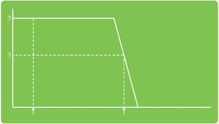
Applying a curve to the linear parameter of volume adjustments in UE4 (0.0–1.0) is particularly useful since, unlike the volume controls in your DAW, the volume scaling does not by default reflect the logarithmic nature of loudness perception. As you can see in the rough comparison illustrated below, a 0.5 volume multiplier will indeed result in a -6dB drop and so will be perceptually at half the volume as expected, but as we get into the lower range of multipliers, smaller incremental changes have a more dramatic effect on perceived volume differences.

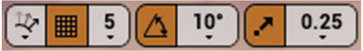
Having created a {Curve} asset in the content browser (New/Miscellaneous/Curve Float), you can double-click it to open the ![]() Curve Editor. Create a new point with Shift and click, click and drag points to move, and use the mouse wheel to zoom in/out. Click and hold RMB to move the view around, and right-click on points to change the curve type.
Curve Editor. Create a new point with Shift and click, click and drag points to move, and use the mouse wheel to zoom in/out. Click and hold RMB to move the view around, and right-click on points to change the curve type.

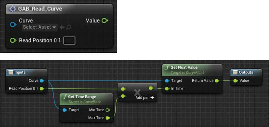
When you add your curve asset to a curve variable in the Blueprint, you can <Get> this variable and drag out from it to <Get Float Value> (compile the Blueprint first).
The In Time will make the node read and output the value of the curve at that position on its X-axis (time is just the name for this axis, but you can treat it simply as a set of values). This means that we can use curves as a kind of lookup table for values and control the response to game parameters by changing the shape of the curve.

This is fine if the range of time values you are reading matches the time range of the curve, but another useful thing to do sometimes is to be able to map the time range of the curve you have created onto values between 0.0–1.0. This way the curve is acting more like a percentage scale of the input values, and you can reuse the curve for a number of different input ranges. We have created the Blueprint macro [GAB_Read_Curve] to do this. This gets the time range of the curve. This is taken from 0.0 to the position of the last defined key point. By finding the value of the end point of the curve, we can now multiply this by our read position (0.0–1.0) to map the values to a 0.0–1.0 range.
Evaluating Variables and Parameters
There are plenty of times when you need to evaluate a variable and then do something based on the result of this evaluation. The objects that are available for evaluation are (these come in a variety of variable types):
This outputs a Boolean value depending on whether input A is greater than input B.
Greater Than or Equal To (>=)
This outputs a Boolean value depending on whether input A is greater than or equal to input B.
Less Than (<)
This outputs a Boolean value depending on whether input A is less than input B.
Less Than or Equal To (<=)
This outputs a Boolean value depending on whether input A is less than or equal to input B.
Equal To (==)
This outputs a Boolean value depending on whether input A is equal to input B.
Not Equal (!=)
This outputs a Boolean value depending on whether input A is not equal to input B.
<Nearly Equal>
This outputs a Boolean value depending on whether input A is within the Error Tolerance of input B.
You can also evaluate the results of evaluations if you want (like we did with the inventory section in Chapter 06 on dialogue). These objects only take Boolean inputs.
<AND>
This outputs True if both input values are True.
<OR>
This outputs True if either or both of the input values are True.
<XOR>
This outputs True if and only if one of the input values is True.
Routing Decisions and Events
You often may want to pass exec signals to different parts of your Blueprints based on the value of variables or the results of your evaluations.
This passes the exec signal to either its True or False outputs based on the value of the controlling Boolean Condition.
<Gate>
The Enter signal is only allowed to pass through to the Exit if the <Gate> is open. You can Open or Close the
<Gate> using it’s inputs as well as using the Toggle input to toggle it’s open/close state.
<Switch>
There are a variety of these, but the most useful is probably the <Switch On Int>. This routes the incoming exec signal to the output defined by the Selection input (an integer).
<CompareFloat>/<CompareInt>
This is a triggerable node (i.e., it has an exec input), and it compares input A against input B to output an exec from either its >, ==, or < outputs depending on the result of the evaluation. This is actually a macro containing > and < nodes and <Branch> es to route the exec signal based on the evaluations.
<Select>
Unlike the other routing nodes, this one doesn’t route an exec signal. Instead it routes variables. You can connect any kind of variable to its Option inputs, and the Index input selects which one gets passed through.
<Sequence>
This takes an exec signal and routes it out of multiple outputs in order.
<FlipFlop>
This takes an exec signal and alternately routes it from output A, then output B, then A, etc.
<MultiGate>
This object will pass the incoming exec signal to its output pins in order on consecutive triggers. You can also set it to be random if you want. It also has a Loop option. You can also override Start Index by connecting an integer variable to the relevant input.
<DoOnce>
This will only output an exec signal once (useful for preventing repeated retriggers). It can be reset using the Reset input.
This is useful for reading through or setting the entirety of an array in one go.
Custom Events
You can set up your own <Custom Event>s within a Blueprint—these can be used to create interactions between different Blueprints or just to reduce the number of connections within a single Blueprint. If you want to reduce the connection clutter on your screen, you can use a <Remote Event> to call a <Custom Event>—simply set them up to have the same name.

If you want to use them to create interactions between different Blueprints (say you want to call a function within your player Blueprint from the level Blueprint), then you first need to set up the <Custom Event> in the player Blueprint. Make sure you compile the Blueprint.

Then in the level Blueprint, you need to create a reference to the player character using <Get Player Character>, and then <Cast> this to the class of your player character (e.g., [MyCharacter]) so that you can access any events defined within its Blueprint. Then drag off the As My Character output of the <Cast> node and search for the name of your event. You can then use any kind of event within your level Blueprint to trigger the <Cast> and in turn the event within your player Blueprint.

Controlling Audio Components
You can dynamically control the playback of sounds to respond to game parameters or variables with a variety of Blueprint nodes.

These can target audio components from references to in-game [Ambient Sound]s or from <Play Sound Attached> nodes. Drag out from the blue Return Values to select them from the actions palette.

The <Set Pitch Multiplier>, <Set Volume Multiplier>, <Set Sound>, and <Set UISound> apply directly, while the <Set Boolean Parameter>, <Set Float Parameter>, <Set Integer Parameter>, and <Set Wave Parameter> are given names (In Name) that correspond to names allocated in various Sound Cue nodes.

<Set Boolean Parameter>
Sets the -Branch- node for selecting sounds in response to True or False conditions.
<Set Float Parameter>
Sets the -Continuous Modulator- node for controlling volume or pitch, or a -Crossfade By Parameter- node for controlling crossfades.
<Set Integer Parameter>
Sets the -Switch- node for selecting sounds based on the value of an integer.
Sets the -Wave Param- node for swapping out sounds.
When an event triggers any of these <Set> nodes, they apply immediately to the currently playing sound, therefore you should typically trigger changes at the same time as triggering the sound itself in order to avoid the currently playing sound being interrupted.

An exception to this might be the <Set Float Parameter> (targeting the -Continuous Modulator- or -Crossfade by Parameter-) where you might continuously update the parameter to apply volume or pitch changes via an <Event Tick> or Update from a <Timeline>.

You might also update the parameters of a <Set Pitch Multiplier> or <Set Volume Multiplier> in a similar fashion.

You can only have one <Event Tick> in a Blueprint, so you would either route this through several nodes until it reached your <Set> node (ideally) or use a <Sequence> node to get multiple versions directly to different places. Be aware that systems driven by an <Event Tick> can have a significant performance impact, so always consider alternatives and use only when absolutely necessary.
Sound Cue Nodes
Navigating in Sound Cues
- LMB—Click to select, click and hold to drag
- RMB—Click and hold to move the screen around
- Ctrl + LMB—Select multiple items
- Shift + LMB—Marquee select (this allows you to draw a rectangle and will select the items within it)
Click and drag wires between the inputs and outputs to connect up the systems or use Alt + click to delete connections.
-Output-
This contains the global properties of the Sound Cue itself. Here you can also set the attenuation settings for the cue, together with the overall Volume and Pitch multipliers, the Sound Class, and the playback rules (regarding how many instances of the sound can be played back simultaneously).
-Attenuation-
This node determines how the sound will attenuate over distance and spatialize. If your Sound Cue has an -Attenuation- node, then you can also access these settings from the Properties (right-click) of the Sound Cue in the ![]() Content Browser.
Content Browser.
This node allows you to set a parameter outside of the cue that will control which branch it plays depending on if the parameter is True or False (see p 428 and the Controlling Sound Cues section below).
-Concatenator-
This will chain together a series of sounds attached to its input—as soon as the first has finished playing, it will play the next input, etc.
-Continuous Modulator-
This can be used to vary the pitch and/or volume of a sound in response to game variables such as the velocity of vehicles. There are settings within the -Continuous Modulator- that allow some transformation of the incoming variables, such as mapping them to a given range or restricting them to absolute (positive) values (see the ‘Controlling Sound Cues’ section below).
-Crossfade by Distance-
Two or more sounds can have volume envelopes applied depending on their distance from the sound source
-Crossfade by Param-
You can use an external parameter to control the crossfade between two or more sounds
-Delay-
A delay will instigate a sound at a random time between its min and max settings
-Dialogue Player-
This node allows you to play certain sounds depending on which character is speaking or listening
-Doppler-
This node will apply a Doppler shift type effect to the cue
-Enveloper-
This node allows you to apply volume or pitch envelopes to your sounds
-Group Control-
This will choose a different input sound to play depending on how many instances of the first input sounds are playing
This will loop the system. It is not for looping sounds themselves, which is done with a looping wave player
-Mature-
This designates the sound as belonging to the mature category for reasons of age appropriateness.
-Mixer-
The volume level of two or more inputs can be set using this node
-Modulator-
This node can vary the volume or pitch of a sound with fixed or randomized settings
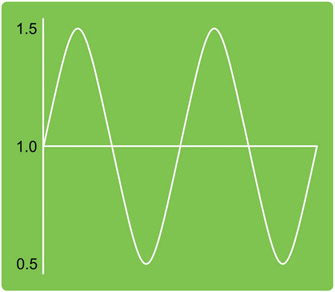
-Oscillator-
This oscillator can be applied to the pitch and/or volume of a sound
- Modulate Volume/Modulate Pitch: Choose to modulate either or both
- Amplitude Min/Max: The amplitude of the oscillator’s modulation (following a sine wave pattern)
- The wave is centered by default around 1.0, so if this amplitude were set to 0.5, you would get a range of values from 0.5 to 1.5. There is both a min and max setting, so you can also randomize this parameter between those two values.
- Center Min/Max: You can offset the center of the modulation so that, for example, the sound does or does not drop to complete silence when at the lowest point of its cycle.
- Frequency Min/Max: This value is twice the frequency of the sine wave’s modulation in Hz. Min/max fields are for the randomization of this value.
- Offset Min/Max: Where the sine wave starts in its cycle is referred to as phase. This offset value allows you to shift the phase of the cycle. This value is multiplied by 2*Pi. Min/max fields are for randomization.
-Random-
This will randomly choose between two or more inputs to play
-SoundClass-
This node can be used to set the Sound Class of a sound
-Switch-
You can use an external parameter to choose which input of a switch is played (see the Controlling Audio Components section above).
-WaveParam-
This parameter refers to the name of a Sound Wave and can be used to swap out the sounds played within a cue at runtime (see the Controlling Audio Components section above).
-Wave Player-
This node is the container for your Sound Waves. It can be set to loop the sound
Console Commands
¬ key (Windows) ~ key (Mac)
The quickest way to use the Console is to start typing the command you want. You will then see a list of matching commands appear. Use the up and down arrow keys to choose your command and then press the Tab key to add it to the command line. Now press Return.
If you use the up arrow key before typing anything, then you can scroll through a list of your previous Console commands.
- stat audio: Gives you lots of useful information, including crucially the number of any wave instances dropped

- stat sounds/stat sounds off: Lists all currently playing sounds

You can also sort these in a variety of ways.
- stat sounds-debug: See the attenuation settings of ambient sounds in the game (the sound assets must have debug enabled in their
 Details panel)
 - stat soundcues/stat soundcues off: Lists currently playing Sound Cues
- stat soundwaves/stat soundwaves off: Lists currently playing Sound Waves
- listwaves: Prints to output log (Window/Developer Tools/Output Log)
- stat reverb: Lists the active reverb effect
- listsounddurations: Outputs a list of all Sound Waves and their durations
- listwaves: Lists all WaveInstances and whether they have a source in game
- testLPF: Sets the LPF to the maximum for all sources
- testLFEBleed: At the moment this does the same as TestLPF
- teststereobleed: Sets stereo bleed to maximum on all audio sources for testing
- stat soundmixes: Shows a list of active Sound Mixes
- listsoundclasses: Shows a list of Sound Classes and the number of sounds in each class
- showsoundclasshierarchy: Shows a list of all your Sound Classes and any parent/child relationships within them
- setbasesoundmix: Allows you to trigger a named Sound Mix
- modifysoundclass: Allows you to modify the volume of a specified Sound Class—type the name of the Sound Class, then “Vol= (***)”
- isolatereverb: Isolates only the reverb
- isolatedryaudio: Removes any reverb effect
Others
Matinee
After creating a [Matinee] Actor in the level, you can create a reference to this Actor in the [Level Blueprint] to control the Matinee.

In the Matinee’s ![]() Details panel, you can also set it to Play on Level Load and to be Looping if you want it to start automatically.
Details panel, you can also set it to Play on Level Load and to be Looping if you want it to start automatically.
Creating a <Matinee Controller> in the Blueprint allows you to get notifications of when the Matinee finishes (as defined by the red marker in the Matinee timeline) and any events that you might add to an Event Track.
When using a Matinee for cinematics, don’t forget to check the options in the Cinematic section of its ![]() Details tab.
Details tab.
Attaching Actors to other Actors
Attaching Actors to other Actors is a useful way of ensuring that things that should move together do so. For example you might want to attach an [Ambient Sound] to a plane mesh that is moving across the level. Rather than having to set up both Actors’ movements within a Matinee, we can just set up the plane and then attach the sound to the plane.
The easiest way of doing this is via the ![]() World Outliner tab. Select the Actor you wish to attach (e.g., the sound), right-click and go to Attach. You can then search for the Actor you wish to attach to (e.g., the plane).
World Outliner tab. Select the Actor you wish to attach (e.g., the sound), right-click and go to Attach. You can then search for the Actor you wish to attach to (e.g., the plane).
You need to make sure that both the attachee and the attacher are set to be movable Actors (via the ![]() Details tab).
Details tab).
You can also attach Actors to each other via Blueprints, using either the <Attach To>, <Attach Actor To Actor>, or <Attach Actor To Component> nodes (which one you use will depend on how you want the attachment to work, but most likely you’d use <Attach Actor To Actor>).

You define the Target (the Actor to be attached), the In Parent Actor (the Actor you’re attaching to), the Socket Name (if you’re using sockets—can be left as none), and the Attach Location Type (depending on what you’re doing, the type may vary, so trial and error is best here).
Timeline
Double-click the <Timeline> node to open the ![]() Timeline Editor.
Timeline Editor.
Create a new track of the type you want (typically a Float Track or Event Track).
Shift and click on the line to create key points—the exact Time and Value can be set in the property boxes in the top left.
Click and drag to move key points around.
Use the middle mouse wheel to zoom in or out, or use the zoom horizontal and zoom vertical icons.
Right-click and hold to move the window around.

Right-click on a key point to change the settings regarding how it should interpolate between key point values.

Audio Finished
This is an event that can be obtained from an audio component within a Blueprint, either by dragging off the Return Value of a <Play Sound Attached> node or from a reference to an audio component variable.
Search for “Finish” and select Assign On Audio Finished. This will create the <Bind> function and the <Custom Event> that will fire when the audio has finished playing.

Timer
The <Set Timer> node starts a counter that counts up to the time specified by the Time input. Once the count is reached, the timer calls a remote event with the name specified by the Function Name. You can also set the timer to be Looping.
