
Chapter 14
Advanced Editing and Organizing
Because you may not know all of a project’s requirements when it begins, you usually base the first draft of a design on anticipated needs. As the plan goes forward, you adjust for new requirements as they arise. As more people enter the project, additional design restrictions come into play and the design is further modified. This process continues throughout the project, from the first draft to the end product.
In this chapter, you’ll gain experience with some tools that will help you edit your drawings more efficiently. You’ll take a closer look at Xrefs and how they may be used to help streamline changes in a drawing project. AutoCAD can be a powerful time-saving tool if used properly. This chapter examines ways to harness that power.
In this chapter, you’ll learn to do the following:
- Use external references (Xrefs)
- Manage layers
Using External References (Xrefs)
Chapter 7, “Mastering Viewing Tools, Hatches, and External References,” mentioned that careful use of blocks, external references (Xrefs), and layers can help improve your productivity. In the following sections, you’ll see firsthand how to use these features to help reduce design errors and speed up delivery of an accurate set of drawings. You do this by controlling layers in conjunction with blocks and Xrefs to create a common drawing database for several drawings.
In Chapter 15, “Laying Out Your Printer Output,” you’ll start to use Xrefs to create different floor plans for the building you worked on earlier in this book. To save some time, I’ve created a second one-bedroom unit plan called Unit2 that you’ll use in these exercises (see Figure 14-1). You can find this new unit plan in the Chapter 14 sample files, which can be found on the companion website, www.sybex.com/go/masteringautocadmac.
Figure 14-1:The one-bedroom unit

Preparing Existing Drawings for External-Referencing
Chapter 7 discussed how you can use Xrefs to assemble one floor of the apartment. In this section, you’ll explore the creation and use of Xrefs to build multiple floors, each containing slightly different sets of drawing information. By doing so, you’ll learn how Xrefs enable you to use a single file in multiple drawings to save time and reduce redundancy. You’ll see that by sharing common data in multiple files, you can reduce your work and keep the drawing information consistent.
You’ll start by creating the files that you’ll use later as Xrefs:
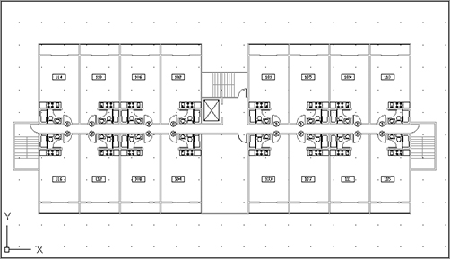
1. Open the Plan file. If you didn’t create the Plan file, you can use the 14a-plan.dwg or 14a-plan-metric.dwg file (see Figure 14-2).
Figure 14-2:The overall plan
2. If they are not already, turn off the Ceiling and Flr-pat layers to get a clear, uncluttered view of the individual unit plans.
3. Use the Wblock command (enter W↵ at the Command prompt), and write the eight units in the corners of your plan to a file called Floor1.dwg in your Documents folder (see Figure 14-3). When you select objects for the Wblock, be sure to include the S-DOOR door reference symbols and apartment number symbols for those units. Use 0,0 for the Wblock insertion base point. Also make sure the Delete Objects check box is selected in the Write Block dialog box before you click the Write Block button.
Figure 14-3:Units to be exported to the Floor1 file
4. Using Figure 14-4 as a guide, insert the Unit2.dwg file into the corners where the other eight units were previously. Metric users should use Unit2-metric.dwg. These files can be found in the Chapter 14 sample files available on the companion website. If you didn’t create the Unit2 file earlier in this chapter, use the 14a-unit2.dwg file.
Figure 14-4:Insertion information for Unit2. Metric coordinates are shown in brackets.

5. After you’ve accurately placed the corner units, use the Wblock command to write these corner units to a file called Floor2.dwg. Again, use the 0,0 coordinate as the insertion base point for the Wblock, and make sure the Delete Objects check box is selected.
6. Choose File Save As from the menu bar to turn the remaining set of unit plans into a file called Common.dwg.
You’ve just created three files: Floor1, Floor2, and Common. Each file contains unique information about the building. Next, you’ll use the Xref command to recombine these files for the different floor plans in your building.
Assembling Xrefs to Build a Drawing
You’ll now create composite files for each floor using Xrefs of only the files needed for the individual floors. You’ll use the Attach Reference option of the Xref command to insert all the files you exported from the Plan file.
Follow these steps to create a file representing the first floor:
1. Close the Common.dwg file, create a new file, and call it Xref-1.
2. Set up this file as an architectural drawing, 8½˝ 11˝ with a scale of 1⁄16˝ = 1´. The upper-right corner limits for such a drawing are 2112,1632. Metric users should set up a drawing at 1:200 scale on an A4 sheet size. Your drawing area should be 4200 cm 5940 cm. Press Z↵ A↵ to execute the Zoom All command so your drawing area is adjusted to the window.
3. Set the Ltscale value to 192. Metric users should set it to 200.
4. Type ![]() -7 to open the Reference Manager. Click the Attach Reference tool from the Reference Manager palette or type XA↵ to open the Select Reference File dialog box.
-7 to open the Reference Manager. Click the Attach Reference tool from the Reference Manager palette or type XA↵ to open the Select Reference File dialog box.
5. Locate and select the Common.dwg file.
6. In the Attach External Reference dialog box, make sure the Specify On-Screen check box in the Insertion Point group isn’t selected. Then make sure the X, Y, and Z values in the Insertion Point group are all 0 (Figure 14-5). Because the insertion points of all the files are the same (0,0), they will fit together perfectly when they’re inserted into the new files.
7. Click OK. The Common.dwg file appears in the drawing.
The drawing may appear faded. This is because AutoCAD has a feature that allows you to fade an Xref so that it is easily distinguished from other objects in your current drawing. You can change the reference-fade setting by doing the following:
1. Right-click on the drawing and select Preferences or press ![]() -, (comma). Click the Look And Feel tab. In the Transparency Controls section, locate the XRefs slider.
-, (comma). Click the Look And Feel tab. In the Transparency Controls section, locate the XRefs slider.
2. Click and drag the XRefs slider all the way to the left.
Figure 14-5:The Attach External Reference dialog box

Your Xref should now appear solid. Remember the XRefs slider; you may find that you’ll need it frequently when working with Xrefs.
Now continue to add some reference files:
1. Click Attach Reference from the Reference Manager, and then locate, select, and insert the Floor1 or Floor1-metric file.
2. Repeat step 1 to insert the Col-grid.dwg or Col-grid-metric.dwg file as an Xref. You now have the plan for the first floor.
3. Save this file.
Next, use the current file to create another file representing a different floor:
1. Choose File Save As from the menu bar to save this file as Xref-2.dwg.
2. In the Reference Manager palette, select Floor1 in the list of Xrefs.
3. Right-click and select Detach from the shortcut menu. Click Yes on the alert dialog.
5. Right-click in the blank portion of the list in the Reference Manager palette, and select Insert Reference from the shortcut menu.
6. The Select Reference File dialog will open. Locate and open Floor2.dwg.
7. In the Attach External Reference dialog box, make sure the X, Y, and Z values in the Insertion Point group are all set to 0.
8. Click OK. The Floor2 drawing appears in place of Floor1.
Now when you need to make changes to Xref-1 or Xref-2, you can edit their individual Xref files. The next time you open Xref-1 or Xref-2, the updated Xrefs will automatically appear in their most recent forms.
Locating Xref Files
If you move an Xref file after you insert it into a drawing, AutoCAD may not be able to find it later when you attempt to open the drawing. This is often indicated by visual clues in the Reference Manager. The icon next to the missing file will show with an exclamation mark, the external reference will now show a red number after it, indicating that there are missing Xref files, and the status in the Details group will indicate Not Found.
If you know that you’ll be keeping your project files in one place, you can use the Projectname system variable in conjunction with the Application Preferences dialog box to direct AutoCAD to look in a specific location for Xref files. Here’s what to do:
1. Right-click and select Preferences from the shortcut menu, press ![]() +, (comma), or enter OP↵.
+, (comma), or enter OP↵.
2. Click the Application tab, and then locate and select the Project Files Search Path option.
3. Click Add and either enter a name for your project or accept the default name of Project1.
4. Click Browse and locate and select the folder where you plan to keep your Xref files.
5. Close the Application Preferences dialog box, and then enter PROJECTNAME↵ at the Command prompt.
6. Enter the project name you used in step 3. Save your file so it remembers this setting.
Xrefs don’t need to be permanent. As you saw in the previous exercise, you can attach and detach them easily at any time. This means that if you need to get information from another file—to see how well an elevator core aligns, for example—you can temporarily attach the other file as an Xref to check alignments quickly, and then detach it when you’re finished.
Think of these composite files as final plot files that are used only for plotting and reviewing. You can then edit the smaller, more manageable Xref files. Figure 14-6 illustrates the relationship of these files.
Figure 14-6:A diagram of Xref file relationships

The combinations of Xrefs are limited only by your imagination, but you should avoid multiple Xrefs of the same file in one drawing.
Updating Blocks in Xrefs
Several advantages are associated with using Xref files. Because the Xrefs don’t become part of the drawing file’s database, the referencing files remain small. Also, because Xref files are easily updated, work can be split up among several people in a workgroup environment or on a network. For example, for your hypothetical apartment-building project, one person can be editing the Common file while another works on Floor1, and so on. The next time the composite Xref-1.dwg or Xref-2.dwg file is opened, it automatically reflects any new changes made in the Xref files. Let’s see how to set this up:
1. Save and close the Xref-2 file, and then open the Common.dwg file.
2. Update the unit plan you edited earlier in this chapter. Click the Insert tool on the Tool Sets palette. You can also type I↵.
3. In the Insert Block dialog box, click the Browse button, and then locate and select Unit.dwg. If you can’t find your Unit.dwg file, you can use 14b-unit.dwg. Click Open, and then click Insert in the Insert Block dialog box.
4. If a warning message appears, click Redefine Block.
5. At the Specify insertion point: prompt, press the Esc key.
6. Enter RE↵ to regenerate the drawing. You see the new unit plan in place of the old one (see Figure 14-7). You may also see all the dimensions and notes for each unit.
Figure 14-7:The Common file with the revised unit plan

7. If the Notes layer is on, use the Layer pop-up list to turn it off.
8. Erase all the items in the empty room across the hall from the lobby.
9. Click the Insert tool on the Tool Sets palette again, and insert the utility room on the plan (utility.dwg or utility-metric.dwg); see Figure 14-8.
Figure 14-8:The utility room inserted

10. You may have to move the utility block into place so that the walls all line up.
11. Save the Common file.
12. Open the Xref-1 file. You see the utility room and the typical units in their new form. Your drawing should look like the top image in Figure 14-9.
13. Open Xref-2. You see that the utility room and typical units are updated in this file as well. (See the bottom image in Figure 14-9.)
Figure 14-9:The Xref-1 and Xref-2 files with the units updated

Importing Named Elements from Xrefs
Chapter 5, “Keeping Track of Layers and Blocks,” discussed how layers, blocks, linetypes, and text styles—called named elements—are imported along with a file that is inserted into another file. Xref files don’t import named elements. You can, however, review their names and use a special command to import the ones you want to use in the current file.
Saving Xref Layer Settings
You can set the Visretain system variable to 1 to force AutoCAD to remember layer settings of Xref files.
AutoCAD renames named elements from Xref files by giving them the prefix of the filename from which they come. For example, the Wall layer in the Floor1 file is called Floor1|WALL in the Xref-1 file; the Toilet block is called Floor1|TOILET. You can’t draw on the layer Floor1|WALL, nor can you insert Floor1|TOILET, but you can view Xref layers in the Layers palette, and you can view Xref blocks by using the Insert Block dialog box.
Next, you’ll look at how AutoCAD identifies layers and blocks in Xref files, and you’ll get a chance to import a layer from an Xref:
1. With the Xref-1 file open, open the Layers palette by pressing ![]() +4. Notice that the names of the layers from the Xref files are all prefixed with the filename and the vertical bar (|) character.
+4. Notice that the names of the layers from the Xref files are all prefixed with the filename and the vertical bar (|) character.
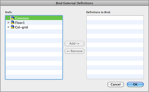
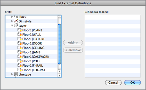
2. Enter XB↵ to open the Bind External Definitions dialog box. You see a listing of the current Xrefs. Each item shows a disclosure triangle to the left. The list box follows the Mac OS format for expandable lists (Figure 14-10).
Figure 14-10:The Bind External Definitions dialog box
3. Click the disclosure triangle next to the Floor1 Xref item. The list expands to show the types of elements available to bind (Figure 14-11).
Figure 14-11:The expanded Floor1 list

4. Click the disclosure triangle next to the Layer item. The list expands further to show the layers available for binding (Figure 14-12).
5. Locate Floor1|WALL in the list, click it, and then click the Add button. Floor1|WALL is added to the list to the right, Definitions To Bind.
Figure 14-12:The expanded Layer list
6. Click OK to bind the Floor1|WALL layer.
7. Open the Layers palette.
8. Scroll down the list and look for the Floor1|WALL layer. You won’t find it. In its place is a layer called Floor1$0$WALL.
Nesting Xrefs and Using Overlays
Xrefs can be nested. For example, if the Common.dwg file created in this chapter used the Unit.dwg file as an Xref rather than as an inserted block, you would still get the same result in the Xref-1.dwg file. That is, you would see the entire floor plan, including the unit plans, when you opened Xref-1.dwg. In this situation, Unit.dwg would be nested in the Common.dwg file, which is in turn externally referenced in the Xref-1.dwg file.
Although nested Xrefs can be helpful, take care in using Xrefs this way. For example, you might create an Xref by using the Common.dwg file in the Floor1.dwg file as a means of referencing walls and other features of the Common.dwg file. You might also reference the Common.dwg file into the Floor2.dwg file for the same reason. After you did this, however, you’d have three versions of the Common plan in the Xref-1.dwg file because each Xref would have Common.dwg attached to it. And because AutoCAD would dutifully load Common.dwg three times, Xref-1.dwg would occupy substantial computer memory, slowing your computer when you edited the Xref-1.dwg file.
To avoid this problem, use the Overlay option in the Attach External Reference dialog box. An overlaid Xref can’t be nested. For example, if you use the Overlay option when inserting the Common.dwg file into the Floor1.dwg and Floor2.dwg files, the nested Common.dwg files are ignored when you open the Xref-1.dwg file, thereby eliminating the redundant occurrence of Common.dwg. In another example, if you use the Overlay option to import the Unit.dwg file into the Common.dwg file, and then attach the Common.dwg into Xref-1.dwg as an Xref, you don’t see the Unit.dwg file in Xref-1.dwg. The nested Unit.dwg drawing is ignored.
As you can see, when you use Xbind to import a named item, such as the Floor1|WALL layer, the vertical bar (|) is replaced by two dollar signs surrounding a number, which is usually zero. (If for some reason the imported layer name Floor1$0$WALL already exists, the zero in that name is changed to 1, as in Floor1$1$WALL.) Other named items are renamed in the same way, using the $0$ replacement for the vertical bar.
You can also use the Bind External Definitions dialog box to bind multiple layers as well as other items from Xrefs attached to the current drawing. You can bind an entire Xref to a drawing, converting it to a simple block. By doing so, you have the opportunity to maintain unique layer names of the Xref being bound or to merge the Xref’s similarly named layers with those of the current file. See Chapter 7 for details.
Controlling the Xref Search Path
One problem AutoCAD users have encountered in the past is lost or broken links to an Xref. This occurs when an Xref file is moved from its original location or when you receive a set of drawings that includes Xrefs. The Xref links are broken because AutoCAD doesn’t know where to look. Since AutoCAD 2005, you have had better control over how AutoCAD looks for Xref files.
When you insert an Xref, the Attach External Reference dialog box opens, offering you options for insertion point, scale, and rotation. This dialog box also provides the Path Type option, which enables you to select a method for locating Xrefs. You can choose from three Path Type options:
Full Path Lets you specify the exact filename and path for an Xref, including the disk drive or network location. Use this option when you want AutoCAD to look in a specific location for the Xref.
Relative Path Lets you specify a file location relative to the location of the current or host drawing. This option is useful when you know you’ll maintain the folder structure of the host and Xref files when moving or exchanging these files. Note that because this is a relative path, this option is valid only for files that reside on the same local hard disk.
No Path Perhaps the most flexible option, this tells AutoCAD to use its own search criteria to find Xrefs. When No Path is selected, AutoCAD first looks in the same folder of the host drawing; then it looks in the project search path defined in the Application tab of the Application Preferences dialog box. Last, AutoCAD looks in the Support File Search Path option, also defined in the Application tab of the Application Preferences dialog box. If you plan to send your files to a client or a consultant, you may want to use this option.
In a survey of AutoCAD users, Autodesk discovered that one of the most frequently used features in AutoCAD is the Layer command. You’ll find that you turn layers on and off to display and edit the many levels of information contained in your AutoCAD files. All of the layer management tools can be found in the Format Layer Tools submenu on the menu bar, but some are also found on the Layers palette.
You can quickly revert to a previous layer setting by choosing Format Layer Tools Layer Previous. The Layer Previous tool enables you to revert to the previous layer settings without affecting other settings in AutoCAD. Note that Previous mode doesn’t restore renamed or deleted layers, nor does it remove new layers.
Changing the Layer Assignment of Objects
There are two tools that change the layer assignments of objects: the Layer Match tool and the Change To Current Layer tool.
The Layer Match tool is similar to the Match Properties tool, but it’s streamlined to operate only on layer assignments. After clicking this tool on the Layers palette, select the object or objects you want to change, press ↵, and then select an object whose layer you want to match.
The Change To Current Layer tool on the Format Layer Tools submenu on the menu bar changes an object’s layer assignment to the current layer. This tool has long existed as an AutoLISP utility, and you’ll find that you’ll get a lot of use from it.
Controlling Layer Settings through Objects
The remaining Layer tools let you make layer settings by selecting objects in the drawing. These tools are easy to use: click the tool or menu item, and then select an object.
The following list describes each tool:
Layer Isolate/Layer Unisolate Layer Isolate turns off all the layers except for the layer of the selected object. Layer Unisolate restores the layer settings to the way the drawing was set before you used Layer Isolate.
Layer Freeze Freezes the layer of the selected object.
Layer Off Turns off the layer of the selected object.
Layer Lock/Layer Unlock Locks/unlocks the layer of the selected object. A locked layer is visible but can’t be edited.
Make Object’s Layer Current Enables you to set the current layer by selecting an object that is on the desired layer.
Isolate To Current Viewport Enables you to freeze layers in all but the current viewport by selecting objects that are on the layers to be frozen. Found in the Format Layer Tools submenu on the menu bar.
Delete Deletes all objects on a layer and then deletes the layer. Found in the Format Layer Tools submenu on the menu bar.
Select Similar and Isolate Object for Easier Editing
There are a few new features that can help speed up object selection. First, let’s explore the Select Similar command.
Just as the name implies, Select Similar will select all objects in the drawing that are similar to the one currently selected. For example, if you wish to select all similar hatches on the drawing, Select Similar will be your best friend. This command can be invoked either before or after object selection. If you choose to use it before selecting objects, you can find the tool on the Tool Sets palette. The Select objects or [Settings]: prompt is displayed. Select an object, such as a line, and then press Enter. All items on the drawing that are lines and are on the same layer and color will be highlighted.
If you select an object and right-click, you’ll see the Select Similar option. Click on a line, right-click, and then click Select Similar, and all the lines that are on the selected line’s layer will be highlighted.
You can control how the Select Similar feature behaves by entering SELECTSIMILAR↵ SE↵. This opens the Select Similar Settings dialog box, which lets you set the basis for the similar selection, such as layer, color, or linetype, to name a few.

Another handy option is to isolate. If you have a set of objects, right-click, and select Isolate Isolate Objects; all but the selected objects will be made invisible. Or you can right-click and select Isolate Hide Objects to hide the selected objects. To bring back the objects that were made invisible, right-click and select Isolate End Object Isolation. If you happen to save and close a drawing that has the object isolation in effect, when you reopen the drawing, the isolated layers will be reset as if you performed the End Object Isolation command.
Singling Out Proximate Objects
You’ll sometimes need to select an object that overlaps or is very close to another object. Often in this situation you end up selecting the wrong object. To select the exact object you want, you can use the Draworder command.
You can select the overlapping object and then from the right-click menu, choose Send To Back from the Draworder flyout.
Use external references (Xrefs). You’ve seen how you can use Xrefs to quickly build variations of a floor plan that contains repetitive elements. This isn’t necessarily the only way to use Xrefs, but the basic idea of how to use Xrefs is presented in the early exercises.
Master It Try putting together another floor plan that contains nothing but the Unit2 plan.
Change Layer information. Layers is a powerful tool used in AutoCAD drawings. You can modify a layer using various properties found in the Layers palette.
Master It Modify the Ceiling layer so that it displays a very light gray line.
Select similar objects. Select Similar can select alike objects. It can be invoked from the shortcut menu when objects are selected.
Master It Select all the walls on the plan drawing and change them so that they are now set to the color magenta. Now reset them to their previous color.