
Bonus Chapter 2
Customizing Toolsets, Menus, Linetypes, and Hatch Patterns
Mastering AutoCAD for Mac
Bonus Chapter 2 accompanies Mastering AutoCAD for Mac, by George Omura and Rick Graham. Learn more about this book at www.sybex.com/go/masteringautocadmac.
AutoCAD offers a high degree of flexibility and customization, enabling you to tailor the software’s look and feel to your requirements. In this bonus chapter, you’ll see how to customize AutoCAD so that it integrates more smoothly into your workgroup and office environment.
The first part of the chapter shows how to adapt AutoCAD to fit your particular needs. You’ll learn how to customize AutoCAD by modifying its menus, and you’ll learn how to create custom macros for commands that your workgroup uses frequently.
You’ll then look at some general issues that arise when you use AutoCAD in an office. In this discussion, you may find help with problems you’ve encountered when using AutoCAD in your particular work environment. I’ll also discuss how to manage AutoCAD projects.
In this bonus chapter, you’ll learn to do the following:
- Customize the user interface
- Create macros in tools and menu items
- Understand the Diesel macro language
- Create custom linetypes
- Create hatch patterns
Customizing the User Interface
Out of the box, AutoCAD offers a generic arrangement of tools organized into toolsets and menu bar menus. But the more you use AutoCAD, the more you may find that you tend to use tools that are scattered over several toolsets or are not available by default. You’ll probably feel that your work would go more easily if you could create custom toolsets and menus. If you’re to the point of creating custom macros, you may want a way to have easy access to them.
The Customize User Interface (CUI) is a one-stop location that gives you nearly total control over toolsets and menus in AutoCAD. With the CUI, you can mold the AutoCAD interface to your liking. The main entry point to the CUI is the Customize dialog box.
The following section introduces you to the CUI by showing you how to add a tool to the Drafting toolset.
A Quick Customization Tour
The most direct way to adapt AutoCAD to your way of working is to customize a Tool Sets palette. AutoCAD offers new users an easy route to customization through the Customize dialog box. With this dialog box, you can create new toolsets, tool groups, and menus and customize tools.
To get your feet wet, try adding the Polyline Edit tool to the Drafting toolset:
1. Choose Tools Customize Interface (CUI) from the menu bar, or type CUI↵. The Customize dialog opens. You see three tabs along the top in this dialog box: Commands, Menus, and Tool Sets.
2. Click the Tool Sets tab (Figure B2.1).
Figure B2.1: The Customize dialog box

3. Click the disclosure triangle next to Drafting. You see the tool groups assigned to the Drafting toolset (Figure B2.2).
4. Click the disclosure triangle next to the Modify tool group. It expands and you can see the various tools (Figure B2.3). It is here that you are going to add the Polyline Edit command.
Figure B2.2: The tool groups within the Drafting toolset

Figure B2.3: The tools within the Modify tool group

5. On the left side of the Customize dialog, you see the Commands list. Scroll down the list until you find the Polyline Edit command.
6. Select the Polyline Edit command and drag it over to the Tool Sets list. As you drag it over, you will see a horizontal bar. This is showing you where the command will go (Figure B2.4).
Figure B2.4: Drag and drop the Polyline Edit command.

7. When the bar is at the location shown in Figure B2.4, release the mouse button to insert the tool within the Modify tool group (Figure B2.5). If you don’t have it at the exact location shown, don’t worry—we will cover that next.
Figure B2.5: The Polyline Edit tool added within the Modify tool group

For this exercise, you want the Polyline Edit command to appear under the Chamfer command. So here’s how you’ll handle that.
8. Select the Polyline Edit command and drag it up so that the horizontal bar appears below Chamfer (Figure B2.6)
Figure B2.6: Drag the Polyline Edit tool up.

9. Click OK. After a moment, you will be returned to the drawing window. Take a look at the Drafting toolset and notice that the Polyline Edit command has been added to the Modify tool group (Figure B-7).
Figure B-7:The tool is in place.

You’ve just added a tool to the Drafting toolset. You can follow the previous steps to add any command to any tool group or menu bar menu. Now, suppose you change your mind and you decide to remove Polyline Edit from the Drafting toolset. Here’s how it’s done:
1. Type CUI↵.
2. In the Tool Sets tab of the Customize dialog box, expand the Drafting toolset and then continue to expand as you did before to get to the Polyline Edit command you added earlier.
3. Select the Polyline Edit command at the bottom of the Modify tool group, and choose the Options action menu.
4. From the drop-down menu, select Delete. The Polyline Edit command is removed.
5. Click OK to close the dialog box.
Polyline Edit has been removed from the Drafting tool set. As you’ve just seen, adding tools to a tool group is a matter of clicking and dragging the appropriate item from one list to another. To remove tools, you simply select the Options action menu and choose Delete.
Before you go too much further, you may want to know a little more about the Customize dialog box and how it works. Let’s look at each tab independently to see how it’s organized.
The Tool Sets Tab
If you expand a drop-down item in the toolset, you’ll see the tools that appear in the flyouts of the tool (see Figure B2.8).
Figure B2.8: The tools in the Tool Sets tab and Open Shapes tool group and how they appear in the Tool Sets palette.

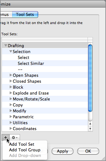
You can add new tool sets, tool groups, and drop-downs by clicking an item in the list, clicking on the + button, and then selecting the appropriate option from the shortcut menu (Figure B2.9).
Using these lists, you’ll find that it is quite easy to customize toolsets and tool groups to your liking.
Figure B2.9: Create new toolsets, tool groups, and drop-downs via the shortcut menu.
The Menus Tab
The Menus tab works similarly to the Tool Sets tab. You can edit the items in the menu bar via the Menus tab.
The difference is that there are now menus and submenus that replace the toolset, tool group, and drop-down options in the Tool Sets tab (Figure B2.10).
Figure B2.10: The tools in the Menus tab and Modify menu

Let’s add the Polyline Edit command to the menu bar. The steps will be similar to the previous exercise:
1. Type CUI↵. The Customize dialog opens.
2. Click the Menus tab.
3. Click the disclosure triangle next to the Modify menu. It expands to show submenus. It is here that you are going to add the Polyline Edit command.
4. On the left side of the Customize dialog, you see the Commands list. Scroll down the list until you find the Polyline Edit command.
5. Click the Polyline Edit command and drag it over to the Menus list. As you drag it over, you will see a horizontal bar. This is showing you where the command will go (see Figure B2.4).
6. Select the Polyline Edit command at the bottom of the Modify tool group, and choose the Options action menu.
7. From the drop-down menu, select Delete. The Polyline Edit command is removed.
Figure B2.11 shows the relationship between the tools in the menu bar and where you find them in the Customize Menus tab.
Figure B2.11: The tools in the Menus tab and File menu and how they appear on the menu bar

Inserting a Separator
In both the Tool Sets and Menus tabs, you may have noticed the lines under a group of commands. This is a separator. They are available via the Elements action menu in both cases and can be moved or deleted in the same manner as the commands on the Tool Sets and Menus tabs.
Their purpose is to visually break up tool groups (in the Tool Sets palette) and menus (on the menu bar).
The Commands Tab
The Commands tab, shown in Figure B2.12, is where you will be performing the most customization. It is divided into three areas: Commands, Properties, and Information.
The Commands Group
This is the same group you encountered when you were in the Tool Sets and Menus tabs. You’ve already seen how the Commands list contains all the commands in AutoCAD. You also saw that you can click and drag these items into in the Tool Sets and Menus lists.
The Image column shows what the tool’s icon will look like when in use in a Tool Sets palette, as shown in Figure B2.13.
The Command column shows the name of the command.
Figure B2.12: The Commands tab
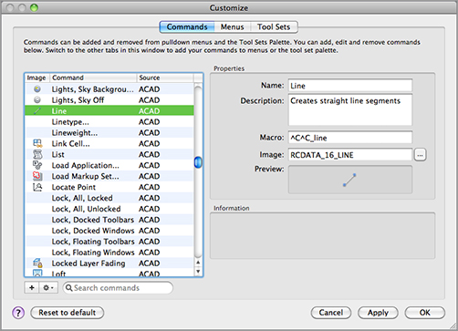
Figure B2.13: The relationship between the image in the Commands tab (left panel) and the Tool Sets palette (right panel)
The Filter Commands List
On the bottom of the Commands group, there is an input box that is quite powerful. You may recall in previous exercises, you had to search for a command to drag over to the Tool Sets or Menus lists. Using this input box, your search will be simplified. For example, if you are looking for the Polyline Edit command, rather than using the scroll bar, you can type in POL. Commands that contain the letters pol will appear. (Of course, you can also type in the entire term you are searching for.) From this filtered list, you can easily find the Polyline Edit command.
To clear the filter search and list all commands, click the X to the right of the input box.

The Properties Group
Finally, when you’re ready to do some serious customizing, you’ll work with the Properties group. You see the Properties group on the right side of the Commands tab when you select a command from the left side (Figure B2.14).
Figure B2.14: The Properties group
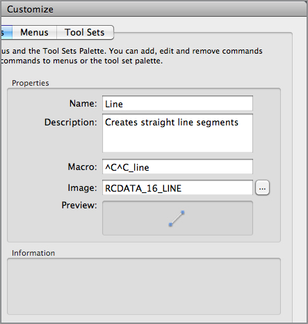
The Properties group contains the options shown in Table B2-1
Table B2-1: The Properties group options
| Name | Description |
| Name | The name the command will display on menus and in tooltips when it’s added to a toolset. |
| Description | The information here will be used in tooltips when the command is added to a toolset. |
| Macro | This will be covered in the “Creating Macros for Tools and Menus” section later this chapter. |
| Image | The image that will be displayed on the tool’s icon when it’s added to a toolset. |
| Preview | A preview of what the image will look like. |
| Information | Information about the field that has focus in the Properties group. |
Creating Your Own Toolset and Tool Groups
You can collect your most frequently used tools into a custom toolset. Now that you’ve had a chance to become familiar with the Customize dialog box, try the following exercise to create your own toolset:
1. If the Customize dialog box isn’t open, type CUI↵.
2. Click the Tool Sets tab, and at the bottom, click the + button. From the drop-down menu, choose Add Tool Set.
3. You now see a new toolset named Tool Set1. Note that the name might be different depending on how many times you have previously added a toolset.
4. Replace the name Tool Set1 by typing Mastering to give your toolset a distinct name. If you decide to change the toolset name later, click on the toolset name and then click on it again. Then type the new name. Remember that you can also move the toolset up and down the list by click-dragging it.
You now have a custom toolset, but it is empty. And it has no image associated with it. Let’s add a few tool groups.
1. Make sure you have the Mastering toolset selected. You may notice that when you click on the disclosure triangle next to the Mastering toolset, there is a panel created called Tool Group1. A toolset cannot be empty, so when a new one is created, it also creates the Tool Group1 tool group.
2. Change the name from Tool Group1 to Linework.
3. Now you will add one more tool group. Click the + button. On the drop-down menu, select Add Tool Group.
4. Rename this tool group Dimensions. Your Customize dialog box should look like Figure B2.15.
Figure B2.15: The Mastering toolset in the Customize dialog box

For now, click OK and admire your work thus far.

As you can see, the Mastering toolset isn’t very useful yet. Let’s add some tools:
1. Type CUI↵ and click the Tool Sets tab.
2. Expand the Mastering toolset and the Linework tool group. You see a separator.
3. Drag the Line and Polyline commands over to the Linework panel.
4. Click the Polyline command to highlight it.
5. Click the + icon. On the drop-down menu, select Add Drop-Down. Rename “drop-down” Arcs Drop-down.
6. Populate the Arcs drop-down as shown in Figure B2.16. Click OK.
Figure B2.16: The Arcs Drop-down list in the Mastering toolset


7. Back in the CUI, create a Dimensions drop-down under the Dimension tool group. Drag dimension commands into your Dimensions drop-down, shown in Figure B2.17.
Figure B2.17: The Dimensions Drop-down list in the Mastering toolset

If you click OK to view your work, you will notice that the Dimensions drop-down is not next to the Arcs drop-down. This is because they are in different tool groups.
Customizing Tool Sets Palette Tools
Let’s move on to more serious customization. Suppose you want to create an entirely new tool with its own functions. For example, you might want to create a set of tools that insert your favorite symbols. Or you might want to create a Tool Sets palette tool containing a set of tools that open some of the other toolbars that are normally put away.
Creating a Custom Tool
Follow these steps to create a custom tool:
1. Open the Customize dialog box, and click the Commands tab.
2. In the Commands group, click the + button. A new command called Command1 appears in the list of commands (Figure B2.18).
3. Double-click the Command1 item, and change the name by typing Door↵.
4. In the Properties group to the right, change the description by typing Insert a 36˝ door. and press the Tab key.
5. Change the Macro option to the following:
^C^C-insert door;36;;
What Is the Hyphen For?
Notice that you use a hyphen in front of the Insert command. The hyphen causes the Insert command to run in the command line instead of using a dialog box, where the macro input will not work. Many commands will run in the command line when preceded with a hyphen.
Figure B2.18: Click the + button to create a new command.

6. Switch to the Tool Sets tab and expand the Mastering toolset.
7. Click and drag the Door command from the Commands list into the Linework tool group, as shown in Figure B2.19.
Figure B2.19: The Door command added to the Mastering toolset

8. Click OK to exit and save your changes. If you look at the Mastering toolset, you see that the Door command you just added appears as a blank tool. This happens when no icon has been assigned to the tool. We will address that later in this chapter.

Using Slashes in Macros
The series of keystrokes you entered for the macro in step 5 are the same as those you would use to insert the door, with the addition of a few special characters. The semicolons are equivalent to a ↵, and the backward slash () is a special macro code that tells AutoCAD to pause the macro for user input. In this case, the pause allows you to select the insertion point for the door. For more information on the use of the backward slash, see the section “Pausing for User Input” later in this bonus chapter.
Next, try the custom tool to make sure it works:
1. Put a copy of the Door.dwg file in your Documents folder. You can find this drawing in the Bonus 2 chapter folder found at www.sybex.com/go/masteringautocadmac.
2. Move your mouse over the Door tool in Mastering toolset. You see the Door tooltip.
3. Click the Door tool. The door appears in the drawing area at the cursor. It may appear very small because initially, it’s being inserted at its default size of 1 unit.
4. Click a location to place the door, and then click a point to set the door rotation. The door appears in the drawing.
Locate Files So AutoCAD Can Find Them
A misplaced file is one of the most common problems to troubleshoot supporting an office full of AutoCAD users. AutoCAD likes to place files in a lot of different places. When it can’t find a file it needs, it will give you an error message, or worse, it just won’t work. It helps to know where AutoCAD looks for files so you can place the resources for your custom tools in the right places.
In the door example, the Door drawing used in your macro must be in the default folder, Documents, or in the AutoCAD search path before the door will be inserted.
In this example, you created a custom tool that inserts the Door block. Later in this bonus chapter, you’ll learn more about creating macros for menus and tools. But first you’ll learn how to add a custom icon for your custom tool.
Using Icons in the Customize Dialog
You have all the essential parts of the tool defined. Now you just need to assign an icon to go with your Door tool:
1. Copy the Door.bmp from the Bonus 2 chapter folder found at www.sybex.com/go/masteringautocadmac to the Documents folder.
2. Open the Customize dialog box.
3. In the Commands tab, find the Door tool you just created.
4. In the Properties group, click the ellipsis next to the Image input box. The Select An Image File dialog opens.
5. Find the previously copied Door.bmp file and click Open. You’ll see your custom icon for the Door command.
Add an Icon for the Mastering Toolset
You may have also noticed that there is no icon for the Mastering toolset. The process is basically the same as the process for adding an icon for a tool:
1. In the Customize dialog, click on the Tool Sets tab.
2. Click on the Mastering toolset and then right-click.
3. Choose Specify Tool Set Image. The Specify Tool Set Image dialog opens.

4. Click the ellipsis next to the Image input box. The Select An Image File dialog opens.
5. Navigate to the location of your icon and click Open.
You can create icons, but you have to make sure that they are no larger than 16x16 pixels.
Creating Macros for Tools and Menus
Combining existing commands into new toolsets or menus can be useful, but you’ll get even more benefit from creating your own macros. Macros are predefined sets of responses to commands that can help automate your most frequently used processes.
Early on, you saw how a macro was included in a command to insert a door. You added a special set of instructions in the Macro option of the Properties group to perform the door insertion and scale.
Let’s take a closer look at how macros are built. Start by looking at the existing Line tool and how it’s formatted.
The Macro option for the Line command starts with two ^C elements, which are equivalent to pressing the Esc key twice. This cancels any command that is currently operative. (Two cancels are issued in case you’re in a command that has two levels, such as the Edit Vertex option of the Pedit command.)

The AutoCAD Line command follows, written just as it would be entered at the Command prompt. The underscore character (_) that precedes the Line command tells AutoCAD that you’re using the English-language version of this command. This feature lets you program non-English versions of AutoCAD by using the English-language command names.
You may notice that there is no space between the second ^C and the Line command. A space in the macro would be the same as ↵. If there were a space between these two elements, ↵ would be entered between the last ^C and the Line command, causing the command sequence to misstep. Another way to indicate ↵ is by using the semicolon, as in the following example:
^C^C_Line;;
Help Make Your Macro Readable
If a macro contains multiple instances of ↵, using semicolons instead of spaces can help make your macro more readable.
In this sample macro, the Line command is issued, and then an additional ↵ is added. The effect of choosing this option is a line that continues from the last line entered into your drawing. The two semicolons following Line tell AutoCAD to type Line at the Command prompt and then issue ↵ twice; the first ↵ starts the Line command, and then the second ↵ tells AutoCAD to begin a line from the endpoint of the last line entered. (AutoCAD automatically issues a single ↵ at the end of a menu line. In this case, however, you want two instances of ↵, so they must be represented as semicolons.)
Another symbol used in the Macro option is the backslash (); it’s used when a pause is required for user input. For example, the following sample macro starts the Arc command and then pauses for your input:
^C^C_arc \_e \_d
The space between ^c^c_arc and the backslash () represents pressing ↵. The backslash indicates a pause to enable you to select the starting endpoint for the arc. The _e represents the selection of the Endpoint option under the Arc command after you’ve picked a point. A second backslash allows another point selection. Finally, the _d represents the selection of the Direction option. Figure B2.20 illustrates this. Note that if you want the last character in a menu item to be a backslash, you must follow the backslash with a semicolon.
Figure B2.20: The execution of the sample macro defined with the Arc command
Understanding the Diesel Macro Language
Diesel is one of many macro languages AutoCAD supports, and you can use it to perform simple operations and add some automation to menus. As with AutoLISP, parentheses are used to enclose program code.
In the following sections, you’ll look at the different ways to use the Diesel macro language. You’ll start by using Diesel directly from the command line. This will show you how a Diesel macro is formatted and will give you a chance to see Diesel in action. Also, you’ll see how Diesel can be used as part of a macro to test AutoCAD’s current state. Next, you’ll learn how to use Diesel with field objects to control text in your drawing.
Using Diesel in a Custom Menu Macro
You can use a Diesel expression to control the behavior of a macro:
^C^C_Blipmode;$M=$(-,1,$(getvar,Blipmode))
This macro turns Blipmode on or off depending on Blipmode’s current state. As you may recall, Blipmode is a feature that displays point selections in the drawing area as tiny crosses. These tiny crosses, or blips, don’t print and can be cleared from the screen with a redraw. They can be helpful when you need to track your point selections.
In this example, the Blipmode command is invoked, and then the $M= tells AutoCAD that a Diesel expression follows. The expression
$(-,1,$(getvar,Blipmode))
returns either 1 or a 0, which is applied to the Blipmode command to turn it either on or off. This expression shows that you can nest expressions. The most deeply nested expression is evaluated first, so AutoCAD begins by evaluating
$(getvar,Blipmode)
This returns either 1 or a 0, depending on whether Blipmode is on or off. Next, AutoCAD evaluates the next level in the expression
$(-,1,getvar_result)
in which getvar_result is either 1 or a 0. If getvar_result is 1, the expression looks like
$(-,1,1)
which returns 0. If getvar_result is 0, the expression looks like
$(-,1,0)
which returns 1. In either case, the end result is that the Blipmode command is assigned a value that is opposite of the current Blipmode setting.
You’ve just skimmed the surface of what Diesel can do. To get a more detailed description of how Diesel works, press the F-, (comma) key combination to open the AutoCAD for Mac Help website. Click the Customization Guide listing, and click the DIESEL listing that appears.
Table B2-2 shows some of the commonly used Diesel functions. Check the AutoCAD for Mac Help documentation for a more detailed list.
Table B2-2: Sample of Diesel functions

Using Diesel and Fields to Generate Text
Using Diesel expressions in a macro can be helpful to gather information or to create a more interactive interface, but what if you want the results of a Diesel expression to become part of the drawing? You can employ field objects to do just that.
For example, suppose you want to create a note that shows the scale of a drawing based on the dimension scale. Further, you want the scale in the note to be updated automatically whenever the dimension scale changes. You can add a field object and associate it with a Diesel expression that displays the dimension scale as it relates to the drawing scale. Try the following steps to see how it’s done:
1. Click the Tool Sets button and choose Annotation. In the Annotation toolset, click the Multiline Text tool on the Text tool group and select two points to indicate the text location. The Text Editor appears.
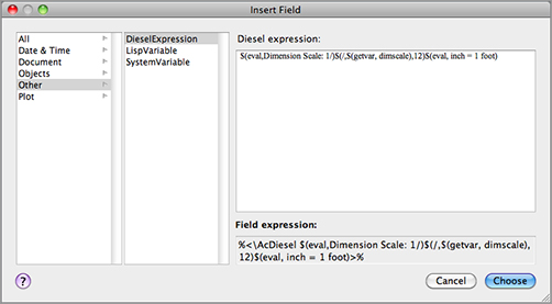
2. Right-click in the text editor, and select Insert Field to open the Insert Field dialog box.
3. In the list on the left, select Other; then, in the middle list, select DieselExpression.
4. Add the following text in the Diesel Expression input box to the right:
$(eval,Dimension Scale: 1/)$(/,$(getvar, dimscale),12)$(eval, inch = 1 foot)
5. Your screen should look like Figure B2.21. Click the Choose button in the Insert Field dialog box, and then click the Save on the Text Editor visor. The following text is displayed in the drawing:
Dimension Scale: 1/0.08333333 inch = 1 foot
Figure B2.21: Inserting a macro into a field
The resulting text may not make sense until you change the dimension scale to a value that represents a scale other than 1 to 1. Here’s how to do that:
1. Enter DIMSCALE↵ at the Command prompt.
2. At the Enter new value for DIMSCALE <1.0000>: prompt, enter 96. This is the value for a 1⁄8˝ scale drawing.
3. Type RE↵. The text changes to read
Dimension Scale: 1⁄8 inch = 1 foot
In this example, several Diesel functions were used. The beginning of the expression uses the eval operation to tell AutoCAD to display a string of text:
$(eval,Dimension Scale: 1/)
The next part tells AutoCAD to get the current value of the Dimscale system variable and divide it by 12:
$(/,$(getvar,dimscale),12)
Notice that this is a nested expression: $(getvar,dimscale) obtains the value of the Dimscale system variable, which is then divided by 12. The end of the expression adds the final part to the text:
$(eval, inch = 1 foot)
When it’s all put together, you get the text that shows the dimension scale as an architectural scale. Because it’s an AutoCAD text object, this text is part of the drawing.
As your drawing needs expand, the standard linetypes may not be adequate for your application. Fortunately, you can create your own. The following sections explain how to do so. You’ll get an in-depth view of the process of creating linetypes.
Viewing Available Linetypes
Although AutoCAD provides the linetypes most commonly used in drafting (see Figure B2.22), the dashes and dots may not be spaced the way you would like, or you may want an entirely new linetype.
Figure B2.22: The lines in this list of standard linetypes were generated with the underscore key (_) and the period (.) and are only rough representations of the actual lines.

Where Are the Linetypes Stored?
AutoCAD stores linetypes in files called acad.lin (Imperial drawings) and acadiso.lin (metric drawings), which is in ASCII format. When you create a new linetype, you add information to this file. Or, if you create a new file containing your own linetype definitions, it too will have the extension .lin at the end of its name. You can edit linetypes as described here, or you can edit them directly in these files.
To create a custom linetype, use the Linetype command. Let’s see how this handy command works:
1. Enter -LINETYPE↵.
2. At the Enter an option [?/Create/Load/Set]: prompt, enter C↵.
3. At the Enter name of linetype to create: prompt, enter Custom_CL↵ as the name of your new linetype.
4. The dialog box you see next is named Create Or Append Linetype File. You need to enter the name of the linetype file you want to create or add to. If you select the default linetype file, acad, your new linetype is added to the acad.lin file. If you choose to create a new linetype file, AutoCAD creates a new .lin file based on the filename you supply and adds your new linetype.
5. Let’s assume you want to start a new linetype file. Enter Mastering↵ in the Save As input box and click Save.
6. At the Descriptive text: prompt, enter a text description of your linetype. You can use any keyboard character as part of your description, but the actual linetype can be composed of only a series of lines, points, and blank spaces. For this exercise, enter the following, using the underscore key (_) to simulate the appearance of your line:
Custom_CL – My own center line __________ _ ____________ ↵
7. At the Enter linetype pattern (on next line): prompt, enter the following numbers, known as the linetype code (after the A that appears automatically):
1.0,-.125,.25,-.125↵
You Can Set the Default Linetype
If you use the Set option of the -Linetype command to set a new default linetype, you’ll get that linetype no matter what layer you’re on.
8. At the New linetype definition saved to file. Enter an option [?/Create/Load/Set]: prompt, press ↵ to exit the -Linetype command.
You may be wondering what purpose the A serves at the beginning of the linetype code. A linetype is composed of a series of line segments and points. The A, which is supplied by AutoCAD automatically, is a code that forces the linetype to start and end on a line segment rather than on a blank space in the series of lines. At times, AutoCAD stretches the last line segment to force this condition, as shown in Figure B2.23.
Figure B2.23: AutoCAD stretches the beginning and the end of the line as necessary.
Remember, after you’ve created a linetype, you must load it in order to use it, as discussed in Chapter 5, “Keeping Track of Layers and Blocks.”
Add Linetypes Directly to the acad.lin File
You can also open the acad.lin or another LIN file in any Mac OS text editor and add the descriptive text and linetype code directly to the end of the file.
Understanding the Linetype Code
In step 7 of the previous exercise, you entered a series of numbers separated by commas. This is the linetype code, representing the lengths of the components that make up the linetype. The separate elements of the linetype code are as follows:
- The 1.0 following the A is the length of the first part of the line. (The A that begins the linetype definition is a code that is applied to all linetypes.)
- The first -.125 is the gap, or broken part of the line. The minus sign tells AutoCAD that the line is not to be drawn for the specified length, which is 0.125 units in this example.
- Next comes the positive value 0.25. This tells AutoCAD to draw a line segment 0.25 units long after the gap of the line.
- The last negative value, -.125, again tells AutoCAD to skip drawing the line for the distance of 0.125 units.
This series of numbers represents the one segment that is repeated to form the line shown in Figure B2.24. You can also create a complex linetype that looks like a random broken line, as in Figure B2.25.
Figure B2.24: Linetype description with printed line

Figure B2.25: Random broken line
Line-Segment Lengths and Scale
The values you enter for the line-segment lengths are multiplied by the Ltscale factor, so be sure to enter values for the printed lengths.
As mentioned earlier, you can also create linetypes outside of AutoCAD by using a text editor. The standard acad.lin file looks like Figure B2.22 with the addition of the code used by AutoCAD to determine the line-segment lengths.
Normally, to use a linetype you’ve created, you have to load it through either the Properties Inspector palette or the Linetype Manager dialog box. If you use one of your own linetypes frequently, you may want to create a macro so it will be available as an option on a menu or toolset.
Creating Complex Linetypes
A complex linetype is one that incorporates text or special graphics. For example, if you want to show an underground gas line in a site plan, you normally show a line with the intermittent word GAS, as in Figure B2.26. Fences are often shown with an intermittent circle, square, or X.
Figure B2.26: Samples of complex linetypes
For the graphics needed to compose complex linetypes, use any of the symbols in the AutoCAD font files discussed in Chapter 9, “Adding Text to Drawings.” Create a text style by using these symbol fonts, and then specify the appropriate symbol by using its corresponding letter in the linetype description.
To create a linetype that includes text, use the same linetype code described earlier, with the addition of the necessary font file information in brackets. For example, say you want to create the linetype for the underground gas line mentioned previously by using just the letter G. You add the following to your acad.lin or acadiso.lin file:
*Gas_line,-G-G-G-
A,1.0,-0.25,["G",STANDARD,S=.2,R=0,X=-.1,Y=-.1],-0.25
The first line serves as a description for anyone looking at this linetype code. The next line is the code itself.
The information in the square brackets describes the characteristics of the text. The actual text that you want to appear in the line is surrounded by quotation marks. Next are the text style, scale, rotation angle, X displacement, and Y displacement.
Edit the Acad.lin File to Create Complex Linetypes
You can’t use the -Linetype command to define complex linetypes. Instead, you must open the acad.lin file by using a text editor and add the linetype information to the end of the file. Make sure you don’t duplicate the name of an existing linetype.
You can substitute A for the rotation angle (the R or U value), as in the following example:
A,1.0,-0.25,["G",standard,S=.2,A=0,X=-.1,Y=-.1],-0.25
This has the effect of keeping the text at the same angle regardless of the line’s direction. Notice that in this sample, the X and Y values are -.1; this will center the Gs on the line. The scale value of .2 will cause the text to be 0.2 units high, so .1 is half the height.
In addition to fonts, you can specify shapes for linetype definitions. Instead of letters, shapes display symbols. Shapes are stored not as drawings but as definition files, similar to text font files. Shape files have the same .shx filename extension as font files and are also defined similarly. Figure B2.27 shows some symbols from sample shape files that are included with the program. The names of the files are shown at the top of each column.
Figure B2.27: Samples of shapes

To use a shape in a linetype code, you use the same format as shown previously for text. However, instead of using a letter and style name, you use the shape name and the shape filename, as in the following example:
*Capline, ====
A,1.0,-0.25,[CAP,ES.SHX,S=.5,R=0,X=-.1,Y=-.1],-0.25
This example uses the CAP symbol from the Es.shx shape file. The symbol is scaled to 0.5 units with 0 rotation and an X and Y displacement of –0.1.
Here is an example that uses the arrow shape:
*Arrowline, >
A,1.0,-0.25,[ARROW,ES.SHX,S=.5,R=90,X=-.1,Y=-.1],-0.25
Just as with the Capline example, the ARROW symbol in this example is scaled to 0.5 units with 0 rotation and an X and Y displacement of -0.1. Figure B2.28 shows what the Arrowline linetype looks like when used with a spline.
Figure B2.28: The Arrowline linetype used with a spline

In this example, the Ltype generation option is turned on or the polyline (see Chapter 17, “Drawing Curves,” for more on the Ltype generation option). Note that the arrow from the Es.shx sample shape file, which is loaded with AutoCAD, is used for the arrow in this linetype.
AutoCAD provides several predefined hatch patterns you can choose from, but you can also create your own. This section demonstrates the basic elements of pattern definition.
Unlike linetypes, hatch patterns can’t be created while you’re in an AutoCAD file. The pattern definitions are contained in an external file named acad.pat or acadiso.pat. You can open and edit this file with a text editor that can handle ASCII files. Here is one hatch pattern definition from that file:
*SQUARE,Small aligned squares
0, 0,0, 0,.125, .125,-.125
90, 0,0, 0,.125, .125,-.125
You can see some similarities between pattern descriptions and linetype descriptions. They both start with a line of descriptive text and then give numeric values defining the pattern. However, the numbers in pattern descriptions have a different meaning. This example shows two lines of numerical information. Each line represents a line in the pattern. The first line determines the horizontal line component of the pattern, and the second line represents the vertical component. A pattern is made up of line groups. A line group is like a linetype that is arrayed a specified distance to fill the area to be hatched. A line group is defined by a line of code, much as a linetype is defined. In the square pattern, for instance, two lines—one horizontal and one vertical—are used. Each of these lines is duplicated in a fashion that makes the lines appear as boxes when they’re combined. Figure B2.29 illustrates this point.
Figure B2.29: The individual and combined line groups
Look at the first line in the definition:
0, 0,0, 0,.125, .125,-.125
This example shows a series of numbers separated by commas. It represents one line group. It contains four sets of information, separated by blank spaces:
- The first component is the 0 at the beginning. This value indicates the angle of the line group, as determined by the line’s orientation. In this case, it’s 0 for a horizontal line that runs from left to right.
- The next component is the origin of the line group, 0,0. This doesn’t mean the line begins at the drawing origin (see Figure B2.30). It gives you a reference point to determine the location of other line groups involved in generating the pattern.
Figure B2.30: The origin of the patterns

- The next component is 0,.125. This determines the distance and direction for arraying the line, as illustrated in Figure B2.31. This value is like a relative coordinate indicating X and Y distances for a rectangular array. It isn’t based on the drawing coordinates, but on a coordinate system relative to the orientation of the line. For a line oriented at a 0° angle, the code 0,.125 indicates a precisely vertical direction. For a line oriented at a 45° angle, the code 0,.125 represents a 135° direction. In this example, the duplication occurs 90° in relation to the line group because the X value is 0. Figure B2.32 illustrates this point.
- The last component is the description of the line pattern. This value is equivalent to the value given when you create a linetype. Positive values are line segments, and negative values are blank segments. This part of the line group definition works exactly as in the linetype definitions you studied in the previous section.
This system of defining hatch patterns may seem somewhat limiting, but you can do a lot with it. Autodesk managed to come up with 69 patterns—and that is only scratching the surface.
Figure B2.31: The distance and direction of duplication
Figure B2.32: How the direction of the line group copy is determined
Adding Thick Lines to Linetypes
If you want to include thick lines in your hatch patterns, you have to build up line widths with multiple linetype definitions.
Customize the user interface. With the Customize dialog box, you can add or change menus and tools. Armed with the knowledge of how to do this, you can modify your menus and tools to conform with company standards
Master It Where do you customize the Tool Sets palette?
Create macros in tools and menus. A macro is a set of instructions that performs more complex operations than single commands. Macros are often built on commands with additional predefined responses to help speed data input.
Master It What does the ^C do in a macro?
Edit command aliases. Command aliases can help improve your speed when drawing in AutoCAD. They can reduce several clicks of the mouse to a simple keystroke. AutoCAD lets you create custom shortcuts for your favorite commands.
Master It What is the command alias for Copy?
Understand the Diesel macro language. If you’re adventurous, you may want to try your hand at creating more-complex macros. The Diesel macro language is an easy introduction to AutoCAD macro customization and is most useful in controlling the behavior in macros.
Master It What does the expression $(getvar, blipmode) do?
Create custom linetypes. AutoCAD offers a number of noncontinuous linetypes, and you may find them adequate for most of your work. But every now and then, you may need a specific linetype that isn’t available. Creating custom linetypes is easy once you understand the process.
Master It What is the purpose of a negative value in the linetype code?
Create hatch patterns. Like linetypes, the hatch patterns provided by AutoCAD will probably fill most of your needs. But every now and then, you may need to produce a specific pattern.
Master It How are a hatch pattern code and a linetype code similar?
Master It Solutions
Customize the user interface. With the Customize dialog box, you can add or change menus and tools. Armed with the knowledge of how to do this, you can modify your menus and tools to conform with company standards
Master It Where do you customize the Tool Sets palette?
Solution On the Tool Sets tab in the Customize dialog.
Create macros in tools and menus. A macro is a set of instructions that performs more complex operations than single commands. Macros are often built on commands with additional predefined responses to help speed data input.
Master It What does the ^C do in a macro?
Solution ^C is equivalent to pressing the Esc key.
Edit command aliases. Command aliases can help improve your speed when drawing in AutoCAD. They can reduce several clicks of the mouse to a simple keystroke. AutoCAD lets you create custom shortcuts for your favorite commands.
Master It What is the command alias for Copy?
Solution CO or CP↵.
Understand the Diesel macro language. If you’re adventurous, you may want to try your hand at creating more-complex macros. The Diesel macro language is an easy introduction to AutoCAD macro customization and is most useful in controlling the behavior in macros.
Master It What does the expression $(getvar, blipmode) do?
Solution It returns 1 or 0 depending on the current state of the Blipmode system variable.
Create custom linetypes. AutoCAD offers a number of noncontinuous linetypes, and you may find them adequate for most of your work. But every now and then, you may need a specific linetype that isn’t available. Creating custom linetypes is easy once you understand the process.
Master It What is the purpose of a negative value in the linetype code?
Solution A gap or break in the line.
Create hatch patterns. Like linetypes, the hatch patterns provided by AutoCAD will probably fill most of your needs. But every now and then, you may need to produce a specific pattern.
Master It How are a hatch pattern code and a linetype code similar?
Solution They both use numeric values to describe lines.