
Chapter 18
Getting and Exchanging Data from Drawings
AutoCAD drawings contain a wealth of data—graphic information such as distances and angles between objects as well as precise areas and the properties of objects. However, as you become more experienced with AutoCAD, you’ll also need data of a different nature. For example, as you begin to work in groups, the various settings in a drawing become important. You’ll need statistics on the amount of time you spend on a drawing when you’re billing computer time. As your projects become more complex, file maintenance requires a greater degree of attention. To take full advantage of AutoCAD, you’ll want to exchange information about your drawing with other people and other programs.
In this chapter, you’ll explore the ways in which all types of data can be extracted from AutoCAD and made available to you, your coworkers, and other programs. First you’ll learn how to obtain specific data about your drawings. Then you’ll look at ways to exchange data with other programs—such as word processors, desktop-publishing software, and even other CAD programs.
In this chapter, you’ll learn to do the following:
- Find the area of closed boundaries
- Get general information
- Use the DXF file format to exchange CAD data with other programs
- Use AutoCAD drawings in page-layout programs
Finding the Area of Closed Boundaries
One of the most frequently sought pieces of data you can extract from an AutoCAD drawing is the area of a closed boundary. In architecture, you want to find the area of a room or the footprint of a building. In civil engineering, you want to determine the area covered by the boundary of a property line or the area of cut for a roadway. In the following sections, you’ll learn how to use AutoCAD to obtain exact area information from your drawings.
Finding the Area of an Object
In this section, you’ll practice determining the areas of regular objects. You’ll start by finding the area of a simple rectangular shape, and then you’ll look at methods for finding the area of more complex shapes that include curves.
First you’ll determine the square-foot area of the living room and entry of your studio unit plan:
1. Start AutoCAD. Open the Unit file you created in Chapter 6, “Editing and Reusing Data To Work Efficiently,” or use the 18a-unit.dwg file.
2. Zoom in to the living room and entry area so you have a view similar to Figure 18-1.
Figure 18-1:Selecting the points to determine the area of the living room and entry

3. Choose Tools Inquiry Area from the menu bar, or type MEA↵ AR↵ at the Command prompt. This starts the Measuregeom command.
4. Using the Endpoint osnap, start with the lower-left corner of the living room and select the points shown in Figure 18-1. You’re indicating the boundary. Notice that as you click points, the area being calculated is indicated in green.
5. When you’ve come full circle to the eighth point shown in Figure 18-1, press ↵. You get the following message:
Area = 39570.00 square in. (274.7917 square ft), Perimeter = 76'-0"
6. Type X↵ to exit the Measuregeom command.
The number of points you can pick to define an area is limitless, so you can obtain the areas of complex shapes. Use the Blipmode feature to keep track of the points you select so you know when you come to the beginning of the point selections. Blipmode places tiny Xs, or blips, on the screen each time you click a point. These blips are just visual aids and can be removed with a redraw or regen of the screen.
Find the Coordinate of a Point or a Distance in a Drawing
To find absolute coordinates in a drawing, use the ID command. Choose Tools Inquiry ID Point, or type ID↵. At the Specify point: prompt, use the Osnap overrides to pick a point; its X, Y, and Z coordinates are displayed on the Command prompt.
To find the distance between two points, choose Distance from the Inquiry submenu on the Tools menu, or type MEA↵ D↵, and then click two points. AutoCAD will display the distance in the drawing as Delta X, Delta Y, and Delta Z coordinates and as a direct distance between the selected points. The distance is also displayed in the Command prompt. You can also type Dist↵ and pick two points to get a simplified distance measurement.
Using Hatch Patterns to Find Areas
Hatch patterns are used primarily to add graphics to your drawing, but they can also serve as a means for finding areas. You can use any hatch pattern you want because you’re interested in only the area it reports back to you. You can also set up a special layer devoted to area calculations and then use this layer to add the hatch patterns for calculating areas. That way, you can turn off the hatch patterns so they don’t plot, or you can turn off the Plot setting for that layer to ensure that it doesn’t appear in your final output.
To practice using hatch patterns to find an area, do the following:
1. Set the current layer to Floor.
2. Turn off the Door and Fixture layers. Also make sure the Ceiling layer is turned on. You want the hatch pattern to follow the interior wall outline, so you need to turn off any objects that will affect the outline, such as the door and kitchen.
3. Click Hatch on the Tool Sets palette. You can also choose Draw Hatch or type H↵ to open the Hatch And Gradient dialog box.
Measuring Boundaries That Have Gaps
If the area you’re trying to measure has gaps, set the Gap Tolerance setting in the Hatch And Gradient dialog box to a value higher than the size of the gaps. If you don’t see the Gap Tolerance setting, click the disclosure triangle in the lower-right corner of the Hatch And Gradient dialog box.
4. Click the Add: Pick Points tool. The Hatch And Gradient dialog box temporarily closes to allow you to select points in your drawing.
5. At the Pick internal point or [Select objects/remove Boundaries]: prompt, click in the interior of the unit plan. The outline of the interior is highlighted.
6. Press ↵ to return to the Hatch And Gradient dialog box, and click Preview (see Figure 18-2).
7. Right-click to complete the hatch.
8. Choose Tools Inquiry Area and press ↵, or type MEA↵ AR↵ O↵ at the Command prompt.
9. Click the hatch pattern you just created. Again, you get the following message:
Total area = 39570.00 square in. (274.7917 square ft), Perimeter = 76'-0"
10. Press X↵ to exit the command.
Figure 18-2:After you click a point on the interior of the plan to place a hatch pattern, an outline of the area is highlighted by a dotted line, and a preview of the hatch appears.

If you need to recall the last area calculation value you received, enter 'SETVAR↵ AREA↵. The area is displayed in the Command Line palette. Enter 'PERIMETER↵ to get the last perimeter calculated.
The Hatch command creates a hatch pattern that conforms to the boundary of an area. This feature, combined with the ability of the Measuregeom command to find the area of a hatch pattern, makes short work of area calculations. Another advantage of using hatch patterns is that, by default, they avoid islands within the boundary of the area you’re trying to find.
The area of a hatch pattern is also reported by the Properties Inspector palette. Select the hatch pattern whose area you want to find and then right-click and select Properties. Scroll down to the bottom of the Geometry group and you’ll see the Area listing for the hatch pattern you selected. You can select more than one hatch pattern and find the cumulative area of the selected hatch patterns in the Properties Inspector palette.
Adding and Subtracting Areas with the Area Command
Hatch patterns work extremely well for finding areas, but if you find that for some reason you can’t use hatch patterns, you have another alternative. You can use a command called Boundary to generate a polyline outline of an enclosed boundary and then obtain the area of the outline using the Measuregeom command options (the Distance, Angle, Area, Radius, Volume options in the Tools Inquiry submenu on the menu bar). If islands are present within the boundary, you have to use the Subtract feature of the Measuregeom command to remove the area of the island from the overall boundary area.
By using the Add and Subtract options of the Measuregeom command, you can maintain a running total of several separate areas being calculated. This gives you flexibility in finding areas of complex shapes. This section guides you through the use of these options.
For the following exercise, you’ll use a flange shape that contains circles (Figure 18-3). This shape is composed of simple arcs, lines, and circles. Use these steps to see how you can keep a running tally of areas:
Figure 18-3:A flange to a mechanical device

1. Exit the Unit.dwg file, and open the file Flange.dwg (see Figure 18-3). Don’t bother to save changes in the Unit.dwg file.
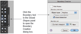
2. Click the Boundary tool from the expanded Closed Shapes panel in the Tool Sets palette. You can also choose Draw Boundary from the menu bar or type BO↵ to open the Boundary Creation dialog box (Figure 18-4).
Figure 18-4:The Boundary Creation dialog
3. Click Pick Points.
4. Click in the interior of the flange shape. The entire shape is highlighted, including the circle islands.
5. Press ↵. You now have a polyline outline of the shape and the circles, although it won’t be obvious that polylines have been created because they’re drawn over the boundary objects.
6. Continue by using the Measuregeom command’s Add and Subtract options. Choose Tools Inquiry Area from the menu bar.
7. Type A↵ to enter Add area mode, and then type O↵ to select an object.
8. Click a vertical edge of the flange outline. You see the selected area highlighted in green, and the following message appears in the Command Line palette:
Area = 27.7080, Perimeter = 30.8496
Total area = 27.7080
9. Press ↵ to exit Add area mode.
10. Type S↵ to enter Subtract area mode, and then type O↵ to select an object.
11. Click one of the circles. You see the following message:
Total area = 0.6070, Circumference = 2.7618
Total area = 27.1010
This shows you the area and perimeter of the selected object and a running count of the total area of the flange outline minus the circle. You also see the area of the subtracted circle change to a different color so you can differentiate between the calculated area and the subtracted area.
12. Click the other circle. You see the following message:
Total area = 0.6070, Perimeter = 2.7618
Total area = 26.4940
Again, you see a listing of the area and perimeter of the selected object along with a running count of the total area, which now shows a value of 26.4940. This last value is the true area of the flange.
13. Press ↵ and type X↵ X↵ to exit the Measuregeom command. You can also press the Esc key to exit the command.
In this exercise, you first selected the main object outline and then subtracted the island objects. You don’t have to follow this order; you can start by subtracting areas to get negative area values and then add other areas to come up with a total. You can also alternate between Add and Subtract modes, in case you forget to add or subtract areas.
You may have noticed that the Area option of the Measuregeom Command prompt offered Specify first corner point or [Object/Add area/Subtract area/eXit]: as the default option for both the Add and Subtract area modes. Instead of using the Object option to pick the circles, you can start selecting points to indicate a rectangular area, as you did in the first exercise in this chapter.
Whenever you press ↵ while selecting points for an area calculation, AutoCAD automatically connects the first and last points and returns the calculated area. If you’re in Add or Subtract mode, you can then continue to select points, but the additional areas are calculated from the next point you pick.
As you can see from these exercises, it’s simpler to outline an area first with a polyline wherever possible and then use the Object option to add and subtract area values of polylines.
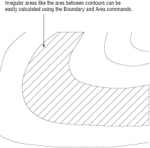
In this example, you obtained the area of a mechanical object. However, the same process works for any type of area you want to calculate. It can be the area of a piece of property on a topographical map or the area of a floor plan. For example, you can use the Object option to find an irregular shape such as the one shown in Figure 18-5, as long as it’s a closed polyline.
Figure 18-5:The site plan with an area to be calculated
When issued through the keyboard as MEA↵, the Measuregeom command offers a number of other options for measuring your drawing. The options appear in the Command Line palette as [Distance/Radius/Angle/ARea/Volume/]<Distance> or at the cursor as a Dynamic Input option. These options are automatically selected when you click the related tool from the Inquiry submenu of the Tools menu on the menu bar. Remember that to use an option, you type the capitalized letter or letters of the option shown in the list. Table 18-1 gives you descriptions of the options and how they are used.
Table 18-1: The Measuregeom command options
| Option | Use |
| Distance | Returns the distance between two points. Type D↵ and select two points. You can also measure cumulative distances by typing M↵ after selecting the first point. |
| Radius | Returns the radius of an arc or circle. Type R↵ and select an arc or circle. |
| Angle | Returns the angle of an arc or the angle between two lines. Type A↵ and select the arc or two nonparallel lines. |
| Area | Returns the area of a set of points or boundary. Type AR↵ to use this option. See previous exercises for instruction on the use of this option. |
| Volume | Returns the 3D volume based on an area times height. |
| Exit | Exits the current option. You can also press the Esc key. |
Recording Area Data in a Drawing File
In most architectural projects, area calculations are an important part of the drawing process. As an aid in recoding area calculations, it’s a good idea to create a block that contains attributes for the room number, the room area, and the date when the room area was last measured. You can then make the area and date attributes invisible so only the room number appears. The block with the attribute is then inserted into every room. Once the area of the room is discovered, it can be added to the block attribute with the Ddatte command. Such a block can be used with any drawing in which area data needs to be gathered and stored. See Chapter 12 for more on attributes. You can also use the Field object type to automatically display the area of a polyline as a text object. See Chapter 10, “Using Fields and Tables,” for more on fields.
So far in this book, you’ve seen how to get data about the geometry of your drawings. AutoCAD also includes a set of tools that you can use to access the general state of your drawings. You can gather information about the status of current settings in a file or the time at which a drawing was created and last edited.
In the following sections, you’ll practice extracting this type of information from your drawing, using the tools found in Tools Inquiry on the menu bar.
Determining the Drawing’s Status
When you work with a group of people on a large project, keeping track of a drawing’s setup becomes crucial. You can use the Status command to obtain general information about the drawing you’re working on, such as the base point and current mode settings. The Status command is especially helpful when you’re editing a drawing someone else has worked on because you may want to identify and change settings for your own style of working. Choose Tools Inquiry Status from the menu bar to display a list like the one shown in Figure 18-6.
Figure 18-6:The Command Line palette expanded to show the results from the Status command

Use the Status Command to Get Your Bearings
If you have problems editing a file created by someone else, the difficulty can often be attributed to a setting you aren’t used to working with. If AutoCAD is acting in an unusual way, use the Status command to get a quick glimpse of the file settings before you start calling for help.
Table 18-2 gives a brief description of each item on the Status screen. Note that some of the items you see on the screen will vary from what is shown here, but the information applies to virtually all situations except where noted.
Table 18-2: Items on the Status screen
| Item | Meaning |
| Number Objects In | The number of entities or objects in the drawing. |
| Model Space Limits Are | The coordinates of the Model Space limits. Also indicates whether limits are turned off or on. (See Chapter 3, “Setting Up and Using AutoCAD’s Drafting Tools,” for more details on limits.) |
| Model Space Uses | The area the drawing occupies; equivalent to the extents of the drawing. |
| **Over | If present, means that part of the drawing is outside the limit boundary. |
| Display Shows | The area covered by the current view. |
| Insertion Base Is, Snap Resolution Is, and Grid Spacing Is | The current default values for these mode settings. |
| Current Space | Model Space or Paper Space. |
| Current Layout | The current layout name. |
| Current Layer | The current layer. |
| Current Color | The color assigned to new objects. |
| Current Linetype | The linetype assigned to new objects. |
| Current Material | The material assigned to new objects. |
| Current Lineweight | The current default Lineweight setting. |
| Current Elevation/Thickness | The current default Z coordinate for new objects, plus the default thickness of objects. These are both 3D-related settings. (See Chapter 19, “Creating 3D Drawings,” for details.) |
| Fill, Grid, Ortho, Qtext, Snap, and Tablet | The status of these options. |
| Object Snap Modes | The current active Osnap setting. |
When you’re in Paper Space, the Status command displays information regarding the Paper Space limits. See Chapter 15, “Laying Out Your Printer Output,” for more on Model Space and Paper Space.
In addition to being useful in understanding a drawing file, the Status command is an invaluable tool for troubleshooting. Frequently, a technical-support person can isolate problems by using the information provided by the Status command.
Keeping Track of Time
The Time command enables you to keep track of the time spent on a drawing for billing or analysis purposes. You can also use the Time command to check the current time and find out when the drawing was created and most recently edited. Because the AutoCAD timer uses your computer’s time, be sure the time is set correctly on your Mac.
To access the Time command, enter TIME↵ at the Command prompt. You get a message like the one in Figure 18-7.
Figure 18-7:The Time screen in the Command Line palette
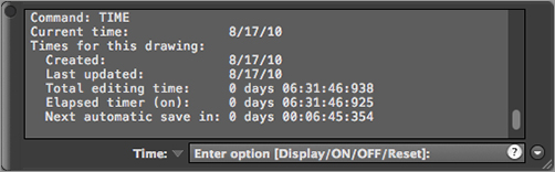
The first four lines of this message tell you the current date and time, the date and time the drawing was created, and the last time the drawing was saved.
The fifth line shows the total time spent on the drawing from the point at which the file was opened. This elapsed timer lets you time a particular activity, such as changing the width of all the walls in a floor plan or redesigning a piece of machinery. The last line tells you when the next automatic save will be.
You can turn the elapsed timer on or off or reset it by entering ON, OFF, or RESET at the Command prompt shown at the bottom of the message. Or press ↵ to exit the Time command.
Getting Information from System Variables
If you’ve been working through this book’s ongoing studio-apartment-building tutorial, you’ll have noticed that I’ve occasionally mentioned a system variable in conjunction with a command. You can check the status or change the setting of any system variable while you’re in the middle of another command. To do this, you type an apostrophe (') followed by the name of the system variable at the Command prompt.
For example, if you start to draw a line and suddenly decide you need to restrict your cursor movement to 45°, you can do the following:
1. At the Specify next point or [Undo]: prompt, enter 'SNAPANG↵.
2. At the >>Enter new value for SNAPANG <0>: prompt, enter a new cursor angle. You’re returned to the Line command with the cursor in its new orientation.
You can also recall information such as the last area or distance calculated by AutoCAD. Type SETVAR↵ AREA↵ to read the last area calculation. The Setvar command also lets you list all the system variables and their status as well as access each system variable individually by entering 'SETVAR↵ ?↵. You can then indicate which variables to list using wildcard characters such as the asterisk or question mark. For example, you can enter g* to list all the system variables that start with the letter G.
Many system variables give you direct access to detailed information about your drawing. They also let you fine-tune your drawing and editing activities. In Appendix C, “Hardware and Software Tips,” hosted on the book’s accompanying website, you’ll find all the information you need to familiarize yourself with the system variables. Don’t feel that you have to memorize them all at once; just be aware that they’re available.
Keeping a Log of Your Activity
At times, you may find it helpful to keep a log of your activity in an AutoCAD session. A log is a text file containing a record of your activities. It can also contain notes to yourself or others about how a drawing is set up. Such a log can help you determine how frequently you use a particular command, or it can help you construct a macro for a commonly used sequence of commands.
The following exercise demonstrates how to save and view a detailed record of an AutoCAD session by using the Log feature:
1. Enter LOGFILEON↵ to turn on the Log feature.
2. Type Status↵ at the Command prompt.
3. Enter LOGFILEOFF↵ to turn off the Log feature.
4. Start a text editor.
5. With the text editor, open the log file whose name starts with Flange in the folder listed here:
/Users/user name/Library/Application Support/
Autodesk/local/AutoCAD Mac/R18.1/ENU/
This file stores the text data from the Command prompt whenever the Log File option is turned on. You must turn off the Log File option before you can view this file. Note that this location is usually a hidden one. See “Finding Hidden Folders That Contain AutoCAD Files” in Appendix B (on the book’s website), “Installing and Setting Up AutoCAD for Mac,” for more information.
As you can see in step 5, the log file is given the name of the drawing file from which the log is derived, with some additional numeric values. Because the Flange log file is a standard text file, you can easily send it to other members of your workgroup or print it for a permanent record.
Finding the Log File
If you can’t find the log file for the current drawing, you can enter LOGFILENAME↵ at the Command prompt and AutoCAD will display the filename, including the full path. If you want to change the default location for the log file, open the Application Preferences dialog box and click the Application tab. Click the plus sign to the left of the Log File Location option in the list box. A listing appears showing you where the drawing log file is stored. You can then modify this setting to indicate a new location.
Capturing and Saving Text Data from the Command Line Palette
If you’re working in groups, it’s often helpful to have a record of the status, editing time, and system variables for particular files readily available to other group members. It’s also convenient to keep records of block and layer information so you can see whether a specific block is included in a drawing or what layers are normally on or off.
You can use the Clipboard to capture and save such data from the Command Line palette. The following steps show you how it’s done:
1. Move the arrow cursor to the Command prompt at the bottom of the Command Line palette.
2. Right-click and choose Copy History from the shortcut menu to copy the contents of the Command Line palette to the Clipboard.
If you want to copy only a portion of the Command Line palette to the Clipboard, perform the following steps:
1. Using the I-beam text cursor, highlight the text you want to copy from the Command Line palette to the Clipboard.
2. Right-click and choose Copy from the shortcut menu. Or you can type ![]() -C. The highlighted text is copied to the Clipboard.
-C. The highlighted text is copied to the Clipboard.
3. Open a text-editing application, and paste the information.
You may notice four other options on the shortcut menu: Recent Commands, Paste, Paste To Command Line, and Preferences. The most recent commands are listed at the top of the shortcut menu, while additional commands are listed in the More Commands submenu. For most activities, you’ll use a handful of commands repeatedly; the Recent Commands section can save you time by giving you a shortcut to those commands you use the most. The Paste options paste the first line of the contents of the Clipboard into the command line or input box of a dialog box. This can be useful for entering repetitive text or for storing and retrieving a frequently used command. Choosing Preferences opens the Application Preferences dialog box.
Items copied to the Clipboard from the Command Line palette can be pasted into dialog box input boxes. This can be a quick way to transfer layers, linetypes, or other named items from the Command Line palette into a dialog box. You can even paste text into the drawing area.
Recovering Corrupted Files
No system is perfect. Eventually, you’ll encounter a file that is corrupted in some way. Two AutoCAD commands can frequently salvage a corrupted file:
Audit Enables you to check a file that you can open but suspect has some problem. Audit checks the currently opened file for errors and displays the results in the Command Line palette.
Recover Enables you to open a file that is so badly corrupted that AutoCAD is unable to open it in a normal way. A Select File dialog box appears in which you select a file for recovery. After you select a file, it’s opened and checked for errors.
You can access these by entering them at the Command prompt. More often than not, these commands will do the job, although they aren’t a panacea for all file-corruption problems. In the event that you can’t recover a file even with these tools, make sure your computer is running smoothly and that other systems aren’t faulty.
Using the DXF File Format to Exchange CAD Data with Other Programs
AutoCAD offers many ways to share data with other programs. Perhaps the most common type of data exchange is to share drawing data with other CAD programs. In the following sections, you’ll see how to export and import CAD drawings using the DXF file format.
A Drawing Interchange Format (DXF) file is a plain-text file that contains all the information needed to reconstruct a drawing. It’s often used to exchange drawings created with other programs. Many CAD and technical drawing programs, including some 3D perspective programs, can generate or read files in DXF format. You might want to use a 3D program to view your drawing in a perspective view, or you might have a consultant who uses a different CAD program that accepts DXF files.
Be aware that not all programs that read DXF files accept all the data stored therein. Many programs that claim to read DXF files throw away much of the DXF files’ information. Attributes are perhaps the most commonly ignored objects, followed by many of the 3D objects, such as meshes and 3D faces.
Exporting and Importing DXF Files
To export your current drawing as a DXF file, follow these steps:
1. Choose File Save As from the menu bar to open the Save Drawing As dialog box.
2. Click the File Format pop-up list. You can export your drawing under a number of formats, including five DXF formats.
3. Select the appropriate DXF format, and then enter a name for your file. You don’t have to include the .dxf filename extension.
4. Select a folder for the file and click Save.
In step 3, you can select any of the DXF file formats shown in the following screen shot.

Choose the format appropriate to the program you’re exporting to. In most cases, the safest choice is AutoCAD R12/LT2 DXF if you’re exporting to another CAD program, although the complete functionality of the latest releases of AutoCAD won’t be maintained for such files.
In addition to using the Save Drawing As dialog box, you can type DXFOUT↵ at the Command prompt to open the Save Drawing As dialog box.
If you need to open a DXF file, you can do so by selecting DXF from the File Format pop-up list in the Select File dialog box. This is the dialog box you see when you select File Open from the menu bar. You can also use the Dxfin command:
1. Type DXFIN↵ at the Command prompt to open the Select File dialog box.
2. Locate and select the DXF file you want to import.
3. Double-click the filename. If the drawing is large, the imported file may take several minutes to open.
Using AutoCAD Drawings in Page-Layout Programs
As you probably know, AutoCAD is a natural for creating line art, and because of its popularity, most page-layout programs are designed to import AutoCAD drawings in one form or another. Those of you who employ page-layout software to generate user manuals or other technical documents will probably want to use AutoCAD drawings in your work. In the following sections, you’ll examine ways to output AutoCAD drawings to formats that most page-layout programs can accept.
You can export AutoCAD files to page-layout software formats in two ways: by using raster export and by using vector file export.
Exporting Raster Files
In some cases, you may need only a rough image of your AutoCAD drawing. You can export your drawing as a raster file that can be read in virtually any page-layout and word processing program. To do this, you’ll use the Export feature.
1. Choose File Export from the menu bar.
2. In the Export Data dialog box, select Bitmap (*.bmp) from the File Format pop-up list.
3. Click Save.
4. You see the prompt Select objects or <all objects and viewports>:. Press ↵ to export the entire drawing. As the prompt suggests, you can also select objects to export if you do not want to export the entire drawing.
The image will be exported at the resolution of your screen. Another option is to just use the Mac screen-capture feature. Press Shift-![]() -3. This produces a PNG file that can be opened by most Mac programs. The file is placed on the Desktop to make it easy to find.
-3. This produces a PNG file that can be opened by most Mac programs. The file is placed on the Desktop to make it easy to find.
If you prefer raster files in the JPEG or TIFF format, you can enter JPGOUT↵ or TIFOUT↵ to export your drawing in these formats. PNGOUT↵ and BMPOUT↵ will also work for PNG and BMP file formats.
Exchanging Files with Users of Earlier Releases
One persistent dilemma that has plagued AutoCAD users is how to exchange files between earlier releases of the program. Remember that you can save files to earlier releases by selecting a version from the File Format pop-up list in the Save Drawing As dialog box (File Save As on the menu bar).
Exporting Vector Files
If you want to have a more accurate representation of your drawing, you can use the PostScript vector format. 3D designs can be exported in the SAT format, which is associated with ACIS.
For vector-format files, DXF is the easiest to work with, and with TrueType support, DXF can preserve font information between AutoCAD and page-layout programs that support the DXF format.
The DXF file export was covered in a previous section of this chapter, so the following section will concentrate on the PostScript file format.
PostScript and PDF Output
AutoCAD can export to the Encapsulated PostScript (EPS) file format. If you’re using AutoCAD for the Mac, you can obtain PostScript output in two ways: You can choose File Export from the menu bar, or you can enter PSOUT↵ at the Command prompt. If you choose File Export, you can use the File Format pop-up list in the Export Data dialog box to select Encapsulated PS. Another method is to install a PostScript printer driver and print your drawing to an EPS file.
As an alternative to EPS, you can “print” to an Adobe PDF file. When you get to the Print dialog box, click the PDF option to open a pop-up menu of PDF options (Figure 18-8).
Figure 18-8:The PDF options on the Print dialog box

Find the area of closed boundaries. There are a number of ways to find the area of a closed boundary. The easiest way is also perhaps the least obvious.
Master It Which AutoCAD feature would you use to quickly find the area of an irregular shape like a pond or lake?
Get general information. A lot of information that is stored in AutoCAD drawings can tell you about the files. You can find out how much time has been spent editing a file, for instance.
Master It What feature gives you a list of current settings and how do you get to this feature?
Use the DXF file format to exchange CAD data with other programs. Autodesk created the DXF file format as a means of sharing vector drawings with other programs.
Master It Name the versions of AutoCAD you can export to using the Save As option.
Use AutoCAD drawings in page-layout programs. AutoCAD drawings find their way into all types of documents, including brochures and technical manuals. Users are often asked to convert their CAD drawings into formats that can be read by page-layout software.
Master It Name some file formats, by filename extension or type, that page-layout programs can accept.
Fix corrupted drawing files. At some point, you may encounter a corrupted drawing file. In some cases, the file may be so badly corrupted that AutoCAD won’t open it. Fortunately, you have some options to recover a file that might otherwise be unreadable.
Master It What is the command that you can use to recover an unreadable DWG file?