
Chapter 12
Using Attributes
Early in this book, you learned how to create blocks, which are assemblies of AutoCAD objects. Blocks enable you to form parts or symbols that can be easily reproduced. Furniture, bolts, doors, and windows are a few common items that you can create with blocks. Whole rooms and appliances can also be made into blocks. There is no limit to a block’s size.
AutoCAD also offers a feature called attributes that allows you to store text information as a part of a block. For example, you can store the material specifications for a bolt or other mechanical part that you’ve converted into a block. If your application is architecture, you can store the material, hardware, and dimensional information for a door or window that has been converted into a block. You can then quickly gather information about that block that may not be obvious from the graphics. By using attributes, you can keep track of virtually any object in a drawing or maintain textual information in the drawing that can be queried.
Keeping track of objects is just one way to use attributes. You can also use them in place of text objects when you must keep text and graphic items together. In this chapter, you’ll use attributes for one of their common functions: maintaining lists of parts. In this case, the parts are doors. This chapter also describes how to import these attributes into a database-management program. As you go through the exercises, think about the ways attributes can help you in your particular application.
In this chapter, you’ll learn to do the following:
- Create attributes
- Edit attributes
Attributes depend on blocks. You might think of an attribute as text information attached to a block. The information can be a description of the block or some other pertinent text. For example, you can include an attribute definition with the Door block you created in Chapter 4, “Organizing Objects with Blocks and Groups.” Subsequently, every time you insert the Door block, you’ll be prompted for a value associated with that door. The value can be a number, a height or width value, a name, or any type of text information you want. After you enter a value, it’s stored as part of the Door block in the drawing database. This value can be displayed as text attached to the Door block, or it can be invisible. You can change the value at any time. You can even specify the prompts for the attribute value.
However, suppose you don’t have the attribute information when you design the Door block. As an alternative, you can add the attribute to a symbol that is later placed by the door when you know enough about the design to specify what type of door goes where. Figure 12-1 shows a sample door symbol and a table to which the symbol refers. The standard door-type symbol suits this purpose nicely because it’s an object that you can set up and use as a block independent of the Door block.
Figure 12-1:A door symbol tells you what type of door goes in the location shown. Usually, the symbol contains a number or a letter that is keyed to a table that shows more information about the door.

Adding Attributes to Blocks
In the following exercise, you’ll create a door-type symbol, which is commonly used to describe the size, thickness, and other characteristics of any given door in an architectural drawing. The symbol is usually a circle, a hexagon, or a diamond with a number in it. The number is generally cross-referenced to a schedule that lists all the door types and their characteristics.
You’ll create a new block containing attribute definitions in the file for which the block is intended: the Plan.dwg file. You may also use the 12a-plan.dwg file. You’ll create the block in the file so you can easily insert it where it belongs in the plan.
First, you open the Plan.dwg file and set up a view appropriate for creating the block with the attribute:
1. Open the 12a-plan.dwg file, which can be found on the companion website, www.sybex.com/go/masteringautocadmac. Metric users can use the file 12a-plan-metric.dwg. These are similar to the Plan.dwg file you’ve created on your own, with a few additions to facilitate the exercises in this chapter.
2. Choose View Zoom Window from the menu bar, or click the Zoom tool on the status bar and then type W↵. You can also type Z↵ W↵.
3. At the Specify first corner: prompt, enter 0,0↵.
4. At the Specify opposite corner: prompt, enter 12,9 (30.5,22.8 for metric users). This causes your view to zoom in to a location near the origin of the drawing in a 12˝--9˝ area.
You zoom in to this small area because you’ll draw the block at its paper size of ¼˝ (or 0.6 cm for metric users). Now you’re ready to create the block and attribute. You’ll start by drawing the graphics of the block, and then you’ll add the attribute definition:
1. Draw a circle with its center at coordinate 7,5 (15,11 for metric users) and a diameter of 0.25 (0.6 for metric users). The circle is automatically placed on layer 0, which is the current layer. Remember that objects in a block on layer 0 take on the color and linetype assignment of the layer on which the block is inserted.
2. Zoom in to the circle so it’s about the same size as that shown in Figure 12-2.
3. If the circle looks faceted, type RE↵ to regenerate your drawing.
Figure 12-2:The attribute definition inserted in the circle

4. Click the Define Attributes tool from the Tool Sets palette, or type ATT↵ to open the Attribute Definition dialog box (Figure 12-3).
5. In the Attribute group, click the Tag input box, and enter D-TYPE.
Figure 12-3:The Attribute Definition dialog box

Understanding the Attribute Tag
The attribute tag is equivalent to a field name in a database. You can also think of the tag as the attribute’s name or ID. It can help to identify the purpose of the attribute. The tag can be a maximum of 255 characters but can’t contain spaces. If you plan to use the attribute data in a database program, check that program’s documentation for other restrictions on field names.
6. Press the Tab key or click the Prompt input box, and enter Door type. This is the text for the prompt that will appear when you insert the block containing this attribute. Often the prompt is the same as the tag, but it can be anything you like. Unlike the tag, the prompt can include spaces and other special characters.
Give Your Prompts Meaningful Names
Use a prompt that gives explicit instructions so the user will know exactly what is expected. Consider including an example in the prompt. (Enclose the example in square brackets to imitate the way AutoCAD prompts often display defaults.)
7. Click the Default input box, and enter a hyphen (-). This is the default content for the door-type prompt.
Make Your Defaults Useful
If an attribute is to contain a number that will later be used for sorting in a database, use a default attribute value such as 000 to indicate the number of digits required. The zeros can also serve to remind the user that values less than 100 must be preceded by a leading zero, as in 099.
8. Click the Justification pop-up list, and select Middle Center. This enables you to center the attribute on the circle’s center. The Text Settings group includes several other options. Because attributes appear as text, you can apply the same settings to them as you would to single-line text.
9. In the Text Height input box, change the value to 0.125. (Metric users should enter 0.3.) This makes the attribute text 0.125˝ (0.3 cm) high.
10. Click the Annotative check box. This allows the attribute to adjust in size automatically according to the annotation scale of the drawing.
11. Click the Show Advanced Options disclosure triangle to reveal more options. In the Insertion Point group, make sure the Specify On-Screen radio button is selected.
12. Click Save to close the dialog box.
13. Using the Center osnap, pick the center of the circle. You need to place the cursor on the circle’s circumference, not in the circle’s center, to obtain the center by using the osnap. The attribute definition appears at the center of the circle (see Figure 12-2).
You’ve just created your first attribute definition. The attribute definition displays its tag in all uppercase letters to help you identify it. When you later insert this file into another drawing, the tag turns into the value you assign to it when it’s inserted. If you want only one attribute, you can stop here and save the file. The next section shows how you can quickly add several more attributes to your drawing.
Copying and Modifying Attribute Definitions
Next, you’ll add a few more attribute definitions, but instead of using the Attribute Definition dialog box, you’ll make an arrayed copy of the first attribute and then edit the attribute definition copies. This method can save you time when you want to create several attribute definitions that have similar characteristics. By making copies and modifying them, you’ll also get a chance to see firsthand how to change an attribute definition.
Follow these steps to make copies of the attribute:
1. Click Array on the Tool Sets palette or type AR↵ to open the Array dialog box.
2. Click the Rectangular Array radio button.

3. Click the Select Objects button, and select the attribute definition you just created. Press ↵ to confirm your selection.
4. In the Rows input box, enter 7; in the Columns input box, enter 1.
5. Enter -0.18 in the Row Offset input box (-0.432 for metric users) and 0 in the Column Offset input box. The Row Offset value is approximately 1.5 times the height of the attribute text height. The minus sign in the Row Offset value causes the array to be drawn downward.
6. Notice that the preview to the right shows an approximation of what your array will look like. If you want to see what it actually looks like on the screen, click the Preview button. To close the preview, you can press Esc to return to the array dialog box for further editing, or press ↵ to accept the edits. Press ↵ to exit the Array dialog box.
Now you’re ready to modify the copies of the attribute definitions:
1. Press Esc twice to clear any selections or commands, and click the attribute definition just below the original.
2. Click on the All option in the Properties Inspector palette.
Double-Click to Edit Attribute Definitions
You can double-click an attribute definition to change its Tag, Prompt, or Default value in the Edit Attribute Definition dialog box. However, this dialog box doesn’t let you change an attribute definition’s visibility mode.
3. Scroll down the list of properties until you see the Invisible option in the Misc category.
4. Click the check box next to the Invisible option.

5. Scroll back up the list of properties and locate the Tag option in the Text category.
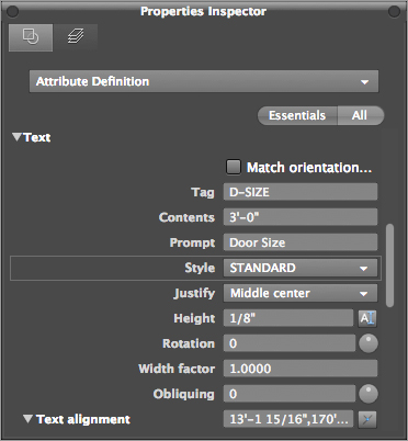
6. Highlight the Tag value to the right, and type D-SIZE↵. The attribute changes to reflect the change in the Tag value.
7. While still in the Text category, highlight the Prompt value, and type Door Size↵.
8. In the Contents field, type 3´-0˝↵. Metric users should type 90↵.
Make sure you press ↵ after entering a new value for the properties in the Properties Inspector palette. Pressing ↵ confirms your new entry.
You’ve just learned how to edit an attribute definition. Now you’ll make changes to the other attribute definitions:
1. Press Esc twice so that no attribute is selected, and then click the next attribute down so you can display its properties in the Properties Inspector palette.
2. Continue to edit this and the rest of the attribute definition properties by using the attribute settings listed in Table 12-1. To do this, repeat steps 4 through 8 of the preceding exercise for each attribute definition, replacing the Tag and Prompt values with those shown in Table 12-1. Also, make sure all but the original attributes have the Invisible option set to Yes.
3. When you’ve finished editing the attribute definition properties, close the Properties Inspector.
Table 12-1: Attributes for the door-type symbol
| Tag | Prompt | Content Value |
| D-NUMBER | Door number | - |
| D-THICK | Door thickness | - |
| D-RATE | Fire rating | - |
| D-MATRL | Door material | - |
| D-CONST | Door construction | - |
| Make sure the Invisible option is selected for the attributes in this table. | ||
When you later insert a file or a block containing attributes, the attribute prompts will appear in the order that their associated definitions were created. If the order of the prompts at insertion time is important, you can control it by editing the attribute definitions so their creation order corresponds to the desired prompt order. You can also control the order by using the Block Attribute Manager, which you’ll look at later in this chapter.
Order Does Matter
The order in which you select the attributes may not necessarily be the order in which the attribute prompts will appear when you insert the block with attributes. If you select the attributes with a window and start from the bottom up, your attribute order will start at the bottom. So it is best practice to pick the attributes one by one in the order you want them to be displayed. There are methods of changing the order and they will be discussed later in this chapter.
Turning the Attribute Definitions into a Block
You need to perform one more crucial step before these attribute definitions can be of any use. You need to turn the attribute definitions into a block, along with the circle:
1. Click the Create tool in the Tool Sets palette, or enter B↵.
2. In the Define Block dialog box, enter S-DOOR for the name.
3. In the Base Point group, click Pick Point, and then use the Center osnap to select the center of the circle.
4. In the Source Objects group, click Select Objects, and select the circle and all the attributes from the top to the bottom. Press ↵ when you’ve completed your selection.
5. In the Block Behavior group, click the Annotative check box. This ensures that the block is scaled to the appropriate size for the scale of the drawing into which it’s inserted.
6. Click Create Block. When the Edit Attribute dialog box opens, click Confirm to close it.
7. The attributes and the circle are now a block called S-DOOR. You can delete the S-DOOR block on your screen.
Understanding Attribute Definition Modes
The Attribute Definition dialog box includes several choices in the Attribute Options group; you’ve used one of these modes to see what it does. You won’t use any of the other modes in this chapter, but here is a list describing all the modes for your reference:
Invisible Controls whether the attribute is shown as part of the drawing.
Constant Creates an attribute that doesn’t prompt you to enter a value. Instead, the attribute has a constant, or fixed, value you give it during creation. Constant mode is used when you know you’ll assign a fixed value to an object. After constant values are set in a block, you can’t change them by using the standard set of attribute-editing commands.
Verify Causes AutoCAD to review the attribute values you enter at insertion time and to ask you whether they’re correct. This option appears only when the Edit Attribute dialog box is turned off (the Attdia system variable is set to 0).
Preset Causes AutoCAD to assign the default value to an attribute automatically when its block is inserted. This saves time because a preset attribute won’t prompt you for a value. Unlike attributes created in Constant mode, a preset attribute can be edited.
Lock Location Prevents the attribute from being moved from its original location in the block when you’re grip editing.
Multiple Lines Allows the attribute to contain multiple lines of text, similar to Mtext objects. When this option is turned on, you can specify a text boundary width.
Later in this chapter, you’ll see how to make an invisible attribute visible.
Once you’ve created the block, you can place it anywhere in the drawing using the Insert command or the Insert tool on the Tool Sets palette. You’ll insert this block in another location in the drawing. If you want to use the block in other drawings, you can use the Wblock command to save the block as a drawing file.
Inserting Blocks Containing Attributes
Earlier in this chapter, you created a door-type symbol at the desired size for the printed symbol. This size is known as the paper size. Because you turned on the Annotative option for the attribute and block, you can use the Annotation Scale setting to have the block insert at the appropriate size for the scale of the drawing. The following steps demonstrate the process of inserting a block that contains attributes. First, set up your view and annotation scale in preparation to insert the blocks:
1. Turn on Attribute Dialog mode by entering ATTDIA↵ 1↵ at the Command prompt. This enables you to enter attribute values through a dialog box in the next exercise. Otherwise, you’d be prompted for the attribute values in the Command Line palette.
2. Select 1⁄8˝=1´-0˝ (1:100 for metric users) from the Annotation Scale pop-up list in the status bar. This ensures that the block appears at the proper size for the drawing scale.
3. Type V↵ R↵ FIRST↵. This is a view that has been saved in this drawing. (See “Taking Control of the AutoCAD Display” in Chapter 7 for more on saving views.)
4. Be sure the Ceiling and Flr-pat layers are off. Normally, in a floor plan, the door headers aren’t visible anyway and their appearance will interfere with the placement of the door-reference symbol.
5. Finally, you can begin to place the blocks in the drawing. Click the Insert tool on the Tool Sets palette or type I↵ to open the Insert Block dialog box.
6. Select S-DOOR from the Blocks pop-up list.
7. Click the Show Insertion Options disclosure triangle. In the Insertion Point group, and make sure the Specify On-Screen option is turned on.
8. In the Rotation group, make sure the Input angle option is selected and the angle is 0 (zero).
9. In the Scale group, make sure the Uniform Scale check box is selected; then click Insert.
Now you’re ready to place the block in your drawing in the appropriate locations and enter the attribute values.
10. AutoCAD is waiting for you to select a location for the symbol. To place the symbol, click in the doorway of the lower-left unit, near coordinate 41´-3˝,72´-4˝. Metric users should use coordinate 1256,2202. When you click the location, the Edit Attributes dialog box opens (Figure 12-4).
11. In the Door Type input box, enter A and press the Tab key. Note that this is the prompt you created. Note also that the default value is the hyphen you specified. Attribute data is case sensitive, so any text you enter in all capital letters is stored in all capital letters.
12. In the Door Number input box, change the hyphen to 116. Continue to change the values for each input box as shown in Table 12-2.
Figure 12-4:The Edit Attributes dialog box

Table 12-2: Attribute values for the typical studio entry door
| Prompt | Value |
| Door Type | A |
| Door Size | 3´-0˝ (90 cm for metric) |
| Door Number | (Same as room number; see Figure 12-6.) |
| Door Thickness | 1¾˝ (4 cm for metric) |
| Fire Rating | 20 min. |
| Door Material | Wood |
| Door Construction | Solid core |
13. When you’re finished changing values, click Confirm and the symbol appears. The only attribute you can see is the one you selected to be visible: the door type.
14. Add the rest of the door-type symbols for the apartment entry doors by copying or arraying the door symbol you just inserted. You can use the previously saved views found in the 3D Navigation drop-down list in the View tab’s Views panel to help you get around the drawing quickly. Don’t worry that the attribute values aren’t appropriate for each unit; you’ll see how to edit the attributes in the next section.
In addition to the S-DOOR block, you’ll need a block for the room number. To save some time, I’ve included a block called S-APART that contains a rectangle and a single attribute definition for the room number (see Figure 12-5).
Figure 12-5:The room-number symbol

Do the following to insert the room-number block:
1. Click the Insert tool from the Tool Sets palette, and select S-APART from the Name pop-up list.
2. Make sure the Specify On-Screen setting is turned on only for the insertion point, and then click Insert.
3. Insert the S-APART block into the lower-left unit. Give the attribute of this block the value 116.
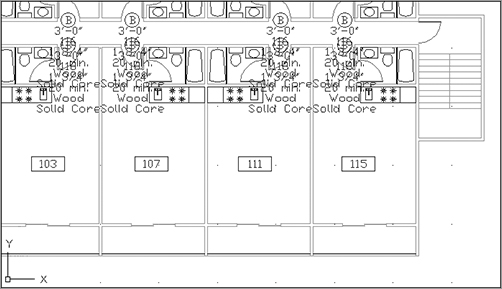
4. Copy or array the S-APART block so there is one S-APART block in each unit. You’ll learn how to modify the attributes to reflect their proper values in the following section. Figure 12-6 shows what the view should look like after you’ve entered the door symbols and the apartment numbers.
Figure 12-6:An overall view of the plan with door symbols and apartment numbers added

Because drawings are usually in flux even after construction or manufacturing begins, you’ll eventually have to edit previously entered attributes. In the example of the apartment building, many things can change before the final set of drawings is completed.
Attributes can be edited individually or globally—you can edit several occurrences of a particular attribute tag all at one time. In the following sections, you’ll use both individual and global editing techniques to make changes to the attributes you’ve entered so far. You’ll also practice editing invisible attributes.
Editing Attribute Values One at a Time
AutoCAD offers an easy way to edit attributes one at a time through a dialog box. The following exercise demonstrates this feature:
1. Type V↵ R↵ FIRST↵ to restore the First view.
2. Double-click the apartment number attribute in the unit just to the right of the first unit in the lower-left corner to open the Enhanced Attribute Editor (Figure 12-7).
Figure 12-7:The Enhanced Attribute Editor

3. Change the value in the Value input box to 112, and click Save to make the change.
4. Do this for each room, using Figure 12-8 as a reference for assigning room numbers.
5. Go back and edit the door number attribute for the S-DOOR blocks. Give each door the same number as the room number it’s associated with. Again, see Figure 12-8 for the room numbers.
Figure 12-8:Apartment numbers for one floor of the studio apartment building

Editing Attribute Text Formats and Properties
You may have noticed that the Enhanced Attribute Editor in the preceding exercise has three tabs: Attribute, Text Options, and Properties. When you double-click a block containing attributes, the Enhanced Attribute Editor dialog box opens at the Attribute tab. You can use the other two tabs to control the size, font, color, and other properties of the selected attribute.
The Text Options tab (Figure 12-9) lets you alter the attribute text style, justification, height, rotation, width factor, and oblique angle. (See Chapter 9, “Adding Text to Drawings,” for more on these text options.)
Figure 12-9:The Enhanced Attribute Editor’s Text Options tab

The Properties tab (Figure 12-10) lets you alter the attribute’s layer, linetype, color, line weight (effective only on AutoCAD fonts), and plot style assignments.
In the previous exercise, you edited a block containing a single attribute. Double-clicking a block that contains multiple attributes, such as the S-DOOR block, opens the Enhanced Attribute Editor dialog box at the Attribute tab. This tab displays all the attributes regardless of whether they’re visible, as shown in Figure 12-11. You can then edit the value, formats, and properties of the individual attributes by highlighting the attribute in the Attribute tab and using the other tabs to make changes. The changes you make affect only the attribute you’ve highlighted in the Attribute tab.
Figure 12-10:The Enhanced Attribute Editor’s Properties tab
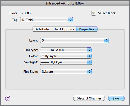
Figure 12-11:The Enhanced Attribute Editor showing the contents of a block that contains several attributes

The Enhanced Attribute Editor lets you change attribute values, formats, and properties one block at a time, but as you’ll see in the next section, you can also make changes to several attributes at once.
Moving the Location of Attributes
If you want to change the location of individual attributes in a block, you can move attributes by using grips. Click the block to expose the grips, and then click the grip connected to the attribute. Or, if you’ve selected several blocks, click the attribute grips, and then move the attributes to their new location. They are still attached to their associated blocks. If you don’t see grips appear for the attributes, then the attribute definition has its Lock Position property turned on. This is a setting that is available when you create the attribute in the Attribute Definition dialog box.
Making Global Changes to Attribute Values
At times, you’ll want to change the value of several attributes in a file so they’re all the same value. You can use the Edit Multiple Attributes option to make global changes to attribute values.
Suppose you decide you want to change all the entry doors to a type designated as B rather than A. Perhaps door type A was an input error or type B happens to be better suited for an entry door. The following exercise demonstrates how this is done:
1. Type V↵ R↵ FOURTH↵. This restores a saved view in the drawing called Fourth. (Views are covered in Chapter 7, “Mastering Viewing Tools, Hatches, and External References.”) Pan your view down so you can see the eight door-reference symbols for this view.
2. Click Multiple from the Edit Attribute flyout on the Tool Sets palette, or type -ATTEDIT↵ at the Command prompt. (Alternatively, you can type in -ATE.) Make sure you include the hyphen at the beginning.
3. At the Edit Attributes one at a time? [Yes/No] <Y>: prompt, enter N↵ for No. You see the message Performing global editing of attribute values. This tells you that you’re in Global Edit mode.
4. At the Edit only attributes visible on screen? [Yes/No] <Y>: prompt, press ↵. As you can see from this prompt, you have the option to edit all attributes, including those out of the view area. You’ll get a chance to work with this option in the next exercise.
5. At the Enter block name specification <*>: prompt, press ↵. Optionally, you can enter a block name to narrow the selection to specific blocks.
6. At the Enter attribute tag specification <*>: prompt, press ↵. Optionally, you can enter an attribute tag name to narrow your selection to specific tags.
7. At the Enter attribute value specification <*>: prompt, press ↵. Optionally, you can narrow your selection to attributes containing specific values.
8. At the Select Attributes: prompt, select the door-type symbol’s attribute value for units 103 to 115. You can use a window to select the attributes if you prefer. Press ↵ when you’ve finished your selection.
9. At the Enter string to change: prompt, enter A↵.
10. At the Enter new string: prompt, enter B↵. The door-type symbols all change to the new value.
In step 8, you were asked to select the attributes to be edited. AutoCAD limits the changes to those attributes you select. If you know you need to change every attribute in your drawing, you can do so by answering the series of prompts in a slightly different way, as in the following exercise:
1. Try the same procedure again, but this time enter N for the first prompt and N again at the Edit only attributes visible on screen? [Yes/No] <Y>: prompt (step 4 in the previous exercise). The message Drawing must be regenerated afterwards appears.
2. Once again, you’re prompted for the block name, the tag, and the value (steps 5, 6, and 7 in the previous exercise). Respond to these prompts as you did earlier.
3. You then get the message 128 attributes selected. This tells you the number of attributes that fit the specifications you just entered.
4. At the Enter string to change: prompt, enter A↵ to indicate you want to change the rest of the A attribute values.
5. At the Enter new string: prompt, enter B↵. A series of Bs appears, indicating the number of strings that were replaced.
In the previous exercise, AutoCAD skipped the Select Attribute: prompt and went directly to the String to change: prompt. AutoCAD assumes that you want it to edit every attribute in the drawing, so it doesn’t bother asking you to select specific attributes.
Making Invisible Attributes Visible
You can globally edit invisible attributes, such as those in the door-reference symbol, by using the tools just described. You may, however, want to be more selective about which invisible attribute you want to modify. Optionally, you may want to make invisible attributes temporarily visible for other editing purposes.
This exercise shows how you can make invisible attributes visible:
1. Type ATTDISP↵ ON↵. Your drawing looks like Figure 12-12.
Figure 12-12:The drawing with all the attributes visible. (Door-type symbols are so close together that they overlap.)
2. At this point, you could edit the invisible attributes individually, as in the first attribute-editing exercise. For now, set the attribute display back to Normal. Type ATTDISP↵ N↵.
You’ve seen the results of the On and Normal options. The Off option makes all attributes invisible regardless of the mode used when they were created.
Because the attributes weren’t intended to be visible, they appear to overlap and cover other parts of the drawing when they’re made visible. Remember to turn them back off when you’re done reviewing them.
Using Spaces in Attribute Values
At times, you may want the default value to begin with a blank space. This enables you to specify text strings more easily when you edit the attribute globally. For example, suppose you have an attribute value that reads 3334333. If you want to change the first 3 in this string of numbers, you have to specify 3334 when prompted for the string to change. Then, for the new string, you enter the same set of numbers again, but with the first 3 changed to the new number. If you only specify 3 for the string to change, AutoCAD will change all the 3s in the value. If you start with a space, as in _3334333 (I’m using an underscore here only to represent the space; it doesn’t mean you type an underscore character), you can isolate the first 3 from the rest by specifying _3 as the string to change (again, type a space instead of the underscore).
You must enter a backslash character () before the space in the default value to tell AutoCAD to interpret the space literally rather than as a press of the spacebar (which is equivalent to pressing ↵).
Making Global Format and Property Changes to Attributes
While we’re on the subject of global editing, you should know how to make global changes to the format and properties of attributes. Earlier you saw how to make format changes to individual attributes by using the Enhanced Attribute Editor dialog box. Let’s use the Edit Attributes tool to make global changes:
Follow these steps to make the global changes:
1. Click the arrow next to Attributes on the Tool Sets palette to reveal the Block panel. Choose the Manage Attributes tool. The Block Attribute Manager dialog box will open. You can also enter BATTMAN↵.
2. Select S-Apart from the Block pop-up list at the top of the dialog box. This list displays all the blocks that contain attributes. The only attribute defined for the selected block is displayed in the list box below it.

3. Double-click an attribute value to open the Attribute Editor dialog box. The Attribute Editor dialog box is nearly identical to the Enhanced Attribute Editor you saw earlier.

4. Click the Properties tab, select Red from the Color pop-up list, and click OK.
5. Click Update Blocks to exit the Block Attribute Manager dialog box.
The Attribute Editor dialog box you saw in this exercise offers a slightly different set of options from those in the Enhanced Attribute Editor dialog box. In the Attribute tab of the Attribute Editor dialog box, you can change some of the mode settings for the attribute, such as visibility and the Verify and Preset modes. You can also change the Tag, Prompt, and Default values. In contrast, the Attribute tab in the Enhanced Attribute Editor dialog box enables you to change the attribute value but none of the other attribute properties.
Other Block Attribute Manager Options
The Block Attribute Manager dialog box includes a few other options that weren’t covered in the exercises. Here’s a rundown of the Remove (–) and Synchronize Blocks buttons as well as the option to move attribute names up or down:
Remove The Remove button looks like a minus sign (–). Clicking this button removes the selected attribute from the block. If you didn’t mean to click this button, click the Discard Changes button.
Synchronize Blocks This option updates attribute properties such as order, text formatting, mode, and so on. It can also be used to globally update blocks that have had new attribute definitions added or deleted. It doesn’t affect the individual attribute values.
Move up and move down It’s not a true button, but you can click on an attribute name and while depressing the mouse button, drag it to a new location. If you move an item down the list, the item changes its position when viewed using the Edit Attribute dialog box (Ddatte command) or when you’re viewing the attribute’s properties in the Enhanced Attribute Editor dialog box (Eattedit command). Of course, this has an effect only on blocks containing multiple attributes.
Redefining Blocks Containing Attributes
Attributes act differently from other objects when they’re included in redefined blocks. Normally, blocks that have been redefined change their configuration to reflect the new block definition. But if a redefined block contains attributes, the attributes maintain their old properties, including their position in relation to other objects in the block. This means the old attribute position, style, and so on don’t change even though you may have changed them in the new definition.
Fortunately, AutoCAD offers a tool that’s specifically designed to let you update blocks with attributes. The following steps describe how to update attribute blocks:
1. Before you use the command to redefine an attribute block, you must create the objects and attribute definitions that will make up the replacement attribute block. The simplest way to do this is to explode a copy of the attribute block you want to update (the Explode command is covered in Chapter 4, “Organizing Objects with Blocks and Groups”). This ensures that you have the same attribute definitions in the updated block.
2. Make your changes to the exploded attribute block.
Explode Attribute Blocks at a 1-to-1 Scale
Before you explode the attribute block copy, be sure it’s at a 1-to-1 scale. This is important because if you don’t use the original size of the block, you could end up with all your new attribute blocks at the wrong size. Also be sure you use a marker device, such as a line, to locate the insertion point of the attribute block before you explode it. This will help you locate and maintain the original insertion point for the redefined block.
3. Type AT↵.
4. At the Enter name of block you wish to redefine: prompt, enter the appropriate name.
5. At the Select objects: prompt, select all the objects, including the attribute definitions, that you want to include in the revised attribute block.
6. At the Specify insertion base point of new Block: prompt, pick the same location used for the original block.
After you pick the insertion point, AutoCAD takes a few seconds to update the blocks. The amount of time depends on the complexity of the block and the number of times the block occurs in the drawing. If you include a new attribute definition with your new block, it too is added to all the updated blocks, with its default value. Attribute definitions that are deleted from your new definition are removed from all the updated blocks.
Create attributes. Attributes are a great tool for storing data with drawn objects. You can include as little or as much data as you like in an AutoCAD block.
Master It What is the name of the object you must include in a block to store data?
Edit attributes. The data you include in a block is easily changed. You may have several copies of a block, each of which must contain its own unique sets of data.
Master It What is the simplest way to gain access to a block’s attribute data?