
Chapter 15
Laying Out Your Printer Output
Your set of drawings for the studio apartment building would probably include a larger-scale, more detailed drawing of the typical unit plan. You already have the beginnings of this drawing in the form of the Unit file.
As you’ve seen, the notes and dimensions you entered into the Unit file can be turned off or frozen in the Plan file so they don’t interfere with the graphics of the drawing. The Unit file can be part of another drawing file that contains more detailed information about the typical unit plan at a larger scale. To this new drawing, you can add notes, symbols, and dimensions. Whenever the Unit file is altered, you update its occurrence in the large-scale drawing of the typical unit as well as in the Plan file. The units are thus quickly updated, and good coordination is ensured among all the drawings for your project.
Now, suppose you want to combine drawings that have different scales in the same drawing file—for example, the overall plan of one floor plus an enlarged view of one typical unit. You can do so using the layout views and a feature called Paper Space.
In this chapter, you’ll learn how to do the following:
- Understand Model Space and Paper Space
- Work with Paper Space viewports
- Create odd-shaped viewports
- Understand line weights, linetypes, and dimensions in Paper Space
Understanding Model Space and Paper Space
So far, you’ve looked at ways to get around in your drawing while using a single view. This single-view representation of your AutoCAD drawing is called Model Space. You can also set up multiple views of your drawing by using what are called floating viewports. You create floating viewports in layout views in what is called Paper Space.
To get a clear understanding of Model Space and Paper Space, imagine that your drawing is actually a full-size replica or model of the object you’re drawing. Your computer screen is your window into a “room” where this model is being constructed, and the keyboard and mouse are your means of access to this room. You can control your window’s position in relation to the object through the use of Pan, Zoom, View, and other display-related commands. You can also construct or modify the model by using drawing and editing commands. Think of this room as your Model Space.
You’ve been working on your drawings by looking through a single window into Model Space. Now, suppose you have the ability to step back and add windows with different views looking into your Model Space. The effect is as if you have several video cameras in your Model Space room, each connected to a different monitor. You can view all your windows at once on your computer screen or enlarge a single window to fill the entire screen. Further, you can control the shape of your windows and easily switch from one window to another. This is what Paper Space is like.
Paper Space lets you create and display multiple views of Model Space. Each view window, called a viewport, acts like an individual virtual screen. One viewport can have an overall view of your drawing, while another can be a close-up. You can also control layer visibility individually for each viewport and display different versions of the same area of your drawing. You can move, copy, and stretch viewports and even overlap them. You can set up another type of viewport, called the tiled viewport, in Model Space. Chapter 20, “Using Advanced 3D Features,” discusses this type of viewport.
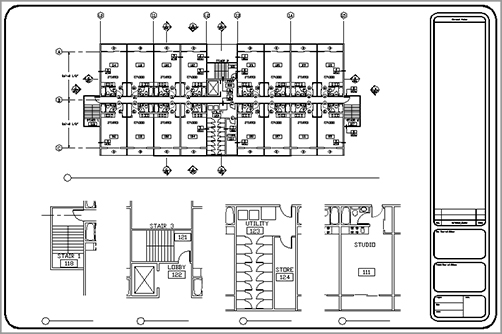
One of the most powerful features of Paper Space is the ability to print several views of the same drawing on one sheet of paper. You can also include graphic objects such as borders and notes that appear only in Paper Space. In this function, Paper Space acts much like a page-layout program such as QuarkXPress or Adobe InDesign. You can paste up different views of your drawing and then add borders, title blocks, general notes, and other types of graphic and textual data. Figure 15-1 shows the Plan drawing set up in Paper Space mode to display several views.
Figure 15-1:Different views of the same drawing in Paper Space
Switching from Model Space to Paper Space
You can get to Paper Space by selecting a layout from the Layouts pop-up menu on the status bar or clicking on any of the layout thumbnails in the Show Drawings & Layouts tool on the status bar.

If you don’t see the Show Drawings & Layouts or Model/Layout tools, right-click in a blank area of the status bar and click QuickView from the shortcut menu. The Show Drawings & Layouts and Model/Layout tools make up the QuickView tools.
Let’s start with the basics of switching between model and Paper Space:
1. Open the Xref-1 file you saved from the last chapter, and ensure that your display shows the entire drawing. You can also use 15-xref1.dwg or 15-xref1-metric.dwg.
2. Click the Model/Layout pop-up menu in the status bar and select Layout1. The pop-up menu is now labeled Layout1. You will see your drawing appear in a kind of page preview view (Figure 15-2).
Figure 15-2:Your drawing in a page preview view

3. Click the Model/Layout pop-up menu in the status bar and select Model to return to Model Space.
This brief exercise shows you how quickly you can shift between Model Space and a Paper Space layout by using the Model/Layout pop-up menu. The QuickView tool lets you do the same thing but offers a little more help. Try the following to see how the QuickView tool works:
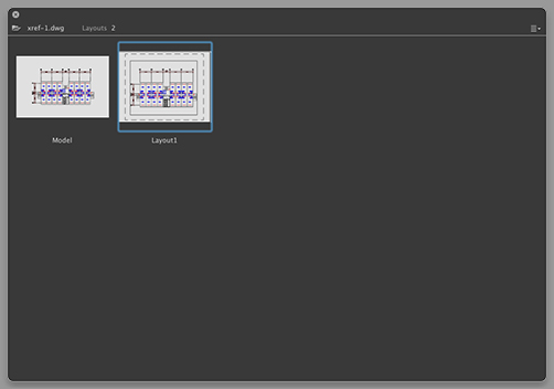
1. Click the Show Drawings & Layouts tool in the status bar to open the QuickView dialog box. (Figure 15-3).
2. Double-click the thumbnail labeled Layout1. Notice that the drawing area changes to show the Paper Space of Layout1.
3. Click the Show Drawings & Layouts tool again, but this time double-click the thumbnail labeled Model.
If you prefer, you can use command aliases to switch between Model Space and Paper Space. Enter TM↵ 1↵ to go to Model Space. Enter TM↵ 0↵ to go to Paper Space.
Figure 15-3:The Quickview dialog box
Setting the Size of a Paper Space Layout
I mentioned that Paper Space is like a page layout program, and you saw how a Paper Space layout looks like a print preview. You can set up your layout for a specific set of printer settings, including the paper size and printer.
Let’s continue our look at Paper Space by seeing how a Paper Space layout can be set up for your printer:
1. Click the Show Drawings & Layouts tool.
2. Right-click Layout1, and choose Page Setup to open the Page Setup Manager dialog box. Notice that the name of the current layout is shown in the list of current page setups (Figure 15-4).
3. Click the Modify action menu and select Edit to open the Page Setup dialog box.
Note that if you do not have a printer configured, a warning box will appear informing you of that. Click OK to dismiss the warning dialog box.
4. Select the Letter paper-size option from the Paper Size pop-up menu. Metric users should select A4 (210 mm 297 mm). The paper size you select here determines the shape and margin of the Paper Space layout area.
5. Select a printer from the Printer name pop-up menu.
6. Click OK to close the Page Setup dialog box, and then click Close to close the Page Setup Manager dialog box.
AutoCAD bases the Paper Space layout on the paper size and printer you specify in steps 4 and 5. The area shown in Paper Space reflects the area of the paper size you selected in step 4, and the paper margin shown by a dashed line is determined by the printer. If for some reason you need to change the paper size, repeat steps 2 through 5. You can also store the way you’ve set up your Paper Space layout using the Page Setup Manager dialog box you saw in step 2. See Chapter 8, “Introducing Printing and Layouts,” for more on this feature.
Figure 15-4:The Page Setup Manager dialog box

Creating New Paper Space Viewports
As you saw in Chapter 8, the different look of the layout view tells you that you’re in Paper Space. You also learned that a viewport is automatically created when you first open a layout view. The layout viewport displays an overall view of your drawing to no particular scale.
In this section, you’ll work with multiple viewports in Paper Space instead of just the default single viewport you get when you open the layout view.
This first exercise shows you how to create three new viewports at once:
1. Click the viewport border to select it. The viewport border is the solid rectangle surrounding your drawing, just inside the dashed rectangle.
2. Click the Erase tool in the Tool Sets palette to erase the viewport. Your drawing disappears. Don’t panic; remember that the viewport is like a window to Model Space. The objects in Model Space are still there.
3. Chose View Viewports New Viewports to open the Viewports dialog box. You can also type VPORTS↵. This dialog box contains a set of predefined viewport layouts (Figure 15-5). You’ll learn more about the Viewports dialog box and its options in Chapter 20.
Figure 15-5:The Viewports dialog box

4. Click the Three: Above option in the Standard Viewports list box. The box to the right shows a sample view of the Three: Above layout you selected.
5. Click OK. The Specify first corner or [Fit] <Fit>: prompt appears.
6. Press ↵ to accept the default Fit option. The Fit option fits the viewport layout to the maximum area allowed in your Paper Space view. Three rectangles appear in the formation, as shown in Figure 15-6. Each of these is a viewport to your Model Space. The viewport at the top fills the whole width of the drawing area; the bottom half of the screen is divided into two viewports.
When you create new viewports, AutoCAD automatically fills them with the extents of your Model Space drawing. You can specify an exact scale for each viewport, as you’ll see later.
Notice that the dashed line representing your paper margin has disappeared. That’s because the viewports are pushed to the margin limits, thereby covering the dashed line.
You could have kept the original viewport that appeared when you first opened the Layout1 view and then added two new viewports. Completely replacing the single viewport is a bit simpler because the Viewports dialog box fits the viewports in the allowed space for you.
After you’ve set up a Paper Space layout, it remains part of the drawing. You may prefer to use Model Space for doing most of your drawing and then use Paper Space layouts for setting up views for printing. Changes that you make to your drawing in Model Space will automatically appear in your Paper Space layout viewports.
Figure 15-6:The newly created viewports

Reaching inside Viewports
Now, suppose you need access to the objects in the viewports in order to adjust their display and edit your drawing. Try these steps:
1. Double-click inside a viewport. This gives you control over Model Space even though you’re in Paper Space. (You can also enter MS↵ as a command alias to enter Model Space while on a layout.)
The first thing you notice is that the UCS icon changes back to its L-shaped arrow form. It also appears in each viewport, as if you had three AutoCAD drawing windows instead of just one.
2. Move your cursor over each viewport. In one of the viewports, the cursor appears as the AutoCAD crosshair cursor, whereas in the other viewports it appears as an arrow pointer. The viewport that shows the AutoCAD cursor is the active one; you can pan, zoom, and edit objects in the active viewport.
3. Click in the lower-left viewport to activate it.
4. Click Zoom on the status bar and then type W↵, and place a window selection around the elevator area. You can also type Z↵ W↵.
5. Click in the lower-right viewport, and click Zoom Window to enlarge your view of a typical unit. You can also use the Pan and Zoom Realtime tools. If you don’t see the UCS icon, it has been turned off. Type UCSICON↵ ON↵ to turn it on. See Chapter 20 for more on the UCS icon.
You can move from viewport to viewport even while you’re in the middle of most commands. For example, you can issue the Line command, pick the start point in one viewport, go to a different viewport to pick the next point, and so on. To activate a different viewport, you click inside the viewport (see Figure 15-7).
Figure 15-7:The three viewports, each with a different view of the plan
Switching between Viewports
I’ve found that users will have a need to overlap viewports from time to time. When they do this, they are often at a loss over how to switch between the overlapping viewports, especially when one is completely surrounded by another or they are exactly the same size and in the same position. In this situation, you can move between viewports by pressing ![]() -R repeatedly until you get to the viewport you want.
-R repeatedly until you get to the viewport you want.
You’ve seen how you can zoom into a viewport view, but what happens when you use the Zoom command while in Paper Space? Try the following exercise to find out:
1. Double-click an area outside the viewports to get out of Model Space.
2. Click Zoom on the status bar and then press ↵ to activate the Zoom Realtime option, and then, using your mouse, zoom in to the Paper Space view. The entire view enlarges, including the views in the viewports.
3. Right-click and choose Exit. Click Zoom on the status bar and then type A↵ or enter Z↵ A↵ to return to the overall view of Paper Space.
This brief exercise showed that you can use the Zoom tool in Paper Space just as you would in Model Space. All the display-related commands are available, including the Zoom Realtime command.
Working with Paper Space Viewports
Paper Space is intended as a page-layout or composition tool. You can manipulate viewports’ sizes, scale their views independently of one another, and even set layering and linetype scales independently.
Let’s try manipulating the shape and location of viewports:
1. Make sure Object Snap is turned off in the status bar.
2. Make sure you’re not in any viewports on the Paper Space layout. Then click the bottom edge of the lower-left viewport to expose its grips (see the top image in Figure 15-8).
Figure 15-8:Stretching, erasing, and moving viewports

3. Click the upper-right grip, and drag it to the location shown in the top image in Figure 15-8.
4. Press the Esc key, and erase the lower-right viewport by selecting it and clicking Erase on the Tool Sets palette or by pressing the Delete key.
5. Move the lower-left viewport so it’s centered in the bottom half of the window, as shown in the bottom image in Figure 15-8.
In this exercise, you clicked the viewport edge to select it for editing. If, while in Paper Space, you attempt to click the image in the viewport, you won’t select anything. Later, you’ll see that you can use the osnap modes to snap to parts of the drawing image in a viewport.
Because viewports are recognized as AutoCAD objects, you can manipulate them by using all the editing commands, just as you would manipulate any other object. In the previous exercise, you moved, stretched, and erased viewports.
Next, you’ll see how layers affect viewports:
1. Create a new layer called Vport.
2. In the Properties Inspector palette, change the viewport borders to the Vport layer.
3. Turn off the Vport layer. The viewport borders disappear.
4. After reviewing the results of step 3, turn the Vport layer back on.
You can assign a layer, a color, a linetype, and even a line weight to a viewport’s border. If you put the viewport’s border on a layer that has been turned off or frozen, that border becomes invisible, just like any other object on such a layer. Or you can put the viewport border on a nonprinting layer so the border will be visible while you’re editing. Making the borders invisible or putting them on a nonprinting layer is helpful when you want to compose a final sheet for printing. Even when turned off, the active viewport has a heavy border around it when you switch to Model Space, and all the viewports still display their views.
Scaling Views in Paper Space
Paper Space has its own unit of measure. You’ve already seen how you’re required to specify a paper size when opening a layout view to a Paper Space view. When you first enter Paper Space, regardless of the area your drawing occupies in Model Space, you’re given limits that are set by the paper size you specify in the Page Setup dialog box. If you keep in mind that Paper Space is like a paste-up area that is dependent on the printer you configured for AutoCAD, this difference of scale becomes easier to comprehend. Just as you might paste up photographs and maps representing several square miles onto an 11˝--17˝ board, so can you use Paper Space to paste up views of scale drawings representing city blocks or houses on an 8½˝-- 11˝ sheet of paper. But in AutoCAD, you have the freedom to change the scale and size of the objects you’re pasting up.
While in Paper Space, you can edit objects in Model Space through a viewport. You can then click a viewport and edit in that viewport. In this mode, objects that were created in Paper Space can’t be edited. Double-click outside a viewport to go back to the Paper Space.
If you want to be able to print your drawing at a specific scale, you must indicate a scale for each viewport. Viewport scales are set in a way similar to the annotation scale in the model layout. Let’s look at how to put together a layout in Paper Space and still maintain accuracy of scale:
1. Make sure you’re in Paper Space. You can tell by the shape and location of the UCS icon. If it looks like a triangle in the lower-left corner of the layout view, then you are in Paper Space.
2. Click the topmost viewport’s border to select it.
3. In the lower-right corner of the AutoCAD window, click the Viewport Scale pop-up menu, and select 1⁄32˝ = 1´-0˝. Metric users should click Custom and add a custom scale of 1:400. Then select the 1:400 scale from the Viewport Scale pop-up menu. Notice how the view in the top viewport changes.
4. Press the Esc key once to clear the selection in the viewport.
5. Click the lower viewport border.
6. Click the VP Scale pop-up menu again, and select 3⁄16˝ = 1´-0˝. Metric users should select 1:100. The view in the viewport changes to reflect the new scale (see Figure 15-9).
Figure 15-9:Paper Space viewport views scaled to 1⁄32˝ = 1´-0˝ and 3⁄16˝ = 1´-0˝ (1:400 and 1:100 for metric users)

It’s easy to adjust the width, height, and location of the viewports so they display only the parts of the unit you want to see. While in Paper Space, use the Stretch, Move, Scale, or Rotate command to edit any viewport border, or use the viewport’s grips to edit its size and shape. The view in the viewport remains at the same scale and location while the viewport changes in size. You can move and stretch viewports with no effect on the size and location of the objects in the view. When you rotate the viewport, the view inside the viewport will also rotate.
If you need to overlay one drawing on top of another, you can overlap viewports. Use the Osnap overrides to select geometry in each viewport, even while in Paper Space. This enables you to align one viewport on top of another at exact locations.
You can also add a title block in Paper Space at a 1:1 scale to frame your viewports and then print this drawing from Paper Space at a scale of 1:1. Your print appears just as it does in Paper Space, at the appropriate scale. Paper Space displays a dashed line to show you where the nonprintable areas occur near the edge of the paper.
While you’re working in Paper Space, pay close attention to the UCS icon. If it appears inside the viewing area, you are in a viewport. It’s easy to pan or zoom in a viewport accidentally when you intend to pan or zoom your Paper Space view. This can cause you to lose your viewport scaling or alignment with other parts of the drawing.
One way to prevent your viewport view from being accidentally altered is to turn on Display Lock. To do this, while in Paper Space, click a viewport border. Right-click to open the shortcut menu, and then choose Display Locked Yes. After the view is locked, you can’t pan or zoom within a viewport. This setting is also available in the viewport’s Properties Inspector palette.
Setting Layers in Individual Viewports
Another unique feature of Paper Space viewports is their ability to freeze layers independently. You can, for example, display the usual plan information in the overall view of a floor but show only the walls in the enlarged view of one unit.
You control viewport layer visibility through the Layers palette. You may have noticed that there are three snowflake icons for each layer listing. You’re already familiar with the snowflake icon farthest to the left. This is the Freeze/Thaw icon that controls the freezing and thawing of layers globally. Several columns to the right of that icon are two icons with transparent rectangles. These icons control the freezing and thawing of layers in individual viewports. Of this pair, the one on the left controls existing viewports and the one on the right controls settings for newly created viewports. Note that in the Layers palette and the menu bar, you will see New VP Freeze and VP Freeze. VP is another way of saying viewport.

To see all of the layer options, you may need to widen the Layers palette to view all the columns or display a layer property in the list. To do so, undock the palette, and then click and drag the border of the palette. Right-click a column header and choose the properties that you want to display.
This exercise shows you firsthand how the icon for existing viewports works:
1. Double-click inside a viewport to enter Model Space.
2. Activate the lower viewport.
3. If it is not already open, open the Layers palette (F-4).
4. Locate the COMMON|WALL layer, and then click its name to help you isolate it.
5. Click the column labeled VP Freeze for the selected layer. You may need to widen the Layers palette to do this. If VP Freeze does not display on the Layers palette, right-click the layer header and select VP Freeze. Click the column, which looks like a transparent rectangle under a snowflake. The icon appears in the COMMON|WALL layer, telling you that the layer is now frozen for the current viewport.
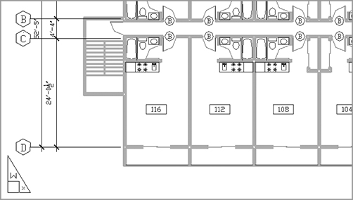
The Wall layer of the Common Xref becomes invisible in the current viewport. However, the walls remain visible in the other viewport (see Figure 15-10).
Figure 15-10:The drawing with the COMMON|WALL layer turned off in the active viewport

6. After reviewing the effects of the VP Freeze setting, go back to the Layers palette and thaw the COMMON|WALL layer by clicking the VP Freeze icon so it disappears.
7. Take a moment to study the drawing, and then save the Xref-1 file.
You may have noticed another column, with an identical snowflake icon next to the one you used in the previous exercise. This column controls layer visibility in any new viewports you create next rather than in existing viewports. This column might be turned off by default; if it is, right-click the column headers in the Layers palette and choose New VP Freeze.
In addition to setting the visibility of layers, you can set the other layer properties—such as color, linetype, and line weight—for each viewport. First, make sure you’re in Model Space for the viewport whose layers you want to set up, and then open the Layers palette. You can set the properties for the current viewport using the VP Freeze, VP Color, VP Linetype, VP Lineweight, VP Transparency, and VP Plot Style settings for each layer (Figure 15-11).
Figure 15-11:The VP Freeze, VP Color, VP Linetype, VP Lineweight, VP Transparency and VP Plot Style columns in the Layers palette

This section concludes the apartment building tutorial. Although you haven’t drawn the complete building, you’ve learned all the commands and techniques you need to do so. Figure 15-12 shows a completed plan of the first floor. To complete your floor plans and get some practice using AutoCAD, you may want to add the symbols shown in this figure to your Plan file.
Figure 15-12:A completed floor of the apartment building

Because buildings like this one often have the same plans for several floors, the plan for the second floor can also represent the third floor. Combined with the first floor, this gives you a three-level apartment building. This project might also have a ground-level garage, which would be a separate file. You can use the Col-grid.dwg file (which can be found on the book’s companion website, www.sybex.com/go/masteringautocadmac) in the new garage drawing that you create as a reference for dimensions. The other symbols can be blocks stored as files that you can retrieve in other files.
Masking Out Parts of a Drawing
Chapter 7, “Mastering Viewing Tools, Hatches, and External References,” described a method for using AutoCAD’s Draworder feature to hide floor patterns under equipment or furniture in a floor layout. You can use a similar method to hide irregularly shaped areas in a Paper Space viewport. This is desirable for plotting site plans, civil plans, or floor plans that require portions of the drawing to be masked out. You may also want to mask part of a plan that is overlapped by another to expose dimension or text data.
Creating and Using Multiple Paper Space Layouts
You’re not limited to just one or two Paper Space layouts. You can have as many as you want, with each layout set up for a different sheet size containing different views of your drawing. You can use this feature to set up multiple drawing sheets based on a single AutoCAD drawing file. For example, suppose a client requires full sets of plans in both 1⁄8˝ = 1´ scale and 1⁄16˝ = 1˝ scale. You can set up two layouts, each with a different paper size and viewport scale.
You can also set up different Paper Space layouts for the different types of drawings. A single drawing can contain the data for mechanical layout, equipment and furnishing, floor plans, and reflected ceiling plans. Although a project can require a file for each floor plan, a single file with multiple layout views can serve the same purpose.
To create new layout views, do the following:
1. Click the Show Drawings & Layouts tool in the status bar. The QuickView dialog box opens.
2. Click the menu on the upper right-hand corner of the QuickView dialog box to display the Layout options (see Figure 15-13). You can also right-click a thumbnail in the QuickView dialog box to display the options. Choose Create New Layout. The Create Layout dialog box appears with a default layout name (Layout2) for the new layout.
Figure 15-13:The Layout options

3. Click the Confirm button to add the new Layout2.
4. Double-click Layout2. The new layout appears with a single default viewport.
You’ve just seen how you can create a new layout using the Show Drawings & Layouts tool.
The Show Drawings & Layouts shortcut menu also includes the New Layout From Template option. The New Layout From Template option lets you create a Paper Space layout based on a layout saved in a drawing (DWG), drawing template (DWT), or DXF file. AutoCAD provides several drawing templates with standard layouts that include title blocks based on common sheet sizes.
To move a tab, simply click and drag it to where you want it to appear. Finally, if you want to duplicate, delete, or rename a layout, click the Show Drawings & Layouts tool and then right-click the layout you want to edit. You can then select the option from the shortcut menu that appears. If you select Delete, you’ll see a warning message telling you that AutoCAD will permanently delete the layout you have chosen to delete. Click OK to confirm your deletion.
In many situations, a rectangular viewport doesn’t provide a view appropriate for what you want to accomplish. For example, you might want to isolate part of a floor plan that is L-shaped or circular. You can create viewports for virtually any shape you need. You can grip edit a typical rectangular viewport to change its shape into a trapezoid or other irregular four-sided polygon. You can also use the Polygonal Viewport tool to create more complex viewport shapes, as the following exercise demonstrates.
Follow these steps to set up a layout view that shows only the lower apartment units and the elevators and stairs:
1. Choose View Viewports Polygonal Viewport from the menu bar.
2. Turn on Ortho Mode from the status bar.
3. Turn off Running Osnaps, and draw the outline shown in the top portion of Figure 15-14.
4. After you finish selecting points, type C↵ to close the polyline. The viewport changes to conform to the new shape.
Figure 15-14:Drawing a polygon outline for a viewport

5. Click the viewport border to expose its grips.
6. Click a grip, and move it to a new location. The viewport view conforms to the new shape.
The new viewport shape gives you more flexibility in isolating portions of a drawing. This can be especially useful if you have a large project that is divided into smaller sheets. You can set up several layout views, each displaying a different portion of the plan.
What if you want a viewport that isn’t rectilinear? This exercise shows you how to create a circular viewport:
1. Erase the viewport you just modified.
2. Draw a circle that roughly fills the layout.
3. Choose View Viewports Object from the menu bar. You can also type -VPORTS↵ O↵ (letter O, not the number zero).
4. Click the circle. The plan appears inside the circle, as shown in Figure 15-15.
Figure 15-15:A circular viewport

To simplify this exercise, you were asked to draw a circle as the basis for a new viewport. However, you aren’t limited to circles; you can use a closed polyline or spline of any shape. (See Chapter 17, “Drawing Curves,” for a detailed discussion of polylines and splines.) You can also use the Polygon tool to create a shape and then turn it into a viewport.
If you look carefully at the series of prompts for the previous exercise, you’ll notice that the Object tool invokes a command-line version of the Vports command (-vports). This command-line version offers some options that the standard Vports command doesn’t. The following options are available with the command-line version of Vports:
-vports
Specify corner of viewport or [ON/OFF/Fit/Shadeplot/Lock
Object/Polygonal/Restore/Layer/2/3/4] <Fit>:
You used two of the options—Polygonal and Object—in the two previous exercises.
Understanding Line Weights, Linetypes, and Dimensions in Paper Space
The behavior of several AutoCAD features depends on whether you’re in Paper Space or Model Space. The most visible of these features are line weights, linetypes, and dimensions. In the following sections, you’ll take a closer look at these features and see how to use them in conjunction with Paper Space.
Controlling and Viewing Line Weights in Paper Space
Line weights can greatly improve the readability of technical drawings. You can make important features stand out with bold line weights while keeping the noise of smaller details from overpowering a drawing. In architectural floor plans, walls are traditionally drawn with heavier lines so the outline of a plan can be easily read. Other features exist in a drawing for reference only, so they’re drawn in a lighter weight than normal.
In Chapter 8, you saw how to control line weights in AutoCAD by using plot style tables. You can apply either a named plot style table or a color plot style table to a drawing. If you already have a library of AutoCAD drawings, you may want to use color plot style tables for backward compatibility. AutoCAD also enables you to assign line weights directly to layers or objects and to view the results of your line-weight settings in Paper Space.
Here’s an exercise that demonstrates how to set line weights directly:
1. Open the Layers palette (F-4).
2. Right-click the layer list, and choose Select All.
3. Click the Lineweight column to open the Lineweight pop-up menu (Figure 15-16).
Figure 15-16:The Lineweight pop-up menu

4. Select 0.13 mm from the list. You’ve just assigned the 0.13 mm line weight to all layers.
5. Right-click the layer list again, and choose Clear All.
6. Click the Common|WALL layer, and F-click the Floor1|WALL layer to select these two layers.
7. Click the Lineweight column for either of the two selected layers to open the Lineweight pop-up menu again.
8. Select 0.40 mm from the list. You’ve just assigned the 0.40 mm line weight to the two selected layers.
9. Right-click the layer list and choose Clear All. Close the Layers palette or press F-4.
Although you set the line weights for the layers in the drawing, you need to make a few more changes to the file settings before they’re visible in Paper Space:
1. Click the Show/Hide Lineweight tool from the status bar.
2. Make sure you’re in Paper Space, and then zoom in to the drawing.
3. Type REA↵. The lines representing the walls are now thicker, as shown in Figure 15-17.
4. After reviewing the results of this exercise, close the file.
Figure 15-17:An enlarged view of the plan with line weights displayed
With the ability to display line weights in Paper Space, you have better control over your output. Instead of using a trial-and-error method to print your drawing and then checking your printout to see whether the line weights are correct, you can see the line weights on your screen.
This exercise showed you how to set line weights so they appear in Paper Space as they will when you print your drawing. If you normally print your drawings in black, you can go one step further and set all your layer colors to black to see how your plots will look. But you’ll need to save your layer settings so you can restore the layers to their original colors. Another way to view your drawing in black and white without affecting your layer settings is to use the color plot style table described in Chapter 8.
Line Weight Display Shortcut
When line-weight display is turned on, you see line weights in Model Space as well as in Paper Space. Line weights can be distracting while you work on your drawing in Model Space, but you can quickly turn them off by entering LWDISPLAY↵ OFF↵ at the Command prompt. Entering LWDISPLAY↵ ON↵ turns the line-weight display back on.
The Lineweight Settings Dialog Box
Another method of displaying line-weight settings is via the Lineweight Settings dialog box. Type LW↵ to open the Lineweight Settings dialog box shown in Figure 15-18.
Figure 15-18:The Lineweight Settings dialog box

The Lineweight Settings dialog box includes some settings that were not mentioned in Chapter 8’s discussion of line-weight settings. Here is a description of those settings for your reference:
Units You can choose between millimeters and inches for the unit of measure for line weights. The default is millimeters.
Default pop-up menu This pop-up menu lets you select the default line weight you see in the Layers palette. It’s set to 0.01˝ (0.25 mm) by default. You may want to lower the default line weight to 0.005˝ (0.13 mm) as a matter of course because most printers these days can print lines that size and even smaller.
Preview Scaling This setting lets you control just how thick line weights appear in the drawing. Move the slider to the right for thicker lines and to the left for thinner lines. This setting affects only the display on your monitor.
Linetype Scales and Paper Space
As you’ve seen in previous exercises, you must carefully control drawing scales when creating viewports. Fortunately, this is easily done through the Properties Inspector palette. Although Paper Space offers the flexibility of combining images of different scale in one display, it also adds to the complexity of your task in controlling that display. Your drawing’s linetype scale in particular needs careful attention.
In Chapter 5, “Keeping Track of Layers and Blocks,” you saw that you had to set the linetype scale to the scale factor of the drawing in order to make the linetype visible. If you intend to print that same drawing from Paper Space, you have to set the linetype scale back to 1 to get the linetypes to appear correctly. This is because AutoCAD faithfully scales linetypes to the current unit system. Remember that Paper Space units are different from Model Space units. When you scale a Model Space image down to fit in the smaller Paper Space area, the linetypes remain scaled to the increased linetype scale settings. In the Chapter 5 example, linetypes are scaled up by a factor of 24. This causes noncontinuous lines to appear as continuous in Paper Space because you see only a small portion of a greatly enlarged noncontinuous linetype.
The Psltscale system variable enables you to determine how linetype scales are applied to Paper Space views. You can set Psltscale so the linetypes appear the same regardless of whether you view them directly in Model Space or through a viewport in Paper Space. By default, this system variable is set to 1. This causes AutoCAD to scale all the linetypes uniformly across all the viewports in Paper Space. You can set Psltscale to 0 to force the viewports to display linetypes exactly as they appear in Model Space. Psltscale is not a global setting. You must set Psltscale for each layout view that you create; otherwise, the default value of 1 will be used.
You can also control this setting in the Linetype Manager dialog box (type LT↵). At the bottom of the dialog, you see a check box called Use Paper Space Units For Scaling. When this check box is selected, Psltscale is set to 1. When it isn’t selected, Psltscale is set to 0.
Dimensioning in Paper Space Layouts
At times, you may find it more convenient to add dimensions to your drawing in Paper Space rather than directly on your objects in Model Space. This can be useful if you have a small project with several viewports in a layout and you want to keep dimensions aligned between viewports. You have two basic options when dimensioning Model Space objects in Paper Space. The associative dimensioning feature can make quick work of dimensions for layout views containing drawings of differing scales. Alternatively, if you prefer not to use associative dimensioning (see Chapter 11, “Using Dimensions”), you can adjust settings for individual dimension styles.
Using Associative Dimensioning in Paper Space
Perhaps the simplest way to dimension in Paper Space is to use the associative dimensioning feature. With this feature turned on, you can dimension Model Space objects while in a Paper Space layout. Furthermore, Paper Space dimensions of Model Space objects are automatically updated if the Model Space object is edited.
Try the following exercise to see how associative dimensioning works:
1. Click File New from the menu bar (or press F-N), and use the acad.dwt template to create a new blank file. Metric users select use the acadiso.dwt template.
2. Draw a rectangle 12 units wide by 4 units high. If you’re using a metric file, make the rectangle 480 units wide by 160 units high.
3. Click the Show Drawings & Layouts tool from the status bar.
4. Click the Layout1 thumbnail. Right-click and choose Page Setup.
5. In the Page Setup Manager dialog box, click the action menu with the icon that looks like a gear and choose Edit. Then, in the Page Setup – Layout 1 dialog box, select Letter from the Paper Size pop-up menu in the Printer/Plotter section. Metric users can pick ISO A4.
6. Click OK, and then close the Page Setup Manager dialog box.
Next, you’ll use the rectangle you drew in Model Space to test the associative dimensioning feature in the Layout1 view:
1. Select the Annotation toolset from the Tool Sets palette. Click the Linear Dimension tool. Using the Endpoint osnap, dimension the bottom edge of the rectangle you drew in Model Space. The dimension shows 12.0000 (480 for metric drawings), the actual size of the rectangle.

2. Double-click inside the viewport, and use the Zoom Realtime tool to zoom out a bit so the rectangle appears smaller in the viewport. Do not use the scroll wheel of your mouse to do this (see the next section, “Updating Associative Dimensions”). After you exit the Zoom Realtime tool, the dimension follows the new view of the rectangle.

3. While you’re in Model Space, click the rectangle, and then click the grip in the lower-left corner and drag it upward and to the right.
4. Click again to place the corner of the rectangle in a new location. The dimension changes to conform to the new shape.

5. Close the drawing file without saving it. You won’t need it in the future.
You’ve just seen how you can dimension an object in Model Space while in Paper Space. You can also dimension Model Space Xrefs in Paper Space in much the same way. The only difference is that changes to the Xref file don’t automatically update dimensions made in Paper Space. You need to employ the Dimregen command to refresh Paper Space dimensions of Xref objects.
Updating Associative Dimensions
If you use a wheel mouse to pan and zoom in a Paper Space viewport, you may need to use the Dimregen command to refresh an associative dimension. To do so, type DIMREGEN↵ at the Command prompt. You can also use Dimregen to refresh dimensions from drawings that have been edited in earlier versions of AutoCAD or, as mentioned already, to refresh dimensions of objects contained in external references.
Paper Space Dimensioning without Associative Dimensioning
In some situations, you may not want to use associative dimensioning although you still want to dimension Model Space objects in Paper Space. For example, you might be in an office that has different versions of AutoCAD, or you might be sharing your drawings with other offices that aren’t using the latest release of AutoCAD and the use of associative dimensioning creates confusion.
To dimension Model Space objects in Paper Space without associative dimensioning, you need to have AutoCAD adjust the dimension text to the scale of the viewport from which you’re dimensioning. You can have AutoCAD scale dimension values in Paper Space so they correspond to a viewport zoom-scale factor. The following steps show you how this setting is made:
1. Open the Dimension Style Manager dialog box by choosing Dimension Dimension Style from the menu bar, or type DIMSTYLE↵.
2. Select the dimension style you want to edit, and click the action menu with the gear icon and choose Modify.
3. Click the Primary Units tab.
4. In the Linear Dimensions group, enter the scale factor of the viewport you intend to dimension in the Scale Factor input box. For example, if the viewport is scaled to a ½˝ = 1´-0˝ scale, enter 24.
5. Click the Apply To Layout Dimensions Only check box.
6. Click OK, and then click Close in the Dimension Style Manager dialog box. You’re ready to dimension in Paper Space.
Remember that you can snap to objects in a Model Space viewport so you can add dimensions as you normally would in Model Space. If you’re dimensioning objects in viewports of different scales, you need to set up multiple dimension styles, one for each viewport scale.
Other Uses for Paper Space
The exercises in the preceding sections should give you a sense of how you work in Paper Space and layout views. I’ve given examples that reflect common uses of Paper Space. Remember that Paper Space is like a page-layout portion of AutoCAD—separate yet connected to Model Space through viewports.
You needn’t limit your applications to floor plans. You can take advantage of Paper Space with interior and exterior elevations, 3D models, and detail sheets. When used in conjunction with AutoCAD’s raster-import capabilities, Paper Space can be a powerful tool for creating large-format presentations.
Understand Model Space and Paper Space. AutoCAD offers two viewing modes for viewing and printing your drawings. Model Space is where you do most of your work; it’s the view you see when you create a new file. Layouts, also called Paper Space, are views that let you arrange the layout of your drawing, similar to how you would in a page-layout program.
Master It Name the method of moving from Model Space to Paper Space.
Work with Paper Space viewports. While in Paper Space, you can create views into your drawing using viewports. You can have several viewports, each showing a different part of your drawing.
Master It Explain how you can enlarge a view in a viewport.
Create odd-shaped viewports. Most of the time, you’ll probably use rectangular viewports, but you have the option to create a viewport of any shape.
Master It Describe the process for creating a circular viewport.
Understand line weights, linetypes, and dimensions in Paper Space. You can get an accurate view of how your drawing will look on paper by making a few adjustments to AutoCAD. Your layout view will reflect how your drawing will look when printed.
Master It Name the dialog box used to adjust line weights and how you would access it.