
Chapter 7
Mastering Viewing Tools, Hatches, and External References
Now that you’ve created drawings of a typical apartment unit and the apartment building’s lobby and stairs, you can assemble them to complete the first floor of the apartment building. In this chapter, you’ll take full advantage of AutoCAD’s features to enhance your drawing skills as well as to reduce the time it takes to create accurate drawings.
As your drawing becomes larger, you’ll find that you need to use the Zoom and Pan commands more often. Larger drawings also require some special editing techniques. You’ll learn how to assemble and view drawings in ways that will save you time and effort as your design progresses. Along the way, you’ll see how you can enhance the appearance of your drawings by adding hatch patterns.
In this chapter, you’ll learn to do the following:
- Assemble the parts
- Take control of the AutoCAD display
- Use hatch patterns in your drawings
- Understand the boundary hatch options
- Use external references
One of the best timesaving features of AutoCAD is its ability to duplicate repetitive elements quickly in a drawing. In this section, you’ll assemble the drawings you’ve been working on into the complete floor plan of a fictitious apartment project. This will demonstrate how you can quickly and accurately copy your existing drawings in a variety of ways.
Don’t See the Status Bar?
In this chapter, you’ll be asked to use the Zoom and Pan buttons on the status bar frequently. If you don’t see the status bar, choose Tools Palettes Status Bar from the menu bar, or press F-6.
Start by creating a new file for the first floor:
1. Create a new file named Plan to contain the drawing of the apartment building’s first floor. This is the file you’ll use to assemble the unit plans into an apartment building. If you want to use a template file, use acad.dwt. Metric users can use the acadiso.dwt template file. (These are AutoCAD template files that appear in the Select Template dialog box when you choose File New from the menu bar.)
2. Set the Units style to Architectural (choose Format Units from the menu bar). Metric users can leave the unit style as decimal but change the Insertion scale to centimeters.
3. Set up the drawing for a 1⁄8˝ = 1´-0˝ scale on a 24˝--18˝ drawing area (you can use the Limits command for this). Such a drawing requires an area 2,304 units wide by 1,728 units deep. Metric users should set up a drawing at 1:100 scale on an A2 sheet size. Your drawing area should be 5940 cm 4200 cm.
4. Create a layer called Plan1, and make it the current layer.
5. Right-click the Snap Mode button in the status bar and select Settings.
6. Set Snap Spacing to 1.
7. Choose View Zoom All from the menu bar or type Z↵ A↵ to get an overall view of the drawing area.
Now you’re ready to start building a floor plan of the first floor from the unit plan you created in the previous chapter. You’ll start by creating a mirrored copy of the apartment plan:
1. Make sure the Object Snap button is turned off, and then insert the 07a-unit.dwg drawing (which is available on the book’s companion website, www.sybex.com/go/masteringautocadmac) at coordinate 31´-5˝,43´-8˝. Metric users should insert the 07a-unit-metric.dwg drawing at coordinate 957,1330. Accept the Insert defaults. 07a-unit and 07a-unit-metric are the same drawings as the Unit.dwg file you were asked to create in earlier chapters.
If you prefer, you can specify the insertion point in the Insert Block dialog box by removing the check mark from the Specify On-Screen check box. The Input options in the dialog box then become available to receive your input.
2. Zoom in to the apartment unit plan.
3. Click Mirror on the Tool Sets palette, select the unit plan, and press ↵.
4. At the Specify first point of the mirror line: prompt, right-click the mouse, and choose Snap Overrides From from the shortcut menu.
5. Right-click again, and choose Snap Overrides Endpoint from the shortcut menu.
6. Select the endpoint of the upper-right corner of the apartment unit, as shown in Figure 7-1.
7. Enter @2.5<0↵. Metric users should enter @6.5<0↵. A rubber-banding line appears, indicating the mirror axis.
8. Turn on the Ortho Mode button and select any point to point the mirror axis in a vertical orientation. You can also hold down the ![]() key as you make your point selection to temporarily turn on the Ortho mode.
key as you make your point selection to temporarily turn on the Ortho mode.
9. At the Erase Source Objects? [Yes/No] <N>: prompt, press ↵. You’ll get a 5˝ wall thickness between two studio units. Your drawing should be similar to Figure 7-1.
Figure 7-1:The unit plan mirrored
You now have a mirror-image copy of the original plan in the exact location required for the overall plan. Next, make some additional copies for the opposite side of the building:
1. Press ↵ to reissue the Mirror command and select both units.
2. Use the From osnap option again, and using the Endpoint osnap, select the same corner you selected in step 6 of the preceding set of steps.
3. Enter @24<90 to start a mirror axis 24˝ directly above the selected point. Metric users should enter @61<90.
4. With Ortho mode on, select a point so that the mirror axis is exactly horizontal.
5. At the Erase source objects? [Yes/No] <N>: prompt, press ↵ to keep the two unit plans you selected in step 1 and complete the mirror operation.
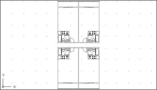
With the tools you’ve learned about so far, you’ve quickly and accurately set up a fairly good portion of the floor plan. Continue with the next few steps to “rough in” the main components of the floor:
1. Click the Zoom button from the status bar and then type E↵, or type Z↵ E↵ to get a view of the four plans. The Extents option forces the entire drawing to fill the screen at the center of the display area. Your drawing will look like Figure 7-2.
If you happen to insert a block in the wrong coordinate location, you can use the Properties Inspector palette to change the insertion point for the block.
2. Copy the four units to the right at a distance of 28´-10˝ (878 cm for metric users), which is the width of two units from center line to center line of the walls.
Figure 7-2:The unit plan, duplicated four times
3. Insert the lobby.dwg file at coordinate 89´-1˝,76´-1˝ (the Lobby-metric.dwg file at coordinate 2713,2318 for metric users).
4. Copy all the unit plans to the right 74´-5˝ (2267 cm for metric users), the width of four units plus the width of the lobby.
5. Click the Zoom button from the status bar and then type A↵, or type Z↵ A↵ to view the entire drawing, which should look like Figure 7-3.
Figure 7-3:The Plan drawing

6. Choose File Save on the menu bar, or press F-S to save this Plan.dwg file to disk.
Taking Control of the AutoCAD Display
By now, you should be familiar with the Pan and Zoom functions in AutoCAD. Many other tools can also help you get around in your drawing. In the following sections, you’ll get a closer look at the ways you can view your drawing.
Understanding Regeneration and Redrawing
AutoCAD uses two commands for refreshing your drawing display: Regen (drawing regeneration) and Redraw. Each command serves a particular purpose, although it may not be clear to a new user.
To better understand the difference between Regen and Redraw, it helps to know that AutoCAD stores drawing data in two ways:
- In a database of highly accurate coordinate information that is part of the properties of objects in your drawing
- In a simplified database used just for the display of the objects in your drawing
As you draw, AutoCAD starts to build an accurate, core database of objects and their properties. At the same time, it creates a simpler database that it uses just to display the drawing quickly. AutoCAD uses this second database to allow quick manipulation of the display of your drawing. For the purposes of this discussion, I’ll call this simplified database the virtual display because it’s like a computer model of the overall display of your drawing. This virtual display is in turn used as the basis for what is shown in the drawing area. When you issue a Redraw command, you’re telling AutoCAD to reread this virtual display data and display that information in the drawing area. A Regen command, on the other hand, tells AutoCAD to rebuild the virtual display based on information from the core drawing database.
You may notice that the Pan Realtime and Zoom Realtime commands don’t work beyond a certain area in the display. When you reach a point where these commands seem to stop working, you’ve come to the limits of the virtual display data. To go beyond these limits, AutoCAD must rebuild the virtual display data from the core data; in other words, it must regenerate the drawing. You can usually do this by zooming out to the extents of the drawing.
Sometimes, when you zoom in to a drawing, arcs and circles may appear to be faceted instead of smooth curves. This faceting is the result of AutoCAD’s virtual display simplifying curves to conserve memory. You can force AutoCAD to display smoother curves by typing RE↵, which is the shortcut for the Regen command.
Controlling Display Smoothness with Viewres
As you work in AutoCAD, you may notice that linetypes sometimes appear continuous even when they’re supposed to be dotted or dashed. You may also notice that arcs and circles occasionally appear to be segmented lines although they’re always plotted as smooth curves. A command called Viewres controls how smoothly linetypes, arcs, and circles are displayed in an enlarged view. The lower the Viewres value, the fewer the segments and the faster the redraw and regeneration. However, a low Viewres value causes noncontinuous linetypes, such as dashes or center lines, to appear as though they’re continuous, especially in drawings that cover very large areas (for example, civil site plans).
Finding a Viewres value that best suits the type of work you do will take some experimentation. The default Viewres setting is 1000. You can try increasing the value to improve the smoothness of arcs and see if a higher value works for you. Enter VIEWRES↵ at the Command prompt to change the value. If you work with complex drawings, you may want to keep the value at 1000; then when you zoom in close to a view, use the Regen command to display smooth arcs and complete linetypes.
Creating Multiple Views
So far, you’ve looked at ways to help you get around in your drawing while using a single view window. You can also set up multiple views of your drawing, called viewports. With viewports, you can display more than one view of your drawing at one time in the AutoCAD drawing area. For example, one viewport can display a close-up of the bathroom, another viewport can display the overall plan view, and yet another can display the unit plan.
When viewports are combined with AutoCAD’s Paper Space feature, you can print multiple views of your drawing. Paper Space is a display mode that lets you paste up multiple views of a drawing, much like a page-layout program. To find out more about viewports and Paper Space, see Chapter 14, “Advanced Editing and Organizing.”
Saving Views
Another way to control your views is by saving them. You might think of saving views as a way of creating a bookmark or a placeholder in your drawing.
For example, a few walls in the Plan drawing aren’t complete. To add the lines, you’ll need to zoom in to the areas that need work, but these areas are spread out over the drawing. AutoCAD lets you save views of the areas you want to work on and then jump from saved view to saved view. This technique is especially helpful when you know you’ll often want to return to a specific area of your drawing.
You’ll see how to save and recall views in the following set of exercises. We’ll save a view of the elevator lobby:
1. Click the Zoom button from the status bar and then type W↵, or type Z↵ W↵ and put a window around the elevator lobby, as shown in Figure 7-4.
2. Type V↵ at the command line.
Figure 7-4:Select this area for your saved view.

Managing Saved Views
In the View options on the command line, you can call up an existing view (Restore), create a new view (Save), or get detailed information about a view. You can also select from a set of predefined views that include orthographic and isometric views of 3D objects. You’ll learn more about these options in Chapter 19, “Creating 3D Drawings.”
3. Type S↵ at the command line.
4. At the Enter view name to save: prompt, type Elevator Lobby↵. The view is saved.
Let’s see how to recall the view that you’ve saved.
1. Click the Zoom button from the status bar and then type A↵, or type Z↵ A↵ to view the entire plan.
2. Type V↵ at the command line.
3. Type R↵ to initiate the restore subfunction.
4. At the Enter view name to restore: prompt, type Elevator Lobby↵.
Your view changes to a close-up of the area you selected earlier.
If you need to make adjustments to a view after you’ve created it, you can do so by following these steps: Zoom to the view you want to save, and type V↵ and then S↵. Type the name exactly as you did before. Allow the new view to overwrite the old view.
5. Save the Plan file to disk.
Repeat the Last Command
Remember that when no command is active, you can right-click the command line and then select one of the recent commands at the top of the shortcut menu to repeat it. You can also right-click the drawing area when AutoCAD is idle and repeat the last command.
Understanding the Frozen Layer Option
As mentioned earlier, you may want to turn off certain layers to print a drawing containing only selected layers. But even when layers are turned off, AutoCAD still takes the time to redraw and regenerate them. The Layers palette offers the Freeze option; this acts like the Off option, except that Freeze causes AutoCAD to ignore frozen layers when redrawing and regenerating a drawing. By freezing layers that aren’t needed for reference or editing, you can reduce the time AutoCAD takes to perform regens. This can be helpful in large, multi-megabyte files.
Be aware, however, that the Freeze option affects blocks in an unusual way. Try the following exercise to see firsthand how the Freeze option makes entire blocks disappear:
1. Close the Plan file, and open the 07b-plan.dwg file from the book’s companion website. Metric users should open 07b-plan-metric.dwg. This file is similar to the Plan file you created but with a few additional walls and stairs added to finish off the exterior.
2. In the Layers palette, set the current layer to 0.
3. Click the on/off icon in the Plan1 layer listing to turn off that layer. Nothing changes in your drawing. Even though you turned off the Plan1 layer, the layer on which the unit blocks were inserted, the unit blocks remain visible.
4. Right-click in the layer list, choose Select All from the shortcut menu, and then click an on/off icon (not the one you clicked in step 3). You see a message warning you that the current layer will be turned off. Click Turn The Current Layer Off. Now everything is turned off, including objects contained in the unit blocks.
5. Click the on/off icon next to any layer to turn all of the layers back on.
6. Right-click in the layer list, and choose Clear All from the shortcut menu. All layers are now deselected.
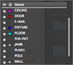
7. Click the Plan1 layer’s Freeze/Thaw column. (You can’t freeze the current layer.) A gray snowflake appears, indicating that the layer is now frozen (Figure 7-5). Only the unit blocks disappear.
Figure 7-5:Freezing the Plan1 layer

Even though none of the objects in the unit blocks were drawn on the Plan1 layer, the entire contents of the blocks assigned to the Plan1 layer are frozen when Plan1 is frozen.
You don’t really need the Plan1 layer frozen. You froze it to see the effects of Freeze on blocks. Do the following to thaw the Plan1 layer:
1. Thaw layer Plan1 by going back to the Layers palette and clicking the snowflake icon in the Plan1 layer listing.
2. Turn off the Ceiling layer.
The previous exercise showed the effect of freezing on blocks. When a block’s layer is frozen, the entire block is made invisible regardless of the layer assignments of the objects contained in the block.
Keep in mind that when blocks are on layers that aren’t frozen, the individual objects that are part of the block are still affected by the status of the layer to which they’re assigned. This means that if some objects in a block are on a layer called Wall and the Wall layer is turned off or frozen, then those objects become invisible. Objects within the block that aren’t on the layer that is off or frozen remain visible.
Using Hatch Patterns in Your Drawings
To help communicate your ideas to others, you’ll want to add graphic elements that represent types of materials, special regions, or textures. AutoCAD provides hatch patterns for quickly placing a texture over an area of your drawing. In the following sections, you’ll add a hatch pattern to the floor of the studio apartment unit, thereby instantly enhancing the appearance of one drawing. In the process, you’ll learn how to update all the units in the overall floor plan quickly to reflect the changes in the unit.
Placing a Hatch Pattern in a Specific Area
It’s always a good idea to provide a separate layer for hatch patterns. By doing so, you can turn them off if you need to. For example, the floor paving pattern might be displayed in one drawing but be turned off in another so it won’t distract from other information.
In the following exercises, you’ll set up a layer for a hatch pattern representing floor tile and then add that pattern to your drawing. This will give you the opportunity to learn the different methods of creating and controlling hatch patterns.
Follow these steps to set up the layer:
1. Open the 07a-unit.dwg file. Metric users should open 07a-unit-metric.dwg. These files are similar to the Unit drawing you created in earlier chapters and are used to create the overall plan in the 07b-plan and 07b-plan-metric files. Remember that you also still have the 07b-plan or 07b-plan-metric file open.
2. Zoom in to the bathroom and kitchen area.
3. Create a new layer called Flr-pat.
4. Make Flr-pat the current layer.
Now that you’ve set up the layer for the hatch pattern, you can place the pattern in the drawing:
1. Click the Hatch tool on the Tool Sets palette, or type H↵. The Hatch And Gradient dialog box appears (Figure 7-6).
2. In the Type pop-up menu (see Figure 7-6), select User Defined. The User Defined option lets you define a simple crosshatch pattern by specifying the line spacing of the hatch and whether it’s a single- or double-hatch pattern.
3. Highlight the value in the Spacing input box, and enter 6 (metric users should enter 15). This tells AutoCAD you want the hatch’s line spacing to be 6 inches, or 15 cm. Leave the Angle value at 0 because you want the pattern to be aligned with the bathroom.
Figure 7-6:The Hatch And Gradient dialog box

4. Click the Double check box. This tells AutoCAD that you want the hatch pattern to run both vertically and horizontally.
5. Click the Add: Pick Points button. The Hatch And Gradient dialog box disappears. Back in your drawing, hover the cursor over different parts of the bathroom layout but don’t click anything. You will see a preview of your hatch pattern appear in each area that you hover over.
6. Click inside the area representing the bathroom floor. The floor area is now highlighted. Notice that the area inside the door swing is not highlighted. This is because the door swing area is not a contiguous part of the floor.
Hatching around Text
If you have text in the hatch boundary, AutoCAD will avoid hatching over it unless the Ignore option is selected in the Island Display Style options of the Advanced Hatch settings. See the section “Controlling Hatch Behavior” later in this chapter for more on the Ignore setting.
7. Click inside the door swing to place the hatch pattern.
8. Press ↵ twice to exit the Hatch command.
As you saw from the exercise, AutoCAD gives you a preview of your hatch pattern before you place it in the drawing. In the previous steps, you set up the hatch pattern first by selecting the User Defined option, but you can reverse the order if you like. You can click in the areas you want to hatch first and then select a pattern; then you can adjust the scale and apply other hatch options.
Inheriting Hatch Properties
Say you want to add a hatch pattern that you’ve previously inserted in another part of the drawing. With the Inherit Properties button in the Hatch And Gradient dialog box, you can select a previously created hatch pattern as a prototype for the current hatch pattern. However, this feature doesn’t work with exploded hatch patterns.
Adding Predefined Hatch Patterns
In the previous exercise, you used the User Defined option to create a simple crosshatch pattern. You also have a number of predefined hatch patterns to choose from. You can also find other hatch patterns on the Internet, and if you can’t find the pattern you want, you can create your own (see Bonus Chapter 2, “Customizing Toolsets, Menus, Linetypes, and Hatch Patterns,” found on the book’s companion website).
Try the following exercise to see how you can add one of the predefined patterns available in AutoCAD:
1. Pan your view so that you can see the area below the kitchenette. Using the Rectangle tool in the Tool Sets palette, draw the 3´-0˝--8´-0˝ outline of the floor tile area, as shown in Figure 7-7. Metric users should create a rectangle that is 91 cm 228 cm. You can also use a closed polyline.
Figure 7-7:The area below the kitchen, showing the outline of the floor tile area

2. Click the Hatch tool in the Tool Sets palette.
3. In the Hatch And Gradient dialog box, change the Type from User Defined to Predefined.
4. Select the ellipsis button next to Pattern, and the Hatch Pattern Palette appears (Figure 7-8). This list has a scroll bar to the right that lets you view additional patterns.
5. Scroll down the list and locate and select AR-PARQ1 (Figure 7-8).
Figure 7-8:The Hatch Pattern Palette

6. Click OK to dismiss the Hatch Pattern Palette.
7. Click the Add: Pick Points button and then click inside the rectangle you just drew.
8. Press ↵ twice to exit the Hatch command.
The predefined patterns with the AR prefix are architectural patterns that are drawn to full scale. In general, you should leave their Scale setting at 1. You can adjust the scale after you place the hatch pattern by using the Properties Inspector palette, as described later in this chapter.
Adding Solid Fills
With Type set to Predefined, you can select Solid from the Pattern pop-up menu in the Hatch And Gradient dialog box. The Hatch Color pop-up menu lets you set the color of your solid fill.
Positioning Hatch Patterns Accurately
In the previous hatch pattern exercise, you may have noticed that the hatch pattern fit neatly into the 8´ 3´ rectangle. The AR-PARQ1 pattern is made up of 1´ squares so they will fit exactly in an area that is of even 1´ increments. In addition, AutoCAD places the origin of the pattern in the bottom-left corner of the area being filled by default.
You won’t always have a hatch pattern fit so easily in an area. If you’ve ever laid tile in a bathroom, for example, you know that you have to carefully select the starting point for your tiles to get them to fit in an area with pleasing results. If you need to fine-tune the position of a hatch pattern within an enclosed area, you can do so by first clicking the Specified Origin radio button in the Hatch And Gradient dialog. This will enable other options below, including the Click To Set New Origin button.
Click To Set New Origin lets you specify an origin point for your hatch pattern. You can also use the HPORIGIN system variable to accomplish this, or click the Default To Boundary Extents check box to select from a set of predefined origin locations. These locations are bottom left, bottom right, top left, top right, and center. The Use Current Origin option refers to the X,Y origin of the drawing.
If you are hatching an irregular shape, these origin locations are applied to the boundary extents of the shape. An imaginary rectangle represents the outermost boundary, or the boundary extents of the shape, as shown in Figure 7-9.
Figure 7-9:The origin options shown in relation to the boundary extents of an irregular shape

The Store As Default Origin option lets you save your selected origin as the default origin for future hatch patterns in the current drawing.
Now that you’ve learned how to add a hatch pattern, let’s continue with a look at how your newly edited plan can be used. In the next exercise, you’ll use this updated 07a-unit file to update all the units in the Plan file.
Updating a Block from an External File
As you progress through a design project, you make countless revisions. With traditional drafting methods, revising a drawing such as the studio apartment floor plan takes a good deal of time. If you change the bathroom layout, for example, you have to erase every occurrence of the bathroom and redraw it 16 times. With AutoCAD, on the other hand, revising this drawing can be a quick operation. You can update the studio unit you just modified throughout the overall plan drawing by replacing the current Unit block with the updated Unit file. AutoCAD can update all occurrences of the Unit block. The following exercise shows how this is accomplished.
For this exercise, remember that the blocks representing the units in the 07b-plan and 07b-plan-metric files are named 07a-unit and 07a-unit-metric:
1. Make sure you’ve saved the 07a-unit (07a-unit-metric for metric users) file with the changes, and then return to the 07b-plan file that is still open.
You Can’t Update Exploded Blocks
Exploded blocks won’t be updated when you update blocks from an external file. If you plan to use this method to update parts of a drawing, don’t explode the blocks you plan to update. See Chapter 4, “Organizing Objects with Blocks and Groups.”
2. Click the Insert tool on the Tool Sets palette.
3. Click the Browse button. In the Select Drawing File dialog box, double-click the 07a-unit filename (07a-unit-metric for metric users).
4. Click Insert in the Insert Block dialog box. A warning message tells you that a block already exists with the same name as the file. You can cancel the operation or redefine the block in the current drawing.
5. Click Redefine Block. The drawing regenerates.
6. At the Specify insertion point or [Basepoint/Scale/X/Y/Z/Rotate]: prompt, press the Esc key. You do this because you don’t want to insert the Unit file into your drawing; you’re just using the Insert feature to update an existing block.
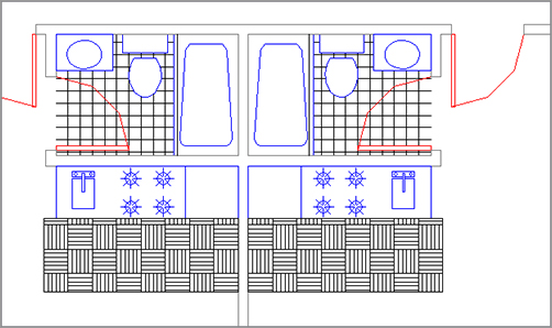
7. Zoom in to one of the units. The floor tile appears in all the units as you drew it in the Unit file (see Figure 7-10).
Figure 7-10:The Plan drawing with the tile pattern
Nested blocks must be updated independently of the parent block. For example, if you modified the Toilet block while editing the 07a-unit file and then updated the 07a-unit drawing in the 07b-plan file, the old Toilet block wouldn’t be updated. Even though the toilet is part of the 07a-unit file, it’s still a unique, independent block in the Plan file, and AutoCAD won’t modify it unless specifically instructed to do so. In this situation, you must edit the original Toilet block and then update it in both the Plan and Unit files.
Replacing Blocks
If you want to replace one block with another in the current file, type –Insert↵. (Don’t forget the minus sign in front of Insert.) At the Block name: prompt, enter the block name followed by an equal sign (=), and then enter the name of the new block or the filename. Don’t include spaces between the name and the equal sign.
Also, block references and layer settings of the current file take priority over those of the imported file. For example, if a file to be imported has layers of the same name as the layers in the current file but those layers have color and linetype assignments that are different from the current file’s, the current file’s layer color and linetype assignments determine those of the imported file. This doesn’t mean, however, that the imported file on disk is changed; only the inserted drawing is affected.
Substituting Blocks
In the preceding example, you updated a block in your Plan file by using the Browse button in the Insert Block dialog box. In that exercise, the block name and the filename were the same. You can also replace a block with another block or a file of a different name. Here’s how to do that:
1. Open the Insert Block dialog box.
2. Click the Browse button next to the Name input box, locate and select the file you want to use as a substitute, and then click Open to return to the Insert Block dialog box.
3. Change the name in the Name input box to the name of the block you want replaced.
4. Click Insert. A warning message appears, telling you that a block with this name already exists. Click Redefine Block to proceed with the block substitution.
You can use this method of replacing blocks if you want to see how changing one element of your project can change your design. You might, for example, draw three different apartment unit plans and give each plan a unique name. You could then generate and print three apartment building designs in a fraction of the time it would take you to do so by hand.
Block substitution can also reduce a drawing’s complexity and accelerate regenerations. To substitute blocks, you temporarily replace large, complex blocks with schematic versions. For example, you might replace the Unit block in the Plan drawing with another drawing that contains just a single-line representation of the walls and bathroom fixtures. You would still have the wall lines for reference when inserting other symbols or adding mechanical or electrical information, but the drawing would regenerate much faster. When you did the final print, you would reinsert the original Unit block showing every detail.
Changing the Hatch Area
You may have noticed the Associative option in the Hatch And Gradient dialog box. When this check box is selected, AutoCAD creates an associative hatch pattern. Associative hatches adjust their shapes to any changes in their associated boundary, hence the name (see the section “Controlling Hatch Behavior” later this chapter). The following exercise demonstrates how this works.
Suppose you want to enlarge the tiled area of the kitchen by one tile. Here’s how it’s done:
1. Choose Window 07a-Unit.dwg file from the menu bar.
2. Click the outline border of the hatch pattern you created earlier. Notice the grips that appear around the hatch-pattern area.
3. Click the grip in the bottom center of the hatch area.
Selecting Hatch Grips
If the boundary of the hatch pattern consists of line segments, you can use a crossing window or polygon-crossing window to select the corner grips of the hatch pattern.
4. Enter @12<–90↵↵ (@30<–90 for metric users) to widen the hatch pattern by 1´, or 30 cm for metric users. The hatch pattern adjusts to the new size of the hatch boundary.
5. Press the Esc key to clear any grip selections.
6. Choose File Save from the menu bar or press F-S to save the Unit file.
7. Return to the Plan file using the menu bar, and repeat the steps in the section “Updating a Block from an External File” earlier in this chapter to update the units again.
The Associative feature of hatch patterns can save time when you need to modify your drawing, but you need to be aware of its limitations. A hatch pattern can lose its associativity when you do any of the following:
- Erase or explode a hatch boundary
- Erase or explode a block that forms part of the boundary
- Move a hatch pattern away from its boundary
These situations frequently arise when you edit an unfamiliar drawing. Often, boundary objects are placed on a layer that is off or frozen, so the boundary objects aren’t visible. Also, the hatch pattern might be on a layer that is turned off and you proceed to edit the file not knowing that a hatch pattern exists. When you encounter such a file, take a moment to check for hatch boundaries so you can deal with them properly.
Modifying a Hatch Pattern
Like everything else in a project, a hatch pattern may eventually need to be changed in some way. Hatch patterns are like blocks in that they act like single objects. You can explode a hatch pattern to edit its individual lines. The Properties Inspector palette contains most of the settings you’ll need to make changes to your hatch patterns. But the most direct way to edit a hatch pattern is to use the Hatch Edit dialog box.
Editing Hatch Patterns from the Hatch Edit Dialog Box
Follow these steps to modify a hatch pattern by using the Hatch Edit dialog box (Figure 7-11):
1. Return to the Unit drawing using the menu bar.
2. Press the Esc key to clear any grip selections that may be active from earlier exercises.
3. Double-click the hatch pattern in the kitchen to open the Hatch Edit dialog box. It’s the same as the Hatch And Gradient dialog box.
4. In the Pattern pop-up menu, select the pattern named AR-BRSTD. It’s the pattern that looks like a brick wall.
5. Click OK. The AR-BRSTD pattern appears in place of the original parquet pattern.
6. Exit and save your file.
Figure 7-11:The Hatch Edit dialog box
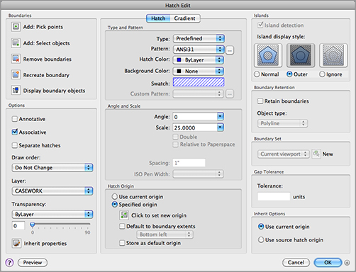
In this exercise, you were able to change the hatch just by double-clicking it. Although you changed only the pattern type, other options are available. You can, for example, change a predefined pattern to a user-defined one by selecting User Defined from the Type pop-up menu in the Hatch Edit dialog box.
You can then enter angle and scale values for your hatch pattern in the options provided in the Angle and Scale group in the Hatch Edit dialog box.

The other items in the Hatch Edit dialog box are duplicates of the options in the Hatch And Gradient dialog box. They let you modify the individual properties of the selected hatch pattern. The upcoming section, “Understanding the Boundary Hatch Options,” describes these other properties in detail.
Take a Break
If you’re working through the tutorial in this chapter, this would be a good place to take a break or stop. You can pick up the next exercise in the section “Attaching a Drawing as an External Reference” at another time.
Understanding the Boundary Hatch Options
The Hatch And Gradient dialog box and Hatch Edit dialog box offer many other options that you didn’t explore in the previous exercises. For example, instead of clicking in the area to be hatched, you can select the objects that bound the area you want to hatch by clicking the Add: Select Objects button in the Boundaries group. You can use the Add: Select Objects button to add boundaries to existing hatch patterns as well.
Controlling Boundaries with the Boundaries Group
The previous exercises in this chapter have just touched on the options in the Boundaries group of the Hatch and Gradient dialog box. Options in the Boundaries group are Add: Pick Points, Add: Select Objects, Remove Boundaries, Recreate Boundary, and View Selections.
Add: Pick Points Lets you select an area to be hatched based on a closed boundary.
Add: Select Objects Lets you select objects to define a hatch boundary.
Remove Boundaries Lets you remove a bounded area, or island, in the area to be hatched. An example is the toilet seat in the bathroom. This option is available only when you select a hatch area by using the Add: Pick Points option and an island has been detected.
Recreate Boundary Draws a region or polyline around the current hatch pattern. You’re then prompted to choose between a region or a polyline and to specify whether to reassociate the pattern with the re-created boundary. (See the Associative Hatch Patterns sidebar, discussed later in this chapter.)
View Selections After you have selected boundaries to hatch, clicking this tool will temporarily close the Hatch And Gradient dialog box and highlight the areas that you have selected.
Fine-Tuning the Boundary Behavior
The Boundary Hatch feature is view dependent; that is, it locates boundaries based on what is visible in the current view. If the current view contains a lot of graphic data, AutoCAD can have difficulty or be slow in finding a boundary. If you run into this problem, or if you want to single out a specific object for a point selection boundary, you can use the Boundary Set options found in the expanded Hatch And Gradient dialog box to further limit the area that AutoCAD uses to locate hatch boundaries:
View Selections in the Boundaries Group This highlights the objects that have been selected as the hatch boundary by AutoCAD.
Retain Boundary Objects under the Boundary Retention Group This retains outlines used to create the hatch pattern. This can be helpful if you want to duplicate the shape of the boundary for other purposes. Typically this is set to Don’t Retain Boundaries, but you can use two other settings: Retain Boundaries – Polyline and Retain Boundaries – Region. The Retain Boundaries – Polyline option retains the boundaries as polylines. The Retain Boundaries – Regions option retains the boundaries as regions.
Hatch Boundaries without the Hatch Pattern
The Boundary command creates a polyline outline or region in a selected area. It works much like the Retain Boundaries – Polyline option but doesn’t add a hatch pattern.
Select New Boundary Set under the Boundary Set Group This lets you select the objects you want AutoCAD to use to determine the hatch boundary instead of searching the entire view. The screen clears and lets you select objects. This option discards previous boundary sets. It’s useful for hatching areas in a drawing that contains many objects that you don’t want to include in the hatch boundary.
Use Current Viewport under the Boundary Set Group This uses the current viewport extents to define the boundary set.
The Boundary Set options are designed to give you more control over the way a point selection boundary is created. These options have no effect when you use the Add: Select Objects button to select specific objects for the hatch boundary.
Boundary Retention
The Hatch command can also create an outline of the hatch area by using one of two objects: 2D regions, which are like 2D planes, or polyline outlines. Hatch creates such a polyline boundary temporarily to establish the hatch area. These boundaries are automatically removed after the hatch pattern is inserted. If you want to retain the boundaries in the drawing, make sure the Retain Boundaries – Polyline option is selected. Retaining the boundary can be useful if you know you’ll be hatching the area more than once or if you’re hatching a fairly complex area.
Retaining a hatch boundary is useful if you want to know the hatched area’s dimensions in square inches or feet because you can find the area of a closed polyline by using the List command. See Chapter 2, “Creating Your First Drawing,” for more on the List command.
Controlling Hatch Behavior
The Hatch And Gradient dialog box offers a set of tools that control some additional features of the Hatch command. These features affect the way a hatch pattern fills a boundary area as well as how it behaves when the drawing is edited. Note that the Gap Tolerance and Island Detection options are on the expanded dialog box. You can find these by clicking on the disclosure triangle located on the lower-right side of the dialog box. The following gives you a brief description of the options in the Options, Islands, Gap Tolerance, and Inherit Options groups:
Annotative Allows the hatch pattern to adjust to different scale views of your drawing. With this option turned on, a hatch pattern’s size or spacing adjusts to the annotation scale of a viewport layout or Model Space view. See Chapter 4 for more on the annotation scale.
Annotative Hatch Patterns
In Chapter 4, you learned about a feature called the annotation scale. With this feature, you can assign several scales to certain types of objects and AutoCAD displays the object to the proper scale of the drawing. You can take advantage of this feature to allow hatch patterns to adjust their spacing or pattern size to the scale of your drawing. The Annotative option in the Hatch And Gradient dialog box turns on the annotation scale feature for hatch patterns. Once this feature is turned on for a hatch pattern, you can set up the drawing scales that you want to apply to the hatch pattern using the same methods described for blocks in Chapter 4.
Associative Allows the hatch pattern to adjust to changes in its boundary. With this option turned on, any changes to the associated boundary of a hatch pattern cause the hatch pattern to flow with the changes in the boundary.
Create Separate Hatches Creates separate and distinct hatches if you select several enclosed areas while selecting hatch areas. With this option off, separate hatch areas behave as a single hatch pattern.
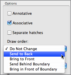
Draw Order Allows you to specify whether the hatch pattern appears on top of or underneath its boundary. This is useful when the boundary is of a different color or shade and must read clearly or when the hatch pattern must cover the boundary. The options in this list are self-explanatory and are Do Not Assign, Send To Back, Bring To Front, Send Behind Boundary, and Bring In Front Of Boundary. See “Overlapping Objects with Draw Order” later in this chapter.
Layer Allows you to select a layer that the hatch will be drawn on. By default, the hatch will be drawn on the current layer.
Transparency Contains four options for transparency:
Use Current Will use the current object transparency setting.
ByLayer Will use the current layer transparency setting.
ByBlock If the hatch object is contained in a block, it will use the current block transparency setting.
Specify Value You can choose a transparency value by either entering it into the text box or using the slider.
Inherit Properties The Inherit Properties icon allows you to select a hatch on the drawing area. All properties associated with the selected hatch will be passed to the new hatch area.
Islands Detection Controls how islands within a hatch area are treated. Islands are enclosed areas that are completely inside a hatch boundary. When the Island Detection checkbox is selected, there are three options in this list:
Normal Island Detection This causes the hatch pattern to alternate between nested boundaries. The outer boundary is hatched; if there is a closed object within the boundary, it isn’t hatched. If another closed object is inside the first closed object, that object is hatched. This is the default setting.
Outer Island Detection This applies the hatch pattern to an area defined by the outermost boundary and a closed object within that boundary. Any boundaries nested in that closed object are ignored.
Ignore Island Detection This supplies the hatch pattern to the entire area within the outermost boundary, ignoring any nested boundaries.
Gap Tolerance This group lets you hatch an area that isn’t completely enclosed. The Gap Tolerance value sets the maximum gap size in an area you want to hatch. You can use a value from 0 to 5000.
Inherit Options This group allows you to use an existing hatch pattern when inserting additional hatch patterns into a drawing. Select the Use Current Origin button and then select the hatch on the drawing screen that you wish to use. All properties of the selected hatch will be copied to the newly created hatch.
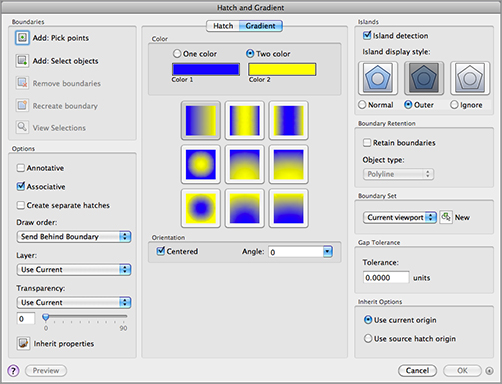
Using Gradient Shading
We have discussed the Solid option in the Pattern pop-up menu. The solid hatch pattern lets you apply a solid color instead of a pattern to a bounded area. AutoCAD also offers a set of gradient patterns that let you apply a color gradient to an area.
You can apply a gradient to an area by using the Gradient tab on the Hatch And Gradient dialog box. When you select the Gradient tab, you’ll see a slight change. The Type And Pattern group changes to show a set of different gradient patterns. The Origin group also changes to the Orientation group (Figure 7-12).
Figure 7-12:The Gradient tab of the Hatch And Gradient dialog box
Choosing a Gradient Color
Instead of offering hatch patterns, the Gradient tab offers a variety of gradient patterns. If you wish to change a color, you can click the color swatch to open the Color Palette dialog box. This dialog box lets you choose from Index, True Color, or Color Books colors (Figure 7-13).
Figure 7-13:The Color Palette dialog box

Choosing between a Single Color and Two Colors
You can choose a gradient that transitions between shades of a single color by clicking the One Color radio button. This turns on the Shade And Tint slider and disables the Color 2 swatch. When you select the Two Color radio button, the Shade And Tint slider is disabled and the Color 2 swatch is displayed.
Selecting Gradient Patterns
As mentioned earlier, you can choose from a set of gradient patterns from the Color option. The Angle pop-up menu gives you further control over the gradient pattern by allowing you to rotate the angle of the pattern. The pop-up menu is set to 15-degree increments; however, you can type in a value in the text box. The Centered option places the center of the gradient at the center of the area selected for the pattern. This option is a toggle that is either on or off.
To place a gradient pattern, select a set of objects or a point in a bounded area, just as you would for a hatch pattern.
Tips for Using Hatch
Here are a few tips on using the Hatch feature:
- Watch out for boundary areas that are part of a large block. AutoCAD examines the entire block when defining boundaries. This can take time if the block is large. Use the Select New Boundary Set option in the Boundary Set option group to focus in on the set of objects you want AutoCAD to use for your hatch boundary. If you desire, you can turn off the preview by using the HPQUICKPREVIEW system variable. ON turns the preview on, and OFF turns it off. You may want to turn this off if you are doing a lot of hatching in large areas.
- The Hatch feature is view dependent; that is, it locates boundaries based on what is visible in the current view. To ensure that AutoCAD finds every detail, zoom in to the area to be hatched.
- If the area to be hatched is large yet requires fine detail, first outline the hatch area by using a polyline. (See Chapter 17, “Drawing Curves,” for more on polylines.) Then use the Add: Select Objects option in the Boundaries group to select the polyline boundary manually instead of depending on Hatch to find the boundary for you.
- Consider turning off layers that might interfere with AutoCAD’s ability to find a boundary.
- Hatch works on nested blocks as long as the nested block entities are parallel to the current UCS.
Space Planning and Hatch Patterns
Suppose you’re working on a plan in which you’re constantly repositioning equipment and furniture or you’re in the process of designing the floor covering. You might be a little hesitant to place a hatch pattern on the floor because you don’t want to have to rehatch the area each time you move a piece of equipment or change the flooring. You have two options in this situation: You can use Hatch’s associative capabilities to include the furnishings in the boundary set, or you can use the Draw Order feature.
Using Associative Hatch
Associative Hatch is the most straightforward method. Make sure the Associative option is selected in the Options group, and include your equipment or furniture in the boundary set. You can do this by using the Add: Select Objects option in the Boundaries options.
After the hatch pattern is in place, it automatically adjusts to its new location when you move the furnishings in your drawing. One drawback, however, is that AutoCAD attempts to hatch the interior of your furnishings if they cross the outer boundary of the hatch pattern. Also, if any boundary objects are erased or exploded, the hatch pattern no longer follows the location of your furnishings. To avoid these problems, you can use the method described in the next section.
Overlapping Objects with Draw Order
The Draw Order feature lets you determine how objects overlap. In the space-planning example, you can create furniture by using a solid hatch to indicate horizontal surfaces (see Figure 7-14).
Figure 7-14:Using Draw Order to create an overlapping effect over a hatch pattern
How to Match a Hatch Pattern and Other Properties Quickly
Another tool to help you edit hatch patterns is Match Properties, which is similar to Format Painter in the Microsoft Office system. This tool lets you change an existing hatch pattern to match another existing hatch pattern. Here’s how to use it:
1. Type MA↵.
2. Click the source hatch pattern you want to copy.
3. Click the target hatch pattern you want to change. The target pattern changes to match the source pattern.
The Match Properties tool transfers other properties as well, such as layer, color, and linetype settings. You can select the properties that are transferred by opening the Match Properties Settings dialog box.

To open this dialog box, type S↵ after selecting the source object in step 2, or right-click and choose Settings from the shortcut menu. You can then select the properties you want to transfer from the options shown. All the properties are selected by default. You can also transfer text and dimension style settings. You’ll learn more about text and dimension styles in Chapter 9, “Adding Text to Drawings,” and Chapter 11, “Using Dimensions.”
You can then place the furniture on top of a floor-covering pattern and the pattern will be covered and hidden by the furniture. Here’s how to do that. (These steps aren’t part of the regular exercises of this chapter. They’re shown here as general guidelines when you need to use the Draw Order feature.)
1. Draw the equipment outline, and make sure the outline is a closed polygon.
2. Start the Hatch tool described earlier in this chapter and place a solid hatch pattern inside the equipment outline.
3. In the Hatch And Gradient dialog box, make sure Send To Back is selected in the Draw Order pop-up menu.
4. Turn the outline and solid hatch into a block, or use the Group command to group them.
5. Move your equipment drawing into place over the floor pattern.
6. Double-click on the floor hatch pattern, and then in the Hatch Edit dialog box, select Send To Back from the Draw Order pop-up menu. (See the middle panel in Figure 7-14.)
After you take these steps, the equipment will appear to rest on top of the pattern. (See the bottom panel in Figure 7-14.) You can also change the display order of objects relative to other objects in the drawing using the Draw Order options in the right-click menu.
The Draw Order options are all part of the Draworder command. As an alternative to the menus, you can type DR↵ at the Command prompt, select an object, and then enter an option at the prompt:
Enter object ordering option
[Above objects/Under objects/Front/Back] <Back>:
For example, the equivalent of choosing the Send To Back tool from the Draw Order option is entering DR↵ B↵. You can also select the object you want to edit, right-click, and then choose Draw Order from the shortcut menu.
AutoCAD allows you to import drawings in a way that keeps the imported drawing independent from the current one. A drawing imported in this way is called an external reference (Xref). Unlike drawings that have been imported as blocks, Xref files don’t become part of the drawing’s database. Instead, they’re loaded along with the current file at startup time. It’s as if AutoCAD were opening several drawings at once: the currently active file you specify when you start AutoCAD and any file inserted as an Xref.
If you keep Xref files independent from the current file, any changes you make to the Xref automatically appear in the current file. You don’t have to update the Xref file manually as you do blocks. For example, if you use an Xref to insert the Unit file into the Plan file and you later make changes to the Unit file, you will see the new version of the Unit file in place of the old one the next time you open the Plan file. If the Plan file was still open while edits were made, AutoCAD will notify you that a change has been made to an Xref.
Blocks and Xrefs Can’t Have the Same Name
You can’t use an Xref file if the file has the same name as a block in the current drawing. If this situation occurs but you still need to use the file as an Xref, you can rename the block of the same name by using the Rename command. You can also use Rename to change the name of various objects and named elements.
Another advantage of Xref files is that because they don’t become part of a drawing’s database, drawing size is kept to a minimum. This results in more efficient use of your hard disk space.
Xref files, like blocks, can be edited only by using special tools. You can, however, use osnaps to snap to a location in an Xref file, or you can freeze or turn off the Xref file’s insertion layer to make it invisible.
Attaching a Drawing as an External Reference
The next exercise shows how to use an Xref in place of an inserted block to construct the studio apartment building. You’ll first create a new unit file by copying the old one. Then you’ll bring a new feature, the Reference Manager palette, to the screen. Follow these steps to create the new file:
1. Choose Window 07a-unit.dwg from the menu bar to return to the 07a-unit file.
2. Choose File Save As from the menu bar or press ![]() -F-S to save it under the name unitxref.dwg, and then close the unitxref.dwg file. This will make a copy of the 07a-unit.dwg file for the following steps. Or, if you prefer, you can use the unitxref.dwg file for the following steps.
-F-S to save it under the name unitxref.dwg, and then close the unitxref.dwg file. This will make a copy of the 07a-unit.dwg file for the following steps. Or, if you prefer, you can use the unitxref.dwg file for the following steps.
3. In the 07b-plan file, choose Save As, and save the file under the name Planxref. The current file is now Planxref.dwg.
4. Erase all the unit plans. In the next step, you’ll purge the unit plans from the file. (By completing steps 2 through 4, you save yourself from having to set up a new file.)
5. Type PURGE↵ ALL↵ ↵ N↵. This purges blocks that aren’t in use in the drawing.
Now you’re ready to use the External References palette:
1. Type XR↵ to open the Reference Manager palette (see Figure 7-15).
2. Click the Attach Reference button in the upper-left corner of the palette to open the Select Reference File dialog box. This is a typical file navigation dialog box.

3. Locate and select the unitxref.dwg file, and then click Open to open the Attach External Reference dialog box (see Figure 7-16). Notice that this dialog box looks similar to the Insert Block dialog box. It offers the same options for insertion point, scale, and rotation.
Figure 7-15:The Reference Manager palette

Figure 7-16:The Attach External Reference dialog box

4. You’ll see a description of the options presented in this dialog box in the Options in the Reference Manager Palette section later this chapter. For now, click OK.
5. Enter 31´-5˝,43´-8˝↵ (metric users enter 957,1330) for the insertion point.
6. The inserted plan may appear faded. If it does, type XDWGFADECTL↵ 0↵ (that is a zero). This will give the plan a more solid appearance.
7. After the unitxref.dwg file is inserted, re-create the same layout of the floor plan you created in the first section of this chapter by copying and mirroring the Unitxref.dwg external reference.
8. Save the Planxref file.
You now have a drawing that looks like the 07b-plan.dwg file you worked with earlier in this chapter, but instead of blocks that are detached from their source file, you have a drawing composed of Xrefs. These Xrefs are the actual unitxref.dwg file, and they’re loaded into AutoCAD at the same time that you open the Planxref.dwg file.
Fading Xrefs
In step 6 of the previous exercise, you saw the Xref Fading feature. This tool is an aid to help you visualize which objects in your drawing are Xrefs. You can also use the XRefs slider in the Application Preferences dialog box.
1. Right-click on an open area of the drawing.
2. From the right-click menu, select Preferences. You can also press F-, (comma). The Application Preferences dialog box will open.
3. Click the Look & Feel tab.
4. Click the XRefs slider. When the slider is all the way over to the left, there will not be any fading. When the slider is all the way to the right, the maximum fading is in effect.
5. Click OK.
The Xref fading option affects only the appearance of the Xref in the drawing. It does not cause the Xref to fade in your printed output.
Next, you’ll modify the unitxref.dwg file and see the results in the Planxref.dwg file:
1. To open the Unitxref.dwg file, from the current Planxref file, open the Reference Manager palette, right-click the Unitxref file, and choose Open File from the shortcut menu. You can also enter XOPEN↵ at the Command prompt and then select the unit plan Xref.
2. Erase the hatch pattern and kitchen outline for the floors, and save the unitxref.dwg file.
3. Choose Window Planxref.dwg in the menu bar to return to the Planxref.dwg file.
4. Notice that the units in the Planxref drawing have not been updated to include the changes you made to the Unitxref file. Click the Refresh Content button near the top of the Reference Manager palette to reload all Xrefs.
You can also select the Xref that needs to be updated, right-click, and choose the Reload option from the shortcut menu to reload the selected Xref. Multiple Xrefs can be selected if more than one needs updating.
Another option found on the right-click shortcut menu is the Relink option. When you select this option, the Select Dwg File To Relink dialog box opens. Here, you can choose a different file to put in place of the original Xref file. In the case of the plans, it would be handy if you had multiple versions that you needed to try out. To bring the original Xref file back, select Relink and choose that file.
Here you saw how an Xref file is updated in a different way than a block. Because Xrefs are loaded along with the drawing file that contains them, the containing file, which in this case was the Planxref file, automatically displays any changes made to the Xref when it’s opened. Also, you avoid having to update nested blocks because AutoCAD updates nested Xrefs as well as non-nested Xrefs.
Other Differences between External References and Blocks
Here are a few other differences between Xrefs and inserted blocks that you’ll want to keep in mind:
- Any new layers, text styles, or linetypes brought in with Xref files don’t become part of the current file. If you want to import any of these items, you can use the Bind External References (Xbind) command (described in Chapter 14, “Advanced Editing and Organizing”).
- A way to ensure that layer settings for Xrefs are retained is to enter VISRETAIN↵ at the Command prompt. At the New value for VISRETAIN <0>: prompt, enter 1.
- To segregate layers in Xref files from layers in the current drawing, AutoCAD prefixes the names of the Xref file’s layers with their file’s name. A vertical bar separates the filename prefix and the layer name when you view a list of layers in the Layers palette (as in unitxref | wall).
- You can’t explode Xrefs. You can, however, convert an Xref into a block and then explode it. To do this, select the Xref in the Reference Manager palette, then right-click and choose Bind or Bind-Insert to convert the Xref into a block. See the section “Other External Reference Options” later in this chapter for more information.
- If an Xref is renamed or moved to another location on your hard disk, AutoCAD won’t be able to find that file when it opens other files to which the Xref is attached. If this happens, right-click on the missing Xref name in the Reference Manager palette and from the shortcut menu select Relink File.

- Take care when relinking an Xref. It can assign a file of a different name to an existing Xref as a substitution.
- Xref files are especially useful in workgroup environments in which several people are working on the same project. For example, one person might be updating several files that are inserted into a variety of other files. With Xref files, however, the updating is automatic; you avoid confusion about which files need their blocks updated.
Importing Blocks, Layers, and Other Named Elements from External Files
You can use the Xbind command to import blocks and other named elements from another file. First, use the Reference Manager palette to cross-reference a file; then type XBIND at the Command prompt. In the Bind External Definitions dialog box, click the disclosure triangle next to the Xref filename and select the Block option. Locate the name of the block you want to import, click the Add button, and click OK.
Finally, in the Reference Manager palette, select the Xref filename from the list, and click the Detach Referenced File button along the top of the palette. You can also right-click and select Detach to remove the Xref file. The imported block remains as part of the current file. (See Chapter 14 for details on importing named elements.)
The Content palette gives you access to your frequently used blocks. You can open the Content palette by choosing Tools Palettes Content from the menu bar or by pressing F-2.
Other External Reference Options
Many other features are unique to external reference files. Let’s briefly look at the other options in the External References palette and the Attach External Reference dialog box.
Options in the Reference Manager Palette
The tools located at the top of the Reference Manager palette offer some options for Xrefs, as shown in Figure 7-17.
Figure 7-17:The tools on the Reference Manager palette

Attach Reference Opens the Select Reference File dialog box.
Toggle References State Toggles the Xref between loaded and unloaded.
Detach Referenced File Removes the Xref file from the drawing.
Refresh Content Reloads all Xrefs in the drawing.
Relink File Allows another Xref file to be loaded in place of the present one, or loads an Xref file that has lost its linked state.
Show Details Displays or hides the Details panel located below the list of referenced files.
Several options are also available when you right-click an external reference name listed in the Reference Manager palette, shown in Figure 7-15 earlier in this chapter. Some of them are duplicated with the row of buttons shown in Figure 7-17. You saw the Reload and Relink File options in earlier exercises. The following other options are available:
Show In Model Zooms to the location of the Xref in the drawing.
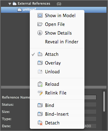
Open File Lets you open an Xref. Select the Xref from the list, and then click Open File. The Xref opens in a new drawing window.
Show Details Opens a panel at the bottom of the Reference Manager palette. It’s similar to the Properties Inspector palette in that it displays the properties of a selected external reference and also allows you to modify some of those properties. For example, the Reference Name option in the Details panel lets you give the external reference a name that is different from the Xref filename. Table 7-1 gives you a rundown of the options in the Details panel.
Table 7-1: Options in the Details panel of the Reference Manager palette
| Option | Function |
| Reference Name | Lets you give the Xref a name that is different from the Xref’s filename. This can be helpful if you want to use multiple external references of the same file. A caution will appear alerting you of the consequences of renaming the file. |
| Status | Tells you whether the Xref is loaded, unloaded, or not found. (Read-only.) |
| Size | Gives you the file size information. (Read-only.) |
| Type | Shows you which attachment method is set for the Xref. (Read-only.) |
| Date | Gives you the date and time the file was last saved. (Read-only.) |
| Saved Path | Tells you where AutoCAD expects to find the Xref file. (Read-only.) |
| Found At | Lets you select the location of the Xref file. You can click the ellipsis button to locate a lost Xref or use a different file from the original attached Xref. |
| Block Unit | Gives you the unit of the Xref block. (Read-only.) |
| Unit Factor | Displays the unit factor based on the INSUNITS system variable value of the Xref. INSUNITS is a value for scaling of blocks, images, and Xrefs. (Read-only.) |
Reveal In Finder While not an AutoCAD command, this will open the Mac OS Finder utility and show you the location of the Xref file.
Attach Toggles the attachment type to Attach if it is currently set to Overlay.
Overlay Tells AutoCAD to ignore other Xref attachments that are nested in the selected file. This avoids multiple attachments of other files and eliminates the possibility of circular references (referencing the current file into itself through another file).
Unload Removes an Xref from the current file, but maintains a link to the Xref file so that it can be quickly reattached. This has an effect similar to freezing a layer and can reduce redraw, regeneration, and file-loading times.
Reload Restores an unloaded Xref.
Relink File Opens the Select Dwg File To Relink dialog box. Works the same as the Relink File option mentioned previously.
Bind Converts an Xref into a block. This option maintains the Xref’s named elements (layers, linetypes, and text and dimension styles) by creating new layers in the current file with the Xref’s filename prefix (discussed again in Chapter 14).
Bind-Insert The Bind-Insert option is similar to the Bind option. Bind-Insert doesn’t maintain the Xref’s named elements but merges them with named elements of the same name in the current file. For example, if both the Xref and the current file have layers of the same name, the objects in the Xref are placed in the layers of the same name in the current file.
Detach Detaches an Xref from the current file. The file is then completely disassociated from the current file.
The Attach External Reference Dialog Box
The Attach External Reference dialog box, shown in Figure 7-16 earlier in this chapter, offers these options:
Browse Opens the Select Reference File dialog box to enable you to change the file you’re importing as an Xref.
Path Type Offers options for locating Xrefs. Xref files can be located anywhere on your system, including network servers. For this reason, you can easily lose links to Xrefs either by moving them or by rearranging file locations. To help you manage Xrefs, the Path Type option offers three options: Full Path, Relative Path, and No Path. Full Path retains the current full path. Relative Path maintains paths in relation to the current drawing. The current drawing must be saved before using the Relative Path option. The No Path option is for drawings in which Xrefs are located in the same folder as the current drawing or in the path specified in Support File Search Path in the Application tab of the Application Preferences dialog box. Remember, you can press F-, (comma) to open the Application Preferences dialog box.
Specify On-Screen Appears in three places. It gives you the option to enter insertion point, scale factors, and rotation angles in the dialog box or at the Command prompt, in a way similar to inserting blocks. If you clear this option for any of the corresponding parameters, the parameters change to allow input. If they’re selected, you’re prompted for those parameters after you click OK to close the dialog box. With all three Specify On-Screen check boxes cleared, the Xref is inserted in the drawing using the settings indicated in the dialog box.
Attachment Tells AutoCAD to include other Xref attachments that are nested in the selected file.
Overlay Tells AutoCAD to ignore other Xref attachments that are nested in the selected file. This avoids multiple attachments of other files and eliminates the possibility of circular references (referencing the current file into itself through another file).
Details Displays or hides the path information for the selected Xref file.
Other Xref Features Available
In addition to those mentioned, there are two other options that are used in Xref editing:
Visretain Instructs AutoCAD to remember any layer color or visibility settings of Xrefs from one editing session to the next. In the standard AutoCAD settings, this option is on by default. Visretain has two settings: 0 – Off and 1 – On.
XEdit System Variable Allows editing the drawing in place. XEdit has two settings: 0 – No and 1 – Yes.
Clipping Xref Views and Improving Performance
Xrefs are frequently used to import large drawings for reference or backgrounds. Multiple Xrefs, such as a floor plan, column grid layout, and site-plan drawing, might be combined into one file. One drawback to multiple Xrefs in earlier releases of AutoCAD was that the entire Xref was loaded into memory even if only a small portion of it was used for the final printed output. For computers with limited resources, multiple Xrefs could slow the system to a crawl.
AutoCAD offers two tools that help make display and memory use more efficient when using Xrefs: the Xclip command and the Demand Load feature.
Clipping Views with Xclip
The Xclip command lets you clip the display of an Xref or a block to any shape you want, as shown in Figure 7-18. For example, you might want to display only an L-shaped portion of a floor plan to be part of your current drawing. Xclip lets you define such a view. To access the command, type XCLIP↵.
You can clip blocks and multiple Xrefs as well. You can also specify a front and back clipping distance so that the visibility of objects in 3D space can be controlled. You can define a clip area by using polylines or spline curves, although curve-fitted polylines revert to decurved polylines. (See Chapter 17 for more on polylines and spline curves.)
Figure 7-18:The first panel shows a polyline outline of the area to be isolated with Xclip. The second panel shows how the Xref appears after Xclip is applied. The last panel shows a view of the plan with the polyline’s layer turned off.

Controlling Xref Settings via the Xloadctl System Variable
The Xloadctl system variable offers three settings: 0 – Disabled, 1 – Enabled, and 2 – Enabled With Copy. Xloadctl (also known as Demand Loading) is set to Enabled With Copy by default in the standard AutoCAD setup. In addition to reducing the amount of memory an Xref consumes, it prevents other users from editing the Xref while it’s being viewed as part of your current drawing. This helps aid drawing version control and drawing management. The Enabled With Copy option creates a copy of the source Xref file and then uses the copy, thereby enabling other AutoCAD users to edit the source Xref file.
Demand loading improves performance by loading only the parts of the referenced drawing that are needed to regenerate the current drawing. You can set the location for the Xref copy in the Application tab of the Application Preferences dialog box under Temporary External Reference File Location.
External References in the San Francisco Main Library Project
Although the exercises in this chapter demonstrate how Xrefs work, you aren’t limited to using them in the way shown here. Perhaps one of the most common ways of using Xrefs is to combine a single floor plan with different title block drawings, each with its own layer settings and title block information. In this way, single-drawing files can be reused in several drawing sheets of a final construction document set. This helps keep data consistent across drawings and reduces the number of overall drawings needed.
This is exactly how Xrefs were used in the San Francisco Main Library drawings. One floor-plan file contained most of the main information for that floor. The floor plan was then used as an Xref in another file that contained the title block as well as additional information such as furnishings or floor finish reference symbols. Layer visibility was controlled in each title block drawing so only the data related to that drawing appeared.
Multiple Xref files were also used by segregating the structural column grid layout drawings from the floor-plan files. In other cases, portions of plans from different floors were combined into the single drawing shown here by using Xrefs.

Create Unique Layer, Style, and Block Names
When you make a copy of a block from an Xref, AutoCAD needs to assign that block a name. The Create Unique Layer, Style, And Block Names option tells AutoCAD to use the original block name and append a $#$ prefix to the name (# is a numeric value starting with zero). If you were to import the Bath block, for example, it would become $0$bath in the current drawing. This ensures that the block maintains a unique name when it’s imported even if there is a block with the same name in the current drawing. If you use the BINDTYPE system variable and then type 1, the original name is maintained. If the current drawing contains a block of the same name, the imported block uses the current file’s definition of that block.
Assemble the parts. Technical drawings are often made up of repetitive parts that are drawn over and over. AutoCAD makes quick work of repetitive elements in a drawing, as shown in the first part of this chapter.
Master It What is the object used as the basic building block for the unit plan drawing in the beginning of this chapter?
Take control of the AutoCAD display. Understanding the way the AutoCAD display works can save you time, especially in a complex drawing.
Master It Name the command used to save views in AutoCAD. Describe how to recall a saved view.
Use hatch patterns in your drawings. Patterns can convey a lot of information at a glance. You can show the material of an object, or you can indicate a type of view, like a cross section, by applying hatch patterns.
Master It How do you open the Hatch And Gradient dialog box?
Understand the boundary hatch options. The boundary hatch options give you control over the way hatch patterns fill an enclosed area.
Master It Describe an island as it relates to boundary hatch patterns.
Use external references. External references are drawing files that you’ve attached to the current drawing to include as part of the drawing. Because external references aren’t part of the current file, they can be worked on at the same time as the referencing file.
Master It Describe how drawing files are attached as external references.