Common to all Enterprise Voice applications, these applications require the use of a special type of Active Directory contact object called an application contact. These application contact objects serve the purpose of providing routing information so that Office Communications Server knows how to route requests to a specific voice application. Because voice applications, similar to Enterprise Voice–enabled users, are associated with a Session Initiation Protocol (SIP) Uniform Resource Identifier (URI) and a phone number and behave as endpoints in Office Communications Server, they are routable by a phone number, as is a user. Instead of using a user object, which is an NT principal account, to represent the application, a contact object is safer because a malicious user cannot use a contact object to fraudulently log on to Active Directory. Because contact objects do not have credentials associated with them, there is no need for password management either.
Office Communications Server 2007 R2 extends the contact object with new attributes. Among these new attributes, the attribute msRTCSIP-ApplicationDestination contains the distinguished name (DN) of the Enterprise Voice application listed in the Trusted Services list in Active Directory that the contact object represents. Similar to a user being logged on to Office Communications Server from a particular client, such as Office Communicator, this DN represents the endpoint from where the Enterprise Voice application is logged on. Figure 13-4 illustrates the routing logic of an Enterprise Voice application. The user calls the application’s phone number, for example, an Auto-Attendant number. Office Communications Server, using the logic defined in Chapter 11, normalizes the number and performs a reverse number lookup (RNL) to convert the phone number into its corresponding SIP URI. Office Communications Server determines the contact object’s home server and routes the call to the appropriate server. When the request reaches the home server, it routes the call to the appropriate Enterprise Voice application. For Office Communications Server 2007 R2, Enterprise Voice applications must be running on the Standard Edition Server or Enterprise pool where the application’s contact object is homed.

While a Response Group can have agents that are homed on any pool in the enterprise, it is recommended to deploy the Response Group on the Office Communications Server pool that has the highest number of agents.
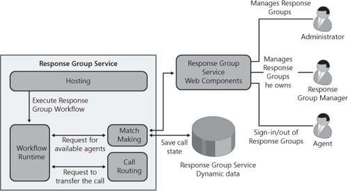
The core Response Group Service is built on top of the following components, all of which run in the main service process, ocsappserverhost. (Note that the name of the process used by the other Office Communications Server applications is the same.)
Hosting component. Responsible for accepting incoming calls
Workflow Runtime component. Responsible for running the workflow attached to each Response Group and built on the Microsoft Windows workflow foundation
Match Making component. Responsible for the following tasks:
Keeping track of agents’ presence and determining which agents are available to pick up the calls
Queuing the calls
Monitoring which agents are signed in to the system
Call Routing component. Responsible for routing the incoming call to one of the available agents
In addition to these four components, the Response Group Service has a Web Component that is used for:
Enabling the agents to sign in or sign out of the Response Groups. This functionality is implemented as a tab for the Office Communicator client and also in the Agent Communications Panel for the Dynamics CRM 4.0 client.
Offering the Response Group Deployment tool functionality and enabling administrators and Response Group managers to administer Response Groups in a Web interface.
The Response Group Service uses a database to store dynamic data used in call routing. This database, called acddyn, is installed on the SQL back-end server in the case of an Enterprise pool or on the local SQL Express in the case of a Standard Edition Server. In Enterprise Edition, this database offers high availability in case a front-end server goes down. Figure 13-5 shows the logical component architecture for the Response Group Service.
In addition, the Response Group Service is using RTCconfig as a database to store all its configuration settings. This is the same database Office Communications Server uses for its settings.
The Hosting component is an entity that handles the interaction with the Office Communications Server Hosting Service and is able to receive audio calls from a client application. There is one instance of the Hosting component for each Response Group Service. The Hosting component is implemented as a SIP application agent that is addressable by using any of the Response Group URIs.
The Hosting component is responsible for the following tasks:
Starting and initializing the Response Group Service components
Accepting incoming calls
Validating incoming calls
Instantiating the specific workflow for each Response Group
When an incoming call is received, the Hosting component validates that the incoming call is an audio-only call. After this is done, the Hosting component fetches the settings for the Response Group associated with the called phone number or SIP URI from the RTCconfig database and instantiates the workflow.
The Workflow Runtime component provides the environment under which the Response Group’s workflows are run. The Response Group Service Workflow Runtime component is built using Microsoft Workflow Runtime. The component creates a new workflow instance for each incoming call and controls its execution.
The workflow component is responsible for asking the caller questions, recording the caller’s answers, and playing music-on-hold while the Response Group Service routes the call by using the Call Routing component.
The Response Group Service offers four predefined templates that the administrator can use when configuring a new workflow. Table 13-1 summarizes the capabilities of each of these templates. Two of the Response Group templates are for hunt groups and two others are for interactive templates, such as templates that use questions and answers.
Table 13-1. Capabilities Offered in Four Supported Response Group Templates
TEMPLATE NAME | ||||
|---|---|---|---|---|
CAPABILITIES | BASIC HUNT GROUP | ENHANCED HUNT GROUP | ONE-LEVEL INTERACTIVE TEMPLATE | TWO-LEVEL INTERACTIVE TEMPLATE |
Activation of the Response Group and contact object selection | Yes | Yes | Yes | Yes |
Language selection | Yes[*] | Yes | Yes | Yes |
Welcome message | No | Yes | Yes | Yes |
Availability and holiday configuration | No | Yes | Yes | Yes |
Question and answers | No | No | Yes | Yes |
Assignment of Response Group managers | Yes | Yes | No | No |
[*] This is in the user interface (UI) for consistency reasons, but the language selection has no impact. | ||||
The Match Making component is responsible for keeping track of available agents and calls in the queue and creating a match between them. This means finding an available agent for a call in the queue and finding a call to be handled when an agent becomes available. This component tracks the availability of agents, to which groups they are assigned, and the lists of callers in the different Response Group queues. The Match Making component subscribes to agents’ presence to determine if an agent is available to answer a call. Information about calls processed by the Response Group Service—such as call ID, the serving queue, calling URI, and the workflow that should service the incoming call—is stored in the pool’s back-end database.
There is a Match Making instance on each front-end server in an Enterprise pool deployment, each of which is connected to the pool back end. In each pool, only one Match Making instance can assume the role of finding the available agents for an incoming call. This instance is called the active instance. All other Match Making instances query the active Match Making instance to get the list of available agents. Figure 13-6 shows the interaction between the active Match Making instance and nonactive Match Making instances.

If the active Match Making instance fails, this active role is assumed by one of the other Match Making instances in the pool. To determine which Match Making instance becomes the new "active" instance, the Response Group Service uses a record in its database, acddyn. Each Match Making instance tries to update that record, writing its own fully qualified domain name (FQDN) and updating a timestamp. The instances first check the timestamp of the record. If the timestamp is not older than 10 seconds, the record specifies the FQDN of the active Match Making instance. If the record is expired, the other instances attempt to update the record with their own FQDN and update the timestamp of the record. The record is considered expired if the timestamp is older than 10 seconds. After an instance becomes active and has successfully published its own FQDN, it must periodically update the record to keep its role as an active instance. As it is being carried out, the workflow issues a request to the Match Making service that returns, based on the Response Group configuration and current user availability, one or more agents to whom the call can be routed.
The main role of the Match Making instance is to service requests coming from the workflow components on the different front ends in a pool. The Workflow component expects Match Making to return a set of one or more agents that are available to answer the incoming call. To build this result set, Match Making fetches first the queue settings from the RTCconfig database, such as:
The list of groups of agents that serve the given queue
The list of agents and their presence status
Based on this information, Match Making determines which agents are available to answer the incoming call. This list of available agents is returned to the Workflow component.
The Call Routing component is the entity that actually performs the routing of calls from the Response Group to one or more agents. This component performs different types of routing, as explained in Table 13-2.
Table 13-2. Summary of Response Group Service Routing Methods
ROUTING METHOD | DEFINITION | WHEN TO USE IT |
|---|---|---|
Serial routing | Agents in the group are called one after another in a predefined order determined by the administrator. Each call attempts to ring the first agent in the list if he is available, then the second in the list, and so on. Note that this routing method makes sense only when an administrator-created group used as the admin can define the ordered list. If a distribution list is used, the list is randomly ordered by the system. | When there is a clear list of people who should be receiving a call, starting first with the ideal, next with the second-best choice, and so on. |
Parallel routing | All available agents are called at the same time for every incoming call. The first agent who accepts the call from the Response Group Service gets the call routed to her. All other agents get a notification telling them that the call has been accepted by another agent. | When all agents are equally qualified to respond:
|
Longest Idle | The agent who has been idle for the longest time receives the call in this configuration. | When calls should be equally distributed amongst all agents so that all agents receive approximately the same call volume. This method works well in higher-call-volume scenarios. |
Round Robin | Calls are routed to all available agents in a round-robin manner. | When calls should be equally distributed amongst all agents such that all agents receive approximately the same call volume. The calls are distributed to the agents in a round-robin manner in the order the administrator defines. |
This section details a sample call flow in a serial routing example in which the Response Group is configured for serial routing to agent 1 and then agent 2. The following text describes the main steps in the scenario.
Step 1: Call to the Response Group To use the Response Group Service routing features, the caller must establish an audio session with a Response Group. This is done by placing an audio call from a client application to the Response Group SIP URI.
Step 2: Interactive Voice Response portion After the audio call is established between the caller and the Response Group Service, the caller goes through the IVR portion (note that this is only the case if it is not a hunt group; in a hunt group scenario, the logic proceeds directly with the next step).
Step 3: Request match After the caller has finished going through the IVR, the call is placed in a queue and the Workflow Runtime component requests the Match Making component for a target agent—or a set of target agents in a parallel routing scenario—it should route the call to. Note that if no agent is available, the call is placed on music-on-hold until an agent becomes available or until the queue timeout is reached.
Step 4: Alert agent After the Match Making component has returned the agent or set of agents, the Call Routing component calls that agent(s). This is a consultative call. The consultative call results in a system alert being displayed to the agent showing which Response Group Service the call is coming from and who the caller is. At that point, the agent has the choice to accept or not accept the consultative call. If the agent declines the consultative call, a new target agent is requested and the Call Routing component will make a new consultative call to that agent. After an agent accepts the consultative call, the Call Routing component attempts to transfer the call to the agent, as described in the next step.
Step 5: Transfer call from the caller to the agent After an agent accepts the consultative call from call routing, the agent is transferred to the caller. Upon completion of the transfer, the caller drops the connection with the Response Group Service, and the service disconnects the consultative call with the agent. If call routing had consulted several agents in parallel, the remaining consultative calls would be cancelled, and the agents would get information about who accepted the call.
Figure 13-7 shows the call flow for a declined routing attempt to an agent, followed by a successful transfer to another agent.

The Conferencing Attendant provides a simple service. It enables users dialing from the PSTN to join the audio portion of a conference. Consequently, this service is much simpler than the Response Group Service. The Conferencing Attendant distinguishes between two types of callers dialing in. One type of caller is an external user. The second type of caller is an internal user that is authenticated by Conferencing Attendant.
When calling the PSTN dial-in number of a conference, the call from the PSTN user is forwarded by the Mediation Server to the enterprise pool on which the Conferencing Attendant is homed. The enterprise pool then routes the call to the Conferencing Attendant that is associated with the phone number dialed. The Conferencing Attendant prompts the user to enter the conference ID provided in the meeting invite. It then sends the conference ID to the front-end server to resolve into the corresponding conference URI. This conference URI is the same URI as used by an Office Communicator user to join the conference by clicking the link in the meeting invite. The Conferencing Attendant joins the conference and monitors the roster for the arrival of other participants and leaders into the conference on behalf of the PSTN user. This call flow is illustrated in Figure 13-8.
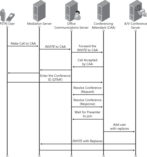
The Conferencing Attendant does not allow PSTN participants to join the conference until the leader enters the conference. The leader may use any modality and is not required to use the audio modality. PSTN participants are played music while on hold until the leader enters the meeting. If the leader does not join the meeting within 15 minutes, of this PSTN user being on music-on-hold, the PSTN participant is disconnected from the call by the Conferencing Attendant.
When an internal participant joins a conference using the PSTN dial-in number, the Conferencing Attendant can authenticate the user before joining them to the conference. After entering the DTMF tones for the conference ID, the user has the option to be authenticated by entering their work phone number (or extension) and personal identification number (PIN). The Conferencing Attendant verifies the user information and then transfers the user to the conference using their SIP URI identity. This call flow is shown in Figure 13-9.
