This section of the chapter provides a technical overview of Office Communications Server 2007 R2 and its new features, which include:
Reference topology
Group Chat architecture
Desktop sharing framework
Server Application framework
SIP trunking topology
Media enhancements
Figure 2-1 shows the Office Communications Server 2007 R2 consolidated topology.
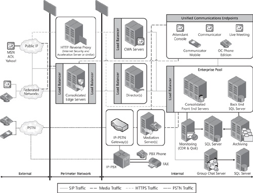
In the Office Communications Server 2007 R2 consolidated pool topology, the following server roles and services are collocated on the same computer as the front-end server:
Address Book Service
Application Server
Application Sharing Conferencing Server
A/V Conferencing Server
Conference Announcement Service (optional)
Conference Attendant (optional)
Group Expansion Service
IM Conferencing Server
Outside Voice Control (optional)
Response Group Service (optional)
Telephony Conferencing Server
Update Server
Web Conferencing Server
In the Office Communications Server 2007 R2 consolidated Edge topology, the following server roles and services are collocated on the same computer as the Office Communications Server 2007 R2 Edge Server:
Access Edge Server
A/V Edge Server
Web Conferencing Edge Server
For additional information on server roles, see Chapter 3.
Office Communications Server 2007 R2 Group Chat enables users to engage in persistent IM conversations. For details about Group Chat features, see Group Chat Feature.
The minimum configuration and simplest deployment for Group Chat is a single-server topology, which includes the following computers:
A single Group Chat Server running the following three server roles:
Lookup Server The Lookup Server provides the chat room address, distributes sessions to Channel Servers, and in multiple-server topologies manages load balancing.
Channel Server The Channel Server provides core functionality for chat rooms except for file posting, which is managed through the Web Service.
Web Service The Web Service is used to post files to group channels. Internet Information Services (IIS) version 6.0 hosts the Web Service.
The Group Chat Server, like other Office Communications Server 2007 R2 servers, requires a 64-bit computer. This computer hosts the Microsoft SQL Server database for storing ongoing and archival chat data, as well as information about categories and channels that are created, user provisioning information from the Group Chat Administration Tool and initial sign-in, and basic configuration information about the Group Chat Servers.
Group Chat client computers. These computers are not required to be 64 bit.
If compliance is required, the single-server topology must also include the following:
Compliance Server. If configured, the Group Chat compliance feature archives a comprehensive record of both logged and unlogged group chat activity. IM content is not archived unless archiving is configured in Office Communications Server. In this case, IM content is archived on the Archiving Server.
SQL Server Database. This database can be either the Group Chat database or a separate database on the Compliance Server.
Figure 2-2 shows all of the components of a topology with a single Group Chat Server and optional Compliance Server with a separate compliance database.

Figure 2-3 shows a multiple-server Group Chat topology.

Administration of Group Chat from a separate computer (such as an administrative console) requires installation of the following on the computer:
Group Chat Administration Tool
All of these computers must be deployed in the following ways:
In an Active Directory domain, with at least one global catalog server in the forest root
Outside the Office Communications Server 2007 R2 pool
Office Communications Server 2007 R2 supports desktop sharing in both peer-to-peer and conference scenarios. For details about supported functionality, see the section titled "Desktop Sharing" earlier in this chapter. The framework for sharing desktops includes the following principal components:
Communicator Web Access client. The 2007 R2 version of the Communicator Web Access client contains the hosting and viewing components for desktop sharing. The hosting component drives the desktop sharing session. This component sends graphical data to the Application Sharing Server or another client, such as Office Communicator 2007 R2, which is capable of understanding Remote Desktop Protocol (RDP). The viewing component displays the graphical data from the desktop sharing session to the user. Graphical data is obtained from the Communicator Web Access server. The viewer can also send keyboard and mouse data to the host by way of the Communicator Web Access server and the Application Sharing Conferencing Server.
Desktop-sharing client. The desktop sharing client is a Web-based viewer that is hosted on the Communicator Web Access client. When sharing is initiated, meeting participants are invited to view the sharer’s desktop. If they accept, the desktop sharing client launches in a new viewing pane integrated with the Communicator Web Access client. Participants using Office Communicator 2007 R2 can launch the desktop sharing client directly from Communicator. Each participant’s desktop sharing client receives graphical data from the Communicator Web Access server, which in turn receives it from the Application Sharing Conferencing Server.
Microsoft Office Communicator Web Access plug-in. Because the desktop sharing client is browser based, interaction with the underlying operating system has to be implemented through a native plug-in. The Microsoft Office Communicator Web Access plug-in is available as an option during installation of the Communicator Web Access client.
Communicator Web Access Server. The Communicator Web Access server is responsible for setting up, tearing down, and controlling the desktop sharing session for the Communicator Web Access client. The Communicator Web Access server also sends and receives sharing data both to and from the client. The Communicator Web Access server handles media only for Communicator Web Access viewers.
Application Sharing Conferencing Server. The Application Sharing Server is responsible for managing and streaming data for conferences that require desktop sharing. In multiparty conferences, the Communicator Web Access client, in the role of desktop sharing host, dials the conferencing server directly (or, in the case of external users, by way of an A/V Edge Server). The Communicator Web Access server connects to the conferencing server to receive desktop sharing data on behalf of the Web clients hosted on the Communicator Web Access server.
In Office Communications Server 2007 R2, desktop sharing components use RDP, which is also used by Terminal Services functionality in Microsoft Server 2003. Desktop sharing sessions that use RDP cannot support participants who are running earlier versions of Office Communications Server clients, nor can they include users of the office Live Meeting service. However, participants who are not running any Office Communications Server clients and do not have an Office Communications Server account can be invited to a desktop sharing session and join that session by navigating to a meeting URL hosted on the Communicator Web Access server, using a supported Internet browser.
In peer-to-peer scenarios, if either participant is running the Communicator Web Access client, starting a desktop sharing session escalates the conversation to a two-party conference involving the Application Sharing Conferencing Server. This escalation is necessary because the Communicator Web Access client relies on an RDP connection with the Application Sharing Conferencing Server. After a session escalates to a conference, it cannot revert to a peer-to-peer conversation.
If the conference organizer initiates the conference with desktop sharing as the initial mode, the organizer’s client first joins the Focus, and then it joins the Application Sharing Conferencing Server as a "sharer." Then, the organizer’s client invites other parties to join the conference. They, in turn, join the Focus, and then they join the Application Sharing Conferencing Server.
If application sharing is introduced in an ongoing conference that began in a different mode, the sharer joins the Application Sharing Conferencing Server, which causes the Focus to send a roster update to other participants. This roster update includes an invitation to view the sharer’s desktop.
This topic provides an overview of the new application infrastructure introduced with Office Communications Server 2007 R2.
The Office Communications Server 2007 R2 infrastructure includes the following components.
The Application Server is a new component on the Office Communications Server 2007 R2 front-end server. The Application Server provides a platform to deploy, host, and manage UC applications. By providing applications with essential services and a consistent model for installation, activation, provisioning, and upgrading, the Application Server simplifies application development, deployment, and administration.
In this discussion, an application refers to a UC application that is hosted on the Application Server. Each Application Server in a pool hosts a separate instance of a given application. Each application instance is defined by a specific fully qualified domain name (FQDN).
The Office Communications Server 2007 R2 Deployment Wizard installs the Application Server automatically as a separate process on the same computer as the front-end server. No administrator input is required. In addition, no settings are required to configure the Application Server, although the same pool name and pool certificate are used by all Application Server computers in a pool. The Application Server always runs as a separate process on the front-end server and cannot be deployed on a separate computer in the pool.
Once the Application Server is installed, the Deployment Wizard offers to activate four applications:
Conferencing Attendant
Conferencing Announcement Service
Response Group Service
Outside Voice Control
The administrator can choose to activate one or more of the applications or none at all.
Application deployment must be identical on all Application Servers in a pool. That is, if Conferencing Attendant, for example, is deployed on one Application Server, it must be deployed on all Application Servers in the pool.
The administrator can manage application-specific settings for all applications, except Response Group Service, using the Office Communications Server 2007 R2 Administrative snap-in. You can administer Response Group Service by using its separate Administrative snap-in.
For details about these applications, see the section titled "Server Applications" earlier in this chapter.
The Application Server does not start or stop independently from the applications it hosts. As each application instance is activated, it is added to the list of applications on the computer.
When an application is activated, the application is provisioned with contact objects and trusted service entries such that calls can be routed to it. This provisioning information includes the phone number or SIP URI associated with the application and the SIP port, as well as the FQDNs of the multiple instances of the application.
For purposes of call routing, each application is represented in the Office Communications Server 2007 R2 consolidated configuration by a contact object, which lists the Virtual IP (VIP) address and port of a hardware load balancer that has been configured with the IP addresses of all corresponding instances of the Application Server. The Application Server does not provide a single SIP listening port on behalf of all hosted applications. Instead, each application listens separately, using its own port. The hardware load balancer directs calls to different application instances according to its own proprietary algorithms.
Contact objects are required to enable applications to function as SIP endpoints, which can be provisioned with SIP URIs and can receive and send calls as if they were end users. Contact objects required for an application’s internal use are created during activation if the required information is provided in the application manifest file.
Contact objects that function as SIP endpoints to make an application available to external users are created after deployment and activation by using the Office Communications Server 2007 R2 Administrative snap-in.
The Response Group Service enables users to create response groups that automatically distribute incoming calls to groups of agents. It also enables users to configure other settings, such as a welcome message, Interactive Voice Response, and music-on-hold.
The Response Group Service can be installed:
On Office Communications Server 2007 R2 Standard Edition or Enterprise Edition.
In a consolidated configuration or in an expanded configuration.
Response Group Service must be installed and identically configured on all front-end servers in a pool.
For best performance, it is recommended that you install the Response Group Service on Office Communications Server 2007 R2 servers at every location where response groups are required and an IP-PSTN gateway is deployed.
Figure 2-4 shows the Response Group Service deployed on Office Communications Server 2007 R2 Enterprise Edition servers in a consolidated configuration. In this example, calls from on-site and remote callers can be distributed to on-site and remote callees.

Dial-in conferencing enables anonymous users and enterprise users who want or need to use a PSTN phone to join the audio portion of an on-premises conference. Each conference that is enabled for PSTN dial-in includes the following information in the conference invitation:
A numeric-only PSTN conference ID. The ID uniquely identifies the conference.
One or more PSTN access numbers with associated language support.
A link to an Office Communicator Web Access page containing a list of all other access numbers and instructions for how to set the user’s PIN.
In addition, the conference invitation might include a numeric-only pass code for the conference that can be used by anonymous users.
Dial-in support is available to both enterprise and anonymous users. An enterprise user is one with Active Directory Domain Services credentials. An anonymous user does not have enterprise credentials but has been invited to the conference. A federated user who uses the PSTN to connect to a conference is considered to be an anonymous user in this context.
Enterprise users or conference leaders who join a PSTN conference dial one of the conference access numbers. Then, they enter their PSTN conference ID, followed by their UC extensions and PINs. The combination of extension and PIN enables the Conferencing Attendant to map enterprise users to their Active Directory credentials. As a result, enterprise users can be authenticated and identified by name in the conference. They can also assume a conference role predefined by the organizer.
Anonymous users who join a PSTN conference dial one of the conference access numbers, and then they enter a PSTN conference ID and a pass code for the conference if there is one. Anonymous users are not identified by name and cannot be assigned a predefined role.
A conference access number maps to the SIP URI of the Conferencing Attendant. When a PSTN user calls a conference access number, the meeting Focus initiates phone number lookup to obtain the SIP URI of the allocated Conferencing Attendant. The Mediation Server directs the call to the allocated Conferencing Attendant, which accepts the conference ID and passes it (in encrypted form) in a SIP SERVICE request to the front-end server.
The front-end server looks up the conference on the organizer’s home server and returns the conference URL to the Conferencing Attendant in the response to the SERVICE request. The Conferencing Attendant uses the conference URL to join the Focus and send a dial-out command to the A/V Conferencing Server. The A/V Conferencing Server adds the caller to the conference, at which point the initial connection between the Mediation Server and the Conferencing Attendant is dropped.
Conferencing Announcement Service plays entry and exit tones to the PSTN participants in an audio conference. When a PSTN user calls into the conference, the A/V Conferencing Server adds an instance of Conferencing Announcement Service to the conference for the purpose of announcing the caller.
When a PSTN user dials in to a conference, the A/V Conferencing Server determines that the connection is from the PSTN and whether a Conferencing Announcement Service is already active for the conference. If not, the A/V Conferencing Server requests a new instance of Conferencing Announcement Service and invites it to join the conference. Conferencing Announcement Service plays the entry and exit tone for each PSTN participant. Conferencing Announcement Service also announces to PSTN callers whether they have been muted or unmuted.
Outside Voice Control acts as an intermediary to connect mobile devices and UC endpoints. The mobile devices must be running 2007 R2 version of Microsoft Office Communicator Mobile for Windows Mobile.
Users with mobile devices running this client can send and receive voice calls as if their phones were part of the enterprise network instead of the cellular carrier network.
When a user makes a call from a supported mobile client to an enterprise peer, Outside Voice Control sets up the call as summarized in the following steps.
The mobile client uses a data-signaling channel to inform Outside Voice Control of the outbound call.
Outside Voice Control initiates a request to the Mediation Server and PSTN gateway to establish a call to the mobile client by using the mobile client’s cellular network.
A cellular call is established with the mobile client. This is the first call leg.
Outside Voice Control establishes a second call leg with the home pool of the enterprise peer that is the recipient of the call.
A front-end Server in the recipient’s home pool looks up the recipient’s registered endpoints and then forks the call to all the recipient’s endpoints, including mobile devices.
The second call leg is established with the endpoint that answers the call.
Outside Voice Control provides call management to bridge the two call legs between the mobile client and the enterprise peer. Media flows between the mobile client and the enterprise peer through the Mediation Server.
When an enterprise user or a phone user makes a call to a supported mobile client by using one-number calling, Outside Voice Control sets up the call as summarized in the following steps.
If the call originates from an enterprise peer, the call will connect directly to Office Communications Server. If the call originates from the PSTN, the call will connect to the Mediation Server.
A front-end server in the recipient’s home pool looks up the recipient’s registered endpoints and then forks the call to all the recipient’s endpoints, including the user’s cell phone that is running a supported mobile client.
When the request to establish a signaling channel reaches the supported mobile client, the mobile client is able to determine that the incoming session is an audio call.
The mobile client uses a data-signaling channel to inform Outside Voice Control of the incoming call.
The mobile client signals Office Communications Server to reroute the original signaling request to Outside Voice Control. Outside Voice Control initiates a request to a Mediation Server and PSTN gateway to establish a call to the mobile client’s cellular network.
When the user answers the call on the mobile client device, Outside Voice Control and Office Communications Server connect the Mediation Server call leg with the originating call leg. Media flows directly between the Mediation Server and the caller.
Outside Voice Control remains in the signaling path to provide call management until the call is terminated.
The term SIP trunking has various meanings within the telecommunications industry, including:
A generic means to connect one vendor’s IP Private Branch eXchange (PBX) with another vendor’s equipment
A generic means to connect multiple IP PBXs across a wide area network (WAN) within the same enterprise
A generic means for an IP PBX to connect to a remote hosted service for the purpose of originating and terminating calls to the PSTN network
This final meaning is the sense in which the term SIP trunking is used in Office Communications Server 2007 R2.
The purpose of a SIP trunk in an Office Communications Server topology is to enable an enterprise to connect its on-premises voice network to a service provider offering PSTN origination and termination. Relying on an independent server provider for PSTN connectivity eliminates the need to deploy and maintain IP-PSTN gateways.
Figure 2-5 depicts the SIP trunking topology in Office Communications Server 2007 R2.

As shown in the diagram, an IP virtual private network (VPN) is used for connectivity between the enterprise network and the PSTN service provider. The purpose of this private network is to provide IP connectivity, security, and (optionally) Quality of Service (QoS) guarantees. In such an environment, it is not required to additionally secure the SIP signaling traffic (with Transport Layer Security, or TLS) or the media traffic (with Secure Real-Time Protocol, or SRTP). Connections between the enterprise and the service provider therefore consist of plain TCP connections for SIP and plain RTP (over UDP) for media potentially tunneled through an IP VPN.
It is expected that the demarcation point in most service providers’ networks will be a session border controller, although this is not required. Likewise, whether to use an IP-PSTN gateway or softswitch in the service provider network is up to the service provider.
In this SIP trunking topology, the Mediation Server performs media and signaling translation, just as it does when connected to an enterprise IP-PSTN gateway. All SIP traffic and media traffic between the enterprise network and the service provider network flows through the VPN and the Mediation Server.
The Mediation Server can discover the service provider proxy (the Session Border Controller in Figure 2-5) either through:
Static provisioning, in which the Mediation Server is provisioned manually with a list of one or more FQDNs or IP addresses that represent the set of service provider proxies through which a connection should be tried.
A Domain Name System (DNS) query against an FQDN published by the PSTN service provider.
The PSTN service provider can use either of these methods for discovering the list of enterprise proxies (Mediation Servers) to which it can connect.
Media enhancements for Office Communications Server 2007 R2 support new collaboration scenarios and improve the overall quality of experience in all A/V scenarios.
This section provides a technical overview of the following media enhancements:
Early media support
ICE protocol upgrade
Video negotiation
Early media refers to audio and video that is exchanged before the recipient accepts a call. Early media generated by the caller include voice commands or DTMF tones to activate Interactive Voice Response (IVR) systems. Early media generated by the call recipient include ringback tones, announcements, and requests for input.
Enhanced early media support in Office Communications Server 2007 R2 enables a caller to hear a ringback tone generated by the call recipient’s mobile phone. This is also the case in team call scenarios, in which a call is routed to two team members, one of whom has configured simultaneous ringing for her mobile phone. Enhanced early media support also enables call connectivity checks while a call is ringing rather than only after it is connected, as is the case in Office Communications Server 2007.
The Interactive Connectivity Establishment (ICE) implementation for Office Communications Server 2007 R2 complies with the latest ICE draft. This enhancement makes it possible for Office Communications Server 2007 R2 users to call users on Office Communications Server 2007 or on Voice over Internet Protocol (VoIP) UC phones supporting the latest ICE draft without requiring a PSTN gateway to connect the endpoints. Figure 2-6 illustrates the main scenarios.

Video negotiation is a process whereby an endpoint proposing to send video can determine the video capabilities of the receiving endpoint prior to sending the video stream. The purpose of video negotiation is to make sure that the sending endpoint can produce and send a given resolution and that the receiving endpoint can receive and render that same resolution. The negotiation follows an offer/answer model until common agreement is found. The highest-quality video capability held in common is used in peer-to-peer calls unless the user at the receiving end prefers a lower resolution or frame rate.
An endpoint’s video capability is based on several qualities, including central processing unit (CPU), available memory, attached devices, and network resources. For example, a user may have a camera that can send VGA video at 15 frames per second (fps) or Common Intermediate Format (CIF) video at 30 fps, but that cannot handle high-definition (HD) video. Video negotiation always resolves to CIF at 15 fps for multiparty video conferencing.
The video preference of the user at the receiving endpoint also helps to determine the final negotiated format. For example, a user may want to select a smaller video window even though the negotiated video settings enable a higher resolution. In such cases, the receiver instructs the sender to adopt a lower video format. The ability to specify video preferences in this way prevents inefficient use of bandwidth. Office Communicator offers three window sizes and therefore three preference settings: small, large, and full screen.