The 3D panel is one of the most versatile and comprehensive panels in Photoshop. Almost everything you can do with a 3D scene can be done from this one panel, and you can do lots of things with 3D scenes.
The panel is so versatile because it is actually four different panels, one each for meshes, materials, and lights, each with unique settings that allow you to make changes to each one of these areas of a 3D scene. The default panel, the 3D {Scene} panel, allows you to access all these settings by selecting different layers that represent different aspects of the scene.
Feeling overwhelmed yet? Well, you don't need to be; it's all very organized. This chapter breaks it down for you.
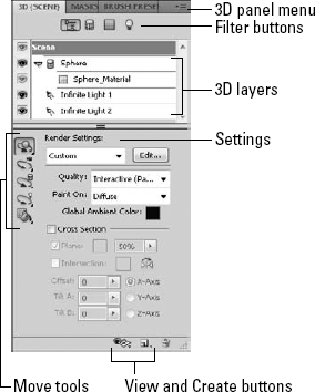
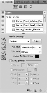
Figure 23.1 shows the 3D panel as it appears when a 3D layer is selected. You can see that it has multiple options. Individual options are covered in detail throughout this chapter, but these are the main areas:
Panel menu: Just like any panel, the 3D panel has a menu that allows you to change your settings and select preferences.
Filter buttons: The filter buttons allow you to toggle through the different objects available in a 3D scene and make changes to them. The 3D scene button shows the meshes, materials, and lights and allows you to make changes to them by selecting their layer. The other three buttons show you meshes, materials, or lights, respectively.
3D layers: Just like a miniature version of the Layers panel, these layers display the individual editable items in a 3D scene, respective to the filter that is used to display them. You can select these layers and edit their contents individually.
Manipulation tools: The manipulation tools are a new addition to the 3D panel in CS5. Available no matter which filter is selected, these tools activate the options bar and not only allow you to move the 3D object or camera but also the 3D mesh and any lights that are placed in the scene. A Materials drop button allows you to quickly add or change materials over the entire selected 3D object.
Settings: The settings area of the 3D panel changes dramatically based on which layer is selected. If you select a 3D mesh layer, the settings specify shadow settings, for instance.
View and Create buttons: At the bottom of the 3D panel are buttons that allow you to toggle the view of several aspects of your 3D scene and create new lights. A delete button gives you the option to delete any of the layers contained in your 3D scene.
When you click the Whole Scene filter at the top of the 3D panel, you display every option available in your scene. You see the meshes, the materials applied to those meshes, and the lights placed in the scene. If you have a very basic 3D object selected, as shown in Figure 23.1, these layers are manageable and easy to see. The more complicated your object is, the more likely you are to have multiple layers that make it difficult to see and work with individual aspects of your scene, as shown in Figure 23.2. As your object becomes more complicated, it is to your advantage to use the other filters to make working with the different aspects of your object easier.
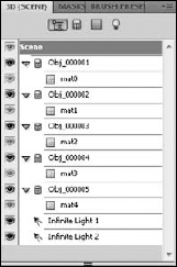
Figure 23.2. A complicated 3D object has so many layers in the scene that it is much easier to use the filters to reduce the number of layers displayed.
Using the Whole Scene filter, you can change the render settings of your scene. Before you do that, however, you want to be aware of the 3D preferences that are available.
The 3D preferences are accessed by choosing Edit

Change these options in the Preferences dialog box:
GPU Memory (VRAM): This sets the amount of video memory that Photoshop is allowed to use. 3D files are memory-intensive enough that as you work with them, you may feel like you've gone back a decade in the speed and ease of use in Photoshop. If you can afford the memory, give Photoshop the maximum amount.
Interactive Rendering: Two settings are available here: OpenGL, which renders your object relatively quickly and fairly accurately, and Ray Tracer, which is the highest quality rendering you can do. If you want to render shadows, reflections, and refractions, you must use the Ray Tracer setting. It also adds depth to your texture and gives a more realistic look than OpenGL. The Ray Tracer setting is incredibly memory-intensive, and even simple movements take time. Your best option is to leave your preferences set to OpenGL until you need to have the Ray Tracer settings on—at the end of a composite creation, for example. Figure 23.4 shows the difference between the OpenGL render and the Ray Tracer.
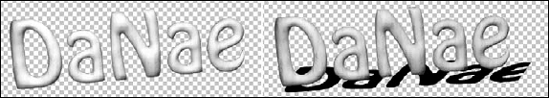
Figure 23.4. The first image is rendered using OpenGL. Although it is accurately depicted, it lacks the depth and shadow of the second image, which is rendered using the Ray Tracer setting.
Note
In order to use the OpenGL render setting, you need to have a video card that supports it. If your video card does not support it, your options default to the Ray Tracer setting. If this is the case, you can change your render settings in the 3D panel so you are not working with a fully rendered object at all times.
3D Overlays: These options simply allow you to set the colors in which your 3D objects and meshes appear.
Ground Plane: This option allows you to set the size and color of your ground plane. The ground plane in your scene simulates the ground in your view, setting perspective and catching shadows. The ground plane is discussed in greater detail later in this chapter.
Ray Tracer: If you've chosen to render your objects using the Ray Tracer setting, you can set the quality of the rendering here. The merits are obvious; you can render more quickly with a lower quality, but it doesn't look as good. If you can't use OpenGL, setting this quality to 1 or 2 until you are ready to print or collapse your file is a good option for speeding up your work.
3D File Loading: These options allow you to set initial limits on the lights and textures that are allowed to be active on an object that you are opening. Photoshop doesn't remove extra lights and textures; they simply are turned off. They can be activated again using the 3D panel.
When you have the Whole Scene filter selected, the layers in the 3D panel are headed by a layer labeled Scene. With this layer selected, the render settings are active in the settings area of the 3D panel, as shown in Figure 23.5. These settings can be adjusted so you can view your 3D scene at varying qualities and speed up your processing time. As with all the best options in Photoshop, a preset menu contains several options as well as the ability to customize the settings just the way you want them.
Whenever you bring or even create a new 3D object from the Photoshop presets, the render settings are already custom settings based on the settings that were specified previously for that object. Most of the time, these settings are higher quality settings, giving you the best preview of the object but using a high amount of computer resources. While you are positioning objects and creating scenes, you may not want the wait time that previewing the finished object can generate. Choosing a less-complicated render saves you time.
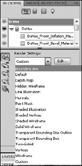
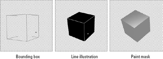
I wish I could tell you that the render presets were in order from the least complicated to the most, but the list is in alphabetical order, as you can see in Figure 23.6. Most of the render settings are somewhat self-explanatory, and clicking each gives you a preview. The simplest setting, Bounding Box, creates a bounding box around the area of your 3D object and turns off the visibility of the object itself. This is the fastest and easiest render, giving you maximum capability when it comes to movement. Other settings fall in the middle, rendering your object as a wireframe or shaded object. Figure 23.7 shows an example of three render settings.
Click the Edit button to the right of the drop-down list of render presets, and the 3D Render Settings dialog box opens, as you can see in Figure 23.8. These options allow you to customize how your 3D objects are rendered so you can create the perfect balance between processing speed and best view.
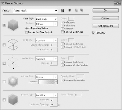
Most of these options can be selected in conjunction with one another, depending on the settings you choose. For instance, you can create a paint mask and check the edges option to show the wireframe to create a shaded wireframe rendering. These are the main options available in the 3D Render Settings dialog box:
Face options: These settings determine how the surfaces on your 3D model appear. You can choose from several face styles that include everything from the texture that has been placed on the model to a simple paint mask. If you choose unlit texture, you can use the texture option to change the way the texture looks. Other options are available with other face styles as well as if you are rendering ray traced objects.
Edge options: These allow you to adjust the look of the edges of your object. You can make them bolder or add more edges by increasing the crease threshold. A basic wireframe is one of the best options for viewing your object efficiently while manipulating it.
Vertex options: Vertices are the points made by the junctions of the polygons that make up the frame of the 3D model. The Vertex options allow you to view and make changes to the way these points appear on your object.
Volume options: If your 3D object is a volume created from DICOM images, this option allows you to make changes in the way it can be viewed.
Stereo options: If you want to render your 3D object so it can be viewed with 3D glasses, choose this option to set the stereo options.
Again you are given the opportunity to improve the quality of your rendering by sacrificing processing time. This option is set by default to render your 3D object in Interactive (painting) mode so that as you manipulate and edit your objects, you are working with them in real time rather than waiting after each move for your object to be re-rendered. When you are finished creating, manipulating, and adding texture to your object, you want the final draft to be rendered in the highest quality possible. At this point, choose Ray Traced Final Draft from the Quality drop-down menu. This process takes several minutes at best, so be sure you are ready to complete the final rendering.
The Paint On option allows you to choose a texture to use to paint on using the 3D paint mode. If you choose a texture that has not been created for your object, Photoshop creates it for you. Painting on these textures doesn't actually leave painted pixels behind; it just makes changes to the texture. When you paint on a glossy texture, for instance, you make changes to the glossiness of your 3D object.
Creating a cross section is another very versatile option found in the scene settings within the 3D panel. A cross section is created by cutting into a 3D object and looking into it. Cross sections have several varied uses.
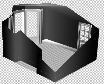
Cross sections are great for use with architectural renderings. A cross section allows you to see inside the models of 3D buildings. You can see in Figure 23.9 that I cut the roof off this simple room to show you the inside of it. You can see that this could be a very valuable application for looking at or editing more complex buildings or furnished rooms.
You also can use cross sections to cut down any 3D model for use in a composite. You can intersect a cross-sectioned object with another object or image, or you can just use the cut down version of an object. By using two instances of the same 3D model, you can open a previously solid object, such as a box, by creating matching cross sections.
Select the Cross Section box in the Render Settings area of the 3D panel to get started. Your 3D object is cut exactly in half along the X axis, as shown in Figure 23.10. Using the settings, you can create a cross section on any plane, position it anywhere on your object, and tilt it from side to side or back to front.

When you create a cross section, you can set the following options:
Plane: When this box is selected, a plane is created that is a visual aid showing you exactly how the cross section is cutting your object in two. You probably want to keep the plane on while you are adjusting the settings for your cross section in order to give yourself a guide to what you are doing. You can change the color or opacity of the plane.
Intersection: Click this box to outline the areas of the object that have been affected by the cross section. You can change the color of the outline by clicking the color box and making the change.
Flip: Check this box to determine which half of the object to show. If I had checked this option when I created the cross section for Figure 23.9, I would have seen the roof of the house, instead of the floor.
Offset: When you enable a cross section, your 3D object is cut exactly in half. By changing the offset, you can move that dividing line to cut off more or less of your object.
Tilt: The tilt settings change the angle of the cross section. By default, the angle of the cut is parallel with the base of your object. Tilt A changes the angle of the cross section front to back, and Tilt B changes the angle side to side.
Axis: You can click any of the axis indicators to change the cross section to the indicated axis. The room in Figure 23.9 is cut along the Z-axis, while the balloon in Figure 23.10 is cut along the X-axis.
You can change the view of your 3D scene using the Toggle the 3D Extras icon at the bottom of the 3D panel, as seen in Figure 23.11. You can use the drop-down menu that appears when you click the icon to change the visibility of these features in your 3D workspace:

3D Axis: This option toggles the visibility of the 3D Axis Widget. The widget has its own menu bar with the option to close the widget. After you've closed it, however, the easiest way to bring it back up is to select this option.
3D Ground Plane: In order to catch shadows and help to set perspective, a ground plane has been placed in the 3D workspace in Photoshop. You can see what it looks like when you turn it on in Figure 23.12. You can't edit or adjust this ground plane as you would be able to do in a 3D modeling program, but you can move your 3D objects in relation to it. For instance, you can lift your objects up off of the ground plane, and the shadows falling from them reflect the idea that your object is floating.
3D Light: Normally, you wouldn't want to see the lights in your scene, but as you are placing and adjusting them, they are so much easier to work with if you toggle their visibility on.
3D Selection: This option allows you to toggle the visibility of the bounding box around your 3D object.

When you want to concentrate on making changes to the 3D object itself, select the Meshes filter icon from the 3D panel. This shows the 3D {Mesh} panel, as shown in Figure 23.13. The 3D mesh is the object itself—no textures, no lights, just the edges and vertices that make up the shape and form of the object. Some objects have more than one mesh. By selecting an individual mesh, you can manipulate it and edit its properties.
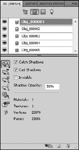
The sword shown in Figure 23.14 contains the five meshes shown in Figure 23.13. These meshes include the blade, the grip, the guard, the pommel, and the tiny button on top of the pommel. You can select any one of these meshes from the 3D layers and change these settings:
Catch Shadows: Selecting this setting allows your object to catch shadows that are cast by other objects in your scene.
Cast Shadows: This allows your object to cast shadows. In order for your object to catch or cast shadows, at least one light must be placed in your scene.
Invisible: This option turns off the visibility of the selected mesh, but leaves the shadows cast on the surface of the mesh behind.
Shadow Opacity: This setting allows you to set the shadow opacity higher or lower to cast harder or softer shadows.

Note
You can rename a mesh, or any other 3D layer, by double-clicking its name.
Under the options in the settings area of the 3D panel, you see information displayed about the mesh you have selected. You see the number of materials and textures applied to your mesh, as well as the number of vertices and faces that make up your mesh.
You can move and manipulate individual meshes using the Mesh tool in the 3D panel. You can use this tool in any of the 3D panels actually, and it doesn't matter if you have a single mesh selected in the 3D {Mesh} panel. When you select the Mesh tool, you see the options bar change to reflect the different mesh tools, as shown in Figure 23.15, just as it did when you selected the 3D object or camera tools in the Toolbox.

Figure 23.15. The 3D Mesh tool found in the 3D panel is very similar to the 3D Object tool found in the Toolbox.
To use these tools, hover over the mesh that you want to manipulate with the selected tool. A bounding box appears around the mesh, as shown in Figure 23.16. Click and drag to make changes to the mesh, just as you would with the 3D Object or Camera tools.
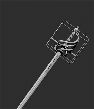
Figure 23.16. I can manipulate the sword's guard by hovering over it with the Mesh Rotate tool until the bounding box appears.
Note
When the Mesh tool is selected, you can use the widget to manipulate meshes as well. The widget manipulates the mesh layer that is selected in either the 3D {Scene} panel or the 3D {Mesh} panel.
You can apply several texture maps to each mesh associated with your object. These texture maps control the color, texture, and highlights of your object. These textures taken together constitute the material associated with a particular mesh. When you have several meshes in a 3D scene, you also have several materials associated with that scene. When you have the 3D {Materials} panel open, you work closely with the Layers panel to make changes to the look of your object.
Figure 23.17 shows the 3D {Materials} panel along with the Layers panel associated with the wine bottle that can be created from the 3D presets. You can see that three textures and three materials are associated with the bottle. This is deceptive, because you might think they are the same thing, but I take you through a couple of exercises to not only demonstrate the difference between them, but show you how you can make changes to them.
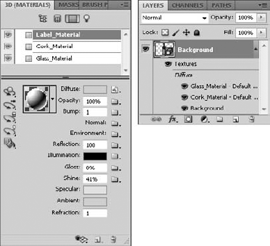
Figure 23.17. The 3D {Materials} panel lists the materials associated with your 3D object, and the Layers panel lists the textures.
Textures are embedded layers in your 3D object. You can edit them by double-clicking the layer in the Layers panel. This brings up the image file used to create the texture. Make changes to the image file and save it. The changes are immediately reflected on your 3D object.
The label on the wine bottle created using the Wine Bottle preset is empty. You can make a custom label by following these steps:
Create a new document in Photoshop.
I created an 11 × 8.5 landscape paper-sized document with a white background.
Double-click the background layer to change it to a regular layer, and change the name of the layer to Label.
Note
It isn't necessary to change the layer from a background layer to create a 3D object, but you want to change the name of this layer.
Use the 3D panel to create a new shape from a preset.
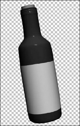
Choose Wine Bottle, and click Create. The wine bottle shape appears, using the white background color for the label and leaving a transparent background, as shown in Figure 23.18. The white background used to create the label is now a sublayer in the 3D object named "Label."
Double-click the Label sublayer.
A new document comes up in Photoshop. It looks just like the document you started with in Step 1.
Place an image file, add text, create shapes, and/or paint to your heart's content.
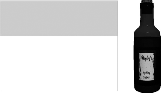
Use all the tools in Photoshop to create a fabulous label. You can see mine in Figure 23.19.
Use Ctrl/

You can close the label file, or just click the tab of your 3D file to return to it. You see your new label wrapped around the bottle, as shown in Figure 23.20.

Tip
You probably want to leave the label file open long enough to make sure it looks the way you want it to. After all, it looks different on the bottle than it does as a flat document.

You can continue to make changes to the bottle by making changes to the bottle and cork textures. When you open these files, you might be surprised to see that they are completely transparent; there is no color information at all. That's because their color and texture are being created in the 3D {Materials} panel. I show you how in the next section.
Even with a nice label applied, the wine bottle is still a little flat and in need of work. The cork and bottle both get their color from the material settings in the 3D {Material} panel. If you select the cork layer, you see that material settings are already applied to it. We could open the texture layer to apply a cork texture, but let's see if we can't make it look good just using the materials settings.
Change the material settings by following these steps:
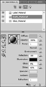
Select the cork Material layer from the 3D {Materials} panel.
You see the material settings change to reflect the cork's settings, as shown in Figure 23.21.
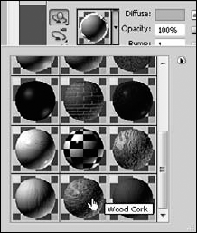
Click the material picker to open it, as shown in Figure 23.22, and find thumbnails of available material presets. Choose Wood Cork, and then click anywhere else to close the material picker.
The settings all change to reflect the wood cork presets. The cork already looks 100 percent better!
Select the Glass_Material layer.
Again the settings change. There is no preset in the materials picker that fits the bill here, so you have to create your own.
Change the settings of the Glass materials.
You can change the following settings:
Diffuse: You can see in the Layers panel that Diffuse is the heading that all the textures are placed under. The diffuse texture is the primary color or texture of the selected material. The diffuse texture of the bottle is green, but the diffuse texture of the label is the one you created. You can click the Edit the Diffuse Texture icon next to the diffuse color and choose Open Texture to open the texture file, just as you did from the Layers panel, and edit it. Change the color of your bottle to a deeper green.
Opacity: This changes the opacity of the material. You can set a universal opacity by using the slider, or you can load or create an opacity map. An opacity map uses grayscale values to determine the opacity of the materials. White creates 100 percent opacity and black is completely translucent, with different shades of gray being everything in between. By creating the opacity map shown in Figure 23.23, I can change the opacity of the top of the bottle, making it look a little more like translucent glass while giving it the appearance of only being partially full of liquid.
Note
Most of these options have icons to the right that allow you to edit that option. If the icon looks like a folder, a map has not been applied. If the icon looks like a document, a map has been applied. Clicking this icon gives you a list of options to create, load, edit, or delete the applied map.
Tip
When you create a new map for any one of these settings, make it the same size as the object you are mapping it to so you can be sure to can get specific details correct. The document that I created my wine bottle from was the Default Photoshop size, for example, so I can create my maps to be the same size.
Bump: You also can use grayscale values to create a bump map that simulates texture on your object. You don't want to add one of these to the glass material, but if you select the Cork_Material layer again and open the bump texture, you see the texture shown in Figure 23.24.
Normal: A Normal map is a texture map that simulates texture just like the bump map, but it is much more versatile because it is based on the RGB values rather than just grayscale values.
Environment: The Environment map is placed as a spherical panorama of the environment around the object. You don't actually see the Environment map around the object though; instead you see a reflection of the environment in any areas of your image that are reflective.
Reflection: This setting determines the reflectivity of your object. The glass is highly reflective, so it is set by default to 100. You also can apply Reflection maps to your object to make some areas more reflective than others.
Illumination: You can create an inner glow with the Illumination setting. Click the color to change the color of the light. Black creates no illumination whatsoever, and white makes your object glow so brightly that it's transparent. This is the perfect setting to add color to the liquid in the bottle. By cutting and pasting the Opacity map and changing the upper color to a dark gray and the bottom color to a deep burgundy, as shown in Figure 23.25, I can deepen the color of the liquid in the bottle and make it look more realistic.
Gloss: You can add glossiness to your object to make it look smooth and add reflectivity. The default on the glass is 59 percent, and that is just about right, because a higher value gives it a solid, plastic look. You can add a Gloss map with this setting.
Shine: The Shine setting determines how sharp the highlights are on the object. A shininess of 100 percent creates the sharp, clean highlights characteristic of glass. The shine also can be applied to specified areas using a grayscale map.
Specular: This setting determines the color of the specular highlights on your object. The specular highlights are the areas that are so reflective, they don't contain color information. These highlights are shown only in the color that you choose, not in any of the other colors placed in the materials of your object.
Ambient: This setting sets the color of the ambient light. This isn't a dramatic change, but it can give your object a warmer or cooler look or slightly change the color.
Refraction: Refraction changes the way light refracts through your scene. A setting of 1 approximates the refraction you get when light passes through air. You see a difference in this setting only when you are rendering a ray traced scene.


The Material Drop tool is found at the bottom of the tools in the 3D panel. It looks very similar to the Paint Bucket tool and works very similarly as well. Click the Material Drop tool to activate it and change the options bar. The options bar for the Material Drop tool is very simple; it's a drop-down menu with the material presets and a Load Selected button to load the selected material into the bucket. Use the drop-down menu to choose a material preset, hit the Load Selected button, and use the bucket to hover over your 3D scene. The different meshes in your scene are highlighted as you hover over them. Simply click to fill a highlighted mesh with the selected material.
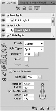
The last filter in the 3D panel opens the 3D {Lights} panel shown in Figure 23.26. Whether you create a model in Photoshop or import a model from another source, Photoshop places default infinite lights in your scene. Without these lights, you can't see the details of your object; it would appear very dark.
Besides the infinite lights, you can add three other types of light to your scene: point lights, spot lights, and image-based lights. Each type of light is contained in its own group in the light layers. As you add additional lights, they appear under their particular light group. You can select a light to make changes to it or double-click it to change its name.
Before you start adding and adjusting the lights in your scene, you should turn on the light guides so you can see your light sources and types. Click the Toggle misc 3D Extras icon at the bottom of the 3D panel, and select lights. The light sources appear in your view of the 3D object, as shown in Figure 23.27.

Adding a new light is as simple as clicking the Add New Light icon at the bottom of the 3D panel. A drop-down list appears, as shown in Figure 23.28, and you can choose the type of light you want to add. With the light visibility turned on, the light guides appear as you create each light, as seen in Figure 23.29. These are the types of light you can choose from:
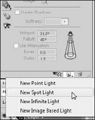

Point light: This type of light radiates light in all directions from the light placement, the same effect as a light bulb would have on a scene. Objects and surfaces that are closer to the light are brighter than those that are farther away. You can move a point light anywhere in your scene using the Light tools, but because it is pointless to rotate it, that option is not available.
Spot light: This type of light creates a light that can be pointed in a specific direction. The light emanates in a conical shape from the source, so the closer the object is to the light, the tighter and more concentrated the light is.
Infinite light: Infinite lights radiate light uniformly from a single plane toward your 3D scene. They simulate the sun shining from a specific direction. Like the sun, infinite lights have a consistent intensity, so any surface that is hit directly by this light is lit with the same intensity, even if the surfaces are different distances from the light source. You can rotate infinite lights around your 3D scene.
Image-based light: These lights are a new addition to CS5. They allow you to use an image to create a light source. You can see in Figure 23.29 that the image is wrapped around the entire scene in a spherical panorama. The best images to use for a more dramatic effect are 32-bit HDR images, but any image works. To activate this light, you have to create a new image after adding the light. Use the image folder in the light settings to do this.
After you have created lights, you can manipulate and move them around your scene so you can create the lighting effects you want. The lights are positioned with the Light tool in the 3D panel, just like the objects, cameras, and meshes, with a couple of new tools added in.
Tip
It is extremely important that you position your object the way you want it to look before you take too much time positioning your lights. When you move your object, your lights stay where they were placed, changing the light settings on the object. If you do want to view your object from a different angle without changing the light settings, use the Camera tool to change your view of the object. This creates the illusion of changing the position of the object as well as the lights.
When you click the Light Rotate tool in the 3D panel, the options bar changes to reflect the tools available to you in moving the lights in your scene, as seen in Figure 23.30. As you click different types of light, the tools highlight if they can be used with that light. A spot light is the only light that can be moved with all the available tools, a point light can't be rotated, and the infinite and image-based lights can only be rotated, not moved using the drag or scale options.

Photoshop includes two new options for lights:
Point Light at Origin: Use the Point Light at Origin button to rotate the light in place so it is pointed directly at the center of your 3D scene.
Move to Current View: Use the Move to Current View button to move the light to the exact position of the camera you are using to look at the scene, showing the source of the light and illuminating the face closest to you.
These tools also are available in the 3D panel when a specific light is highlighted in the light layers.
Using presets or with a light layer selected, you can change the light setting in the 3D {Lights} panel. These settings are available to you:
Preset: From the Preset menu, you can choose a lighting preset that imitates everything from the soft lights of dawn to the exciting, colored lights of Mardi Gras. You also can create your own light settings and add them to the presets using the Save Lights Preset option in the 3D panel menu.
Light type: You can change a selected light from its current type to any other type of light using this option. For instance, if you have an infinite light selected, you can change it to a spot light using this option.
Intensity: This option increases the intensity or brightness of the selected light. The default settings for newly created lights are fairly low. If you want to get a strong lighting effect, increase the intensity. Use the drop-down slider, or click the name to use the scrubby slider.
Color: Double-click the color box to open the Select Light Color dialog box, and choose any color you like for the color of your lights. Obviously, changing the color of your light greatly affects the look of the color of the materials applied to your object.
Image: The Image folder is used with the imaged-based light to load and edit the image that will be used for this light. It works just like the different maps that were applied in the 3D {Materials} panel.
Create Shadows: Select this option if you want a selected light to cause your objects to cast shadows in your 3D scene. If you have multiple lights applied to a scene, you may want only one or two to actually cast shadows so you don't have a scene busy with them. Remember that you will only see shadows if your 3D preferences are set to Ray Tracer.
Softness: This option lets you choose how diffuse the shadow of a selected light is.
Hotspot and Falloff: These options are used with spot lights to determine how large the bright center of the light is and how fast that center falls off to no light at all. Higher values in these areas create a larger spot light that fades abruptly.
Use Attenuation: You can use attenuation settings with both spot lights and point lights. When you turn this option on, the intensity of these lights diminishes with distance.
Inner and Outer: Used in conjunction with the Use Attenuation setting, the Inner and Outer settings determine how much the intensity changes with distance.
This chapter covered most of the changes you can make to the look of your 3D object with the 3D settings. The 3D panel is an incredibly versatile tool that allows you to make many different kinds of changes to several aspects of your 3D scene, giving you lots of creative potential in changing the look of your 3D scene. You learned about the following:
The 3D panel
Changing 3D preferences
Rendering your 3D scenes
Changing the meshes on your 3D objects
Editing and adding new materials to your 3D objects
Adding and changing the lights in a 3D scene