Although polygon-based meshes tend to be the bread and butter of modelers in Blender, they aren't the only types of objects that are available to you for creating things in 3D space. Blender also has curves, surfaces, meta objects, and text objects. These objects tend to have somewhat more specialized purposes than meshes, but when you need what they provide, they're extremely useful.
Curves and surfaces are nearly as general-purpose as meshes, but they're particularly handy for anything that needs to have a smooth, non-faceted look. They're also important for models that require mathematical precision and accuracy in their appearance. Meta objects are great at creating organic shapes that merge into one another, such as simple fluids. You can also use them to make a roughly sculpted model from basic elements if you don't want to work in Sculpt mode. Text objects are exactly what they sound like: You use them to add text to a scene and manipulate that text in all three dimensions. This chapter tells you more about working with all of these types of objects.
So, what's the biggest difference between curves and surfaces when compared to meshes? Math! Okay, I'm sorry. That was mean of me; I know that math can be a four-letter word for many artists. Don't worry, you won't have to do any math here. What I mean to say is that curves and surfaces can be described to the computer with a mathematical function. Meshes, on the other hand, are described with all of the individual vertices that they're composed of. This means that, in terms of the computer, curves and surfaces have two advantages:
They are very precise. When you get down to it, the best that a mesh can be is an approximation of a real object. It can look really, really good, but it's not exact. Because curves are defined by math, they are exactly the correct shape. This is why designers and engineers like them. In fact, they're used as the reference for creating real objects. (So real objects are actually approximations of the curve design!)
They take up less memory. Because the shape is mathematically defined, the computer can save that shape by saving the math, rather than saving all of the individual points. This means that complicated curves and surfaces usually take up quite a bit less space than the same shape made with meshes.
Of course, there are some caveats to these advantages. For one, curves and surfaces can sometimes be more difficult to control. Since curves and surfaces don't really have vertices for you to directly manipulate; you have to use control points. Depending on the type of curve, control points can sit directly on the shape, or float somewhere off of the surface as part of a control cage.
Another thing to bear in mind is that even though curves and surfaces are perfect mathematical descriptions of a shape, the computer is actually an imperfect way of displaying those perfect shapes. At the beginning of Chapter 5, I mentioned that all 3D geometry is eventually tessellated, or turned into a mesh of triangles, when the computer processes it. This means that even though curves and surfaces can take less memory on a computer, displaying them smoothly may actually take more time for the computer to process. To speed things up, you can tell the computer to use a rougher tessellation with fewer triangles. This means that what you see in Blender is an approximation of that perfect curve or surface shape. Do you find yourself thinking, "But hey, I thought curves were supposed to be perfect mathematical descriptions of a shape. What gives with these facets?" Well, the curve is perfect. It's just hard for the computer to show it to you directly.
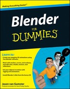
But despite these minor disadvantages, using curves and surfaces is a really smart move in quite a few cases. For example, most designers like to use curves for company logos because curves can scale in print to any size without looking jagged or aliased around its edges. What this means to you as a 3D artist is that you can import the curves of a logo design and give the logo some depth, dimension, and perhaps even some animation. Speaking of animation, curves have quite a few handy uses there as well. For instance, you can use a curve to define a path for an object to move along. Curves are also used in Blenders Ipo Curve Editor to graph and control the changes to an object's properties over time. For modeling purposes, curves are great for pipes, wires, and ornate organic shapes. Figure 6-1 shows a park bench. I used only curves to model its sides.
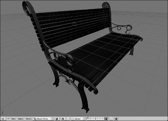
Figure 6-1. With the exception of the slats for the seat and back, this entire park bench was modeled with curves.
A set of curves used to define a shape in three dimensions is a surface. In some ways, curve surfaces are very similar to the subdivision surfaces on meshes that have the Subsurf modifier because they both have a control cage that defines the final shape that's created. The difference is that the curve surface has space and precision benefits that meshes don't have. Also, surfaces are a little bit easier to add textures to because you don't have to go through the additional step of unwrapping, or flattening the surface so a two-dimension texture can be applied to it. When you use a surface, you get that unwrapping for free because it's already done for you.
Note
For these reasons — especially the precision — architects, industrial designers, and engineers prefer to work with surfaces on their models. Just about everything in your house was designed by someone. That includes your water faucet, your coffee maker, your television, your car, and even the house itself. If it was manufactured within the last 20 years, chances are good that it was designed on a computer and visualized with surfaces. Also, before the advent of subdivision surfaces on meshes, early characters for computer animations were modeled using curve surfaces because they were better at achieving organic shapes. Of course, if you're seen using curves to build a character these days, you might be viewed as a bit of masochist ... especially if you try to do it in Blender. I go into why a little bit later in this chapter.
In Blender, you can add curves by using Spacebar

NURBS stands for Non-Uniform Relational B-Spline. The control points in NURBS curves don't have handles like Bézier curves do. In fact, by default, NURBS control points don't normally even touch the curve shape itself. Instead, the control points are weighted to influence the shape of the curve. Control points with higher weights attract the curve closer to them. Figure 6-3 shows the same curve shape made with Bézier curves and with NURBS curves.

Warning
One thing to keep in mind is that although curves can work in three dimensions and can even create three-dimensional shapes like the park bench in Figure 6-1, they cannot be extruded to create a surface. If you want to create a surface, you need to actually navigate to the Surfaces menu (Spacebar

Surprisingly few specialized controls are specific to curves. Grab (G), Rotate (R), and Scale (S) work as expected and, like with meshes, you can Extrude a selected control point in Edit mode by either pressing E or Ctrl+left-clicking where you would like to extrude to. Joining separate curves in Edit mode can be done by selecting the end control points on each curve and pressing F, like making a face with meshes.
One place this doesn't work, however, is if the two control points you select are on the same curve. For something like that, you're probably wanting to close the curve, or, in Blenderese, you want to make the curve cyclic. To do this, press C while in Edit mode. Figure 6-5 shows a cyclic (closed) and non-cyclic (open) Bézier curve.
Note
If you make a 2D curve cyclic, it creates a flat plane in the shape of your curve. And putting one cyclic curve within the borders of another actually creates a hole in that plane. However, this does not work with 3D curves because they aren't planar. In those situations, you want to use a surface.

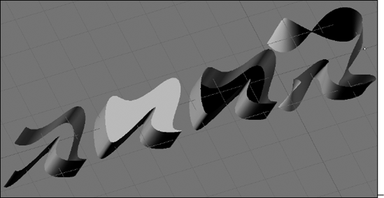
Curves are initially set to work only in two dimensions by default. It can be any arbitrary two-dimensional plane you want, but the control points are constrained to the curve object's local XY plane. To allow the curve to work in three dimensions, go to the Curve and Surface panel in the Editing buttons (F9), as shown in Figure 6-6, and left-click the 3D button. When you enable 3D on the curve, you might notice that in Edit mode, the curve now has little arrows spaced along it. These arrows indicate the direction of the curve. All curves have direction, even cyclic ones. Normally this isn't all that important except for when you are using the curve as a path. In that situation, the direction of the curve is the direction that the animated object is traveling along the curve. Switching the direction of the curve can be done by going to Curve

The buttons in the Curve and Surface panel are relevant to all curves, regardless of type. Some of the most important ones are in the right-hand column of buttons. First up are the DefResolU and RenResolU values. These values define the resolution of the curve. Remember that Blender only shows you an approximation of the real curve. Increasing the resolution here makes the curve look more like the curve defined by the math, at the cost of more processor time. That's why there are two resolution values. DefResolU is the default resolution and it's what you see in the 3D View. RenResolU is the resolution that Blender uses when you render. By default, this is set to zero, which means Blender uses whatever value that is in DefResolU.
With the exceptions of the 3D button – which I've already covered – and Width, the rest of the buttons in this column pertain to extruding and beveling your curve objects. Width is pretty interesting because it allows you to offset the curve from the control points. This is most apparent (and helpful) on cyclic curves. Values less than one are inset from the control points, whereas values greater than one are outset. (This is a quick way to put an outline on a logo or text because Blender does not have a stroke function for curves as do Inkscape or Adobe Illustrator.)
The Extrude value is probably the quickest way to give some depth to a curve, especially a 2D curve. However, you don't want to confuse this with the extrude capability you get by pressing E. This value affects the entire curve in Object mode, rather than just the selected control points in Edit mode. On a cyclic 2D curve, the flat planar shape that gets created extends out in the local Z direction of the curve object, with the caps drawn on it. And you can even control whether Blender draws the front or back cap by enabling or disabling the Front and Back buttons on the Curve and Surface panel. If you extrude a non-cyclic curve, you end up with something that looks more like a ribbon going along the shape of the curve. This is also what happens when you increase the extrude value on a 3D curve. Figure 6-7 shows some of the different effects you can get with an extruded curve.
Of course, one of the drawbacks to extruding a curve is that you get a really sharp edge at the corners of the extrusion. Depending on what you're creating, harsh edges tend to look "too perfect" and unnatural. Fortunately, we have Bevel to take care of that for us. To give an extruded curve more natural corners, simply increase the Bevel Depth value. You may notice that when you do this, the bevel is really kind of simple: just a cut across the corner. Say you want that to be even smoother. You can make that happen by increasing the BevResol value. Like the DefResolU and RenResolU values, this value increases the resolution of part of the curve. In this case, it's the resolution of the bevel. Increasing the BevResol value makes a smoother, more curved bevel. This works on both cyclic and non-cyclic curves.
But say you want something more ornate, kind of like the molding or trim you'd find around the doorway on a house. For that, you want to use a BevOb, or Bevel Object. This basically means that you're going to use the shape of one curve to define the bevel on another. To get a better idea of what I'm talking about, use the following steps:
Create a Bézier circle (Spacebar

Scale up nice and large with S so you can see what's going on.
Extrude the circle by increasing the Extrude value in the Curve and Surface panel of the Editing buttons (F9).
The circle doesn't have to be excessively thick, just enough to give it some form of depth.
Create a Bézier curve (spacebar
Tab into Edit mode and edit this curve a bit to get the bevel shape that you want. Keep the curve non-cyclic for now. When you're done editing, tab back out to Object mode.
Select your Bézier circle and, in the BevOb field of the Curve and Surface panel in the Editing buttons, type in the name of your Bézier curve.
If you didn't rename it, it's probably called something like Curve or Curve.001. After you confirm this by pressing Enter, the corners of your Bézier circle are beveled with the shape defined by your Bézier curve. Now for fun, follow the next step.
Go back and make the BevOb curve cyclic.
Doing so actually removes the front and back planes from the extrusion. You're left with a curve shape that follows the main Bézier circle's path. For extra kicks, select the Bézier circle and Tab into Edit mode. Select any control point and press Alt+S to shrink or fatten the beveled shape around that control point. Slick, huh?
Note
When you use a BevOb, you're essentially handing control of the curve's shape over to the BevOb object. That being the case, after you do it changing the values for Extrude, Bevel Depth, and BevResol has no effect on the curve for as long as you have the BevOb there.
Figure 6-8 shows the results of these steps.

Tip
If you're using a curve to model anything roughly cylindrical in shape such as a pipe or a tube, there's actually no need to use a BevOb curve. It's a bit of a hidden function, but you can get the same effect by beveling the curve. I know that sounds odd (how do you bevel something that doesn't have any corners?), but trust me, it works. You do it by disabling both the Front and Back buttons in the Curve and Surface panel and then increasing the Bevel Depth. Increasing the BevResol value makes the cross-section more circular. Hooray! One less BevOb object to hide!
In the preceding example, I showed you that Alt+S can be used on individual control points to shrink or fatten the thickness of the extrusion. However, perhaps you would like to have more control than that along the length of the curve. This is where you would use the TaperOb field. Like the BevOb field, the TaperOb field uses one curve to define the shape of another. In this case, you're controlling the thickness along the length of the curve, and it works in very much the same way: Create a separate curve that dictates the taper shape and then type the name of that curve in the TaperOb field of the curve you'd like to control. Figure 6-9 shows how a TaperOb can give you complete control of a curve's shape along its length.
Tip
I prefer to create my BevOb and TaperOb curves in the Top view (Numpad 7) along the X-axis. This way, I have a good frame of reference of where the center line of the curve is. That's important because BevObs use the center line to define the front and back of a curve's extrusion. And you can think of TaperObs as a kind of profile that revolves around its local X-axis. Bringing your control points to the center line makes the tapered curve come to a point, whereas moving them away from the center line increases the thickness there.
One other thing that you can control on curves is the tilt of the control points. In other programs, this might be called the twist property. To get a good idea of what you can do with tilt, try the following steps:
Create a Bézier Curve (Spacebar
Make the curve cyclic (C).
You may also want to select (right-click) the handles and rotate (R) them so there's a cleaner arc.
Enable 3D on the curve (F9
Select one of the handles and press T.
When you do this, move your mouse cursor around the point in a clockwise fashion. While you do that, watch how the Tilt value in the 3D view's header changes.
Confirm completion (left-click or Enter).
If you increase the Extrude and Bevel Depth values, you should now have something that looks a bit like Figure 6-10.
The most defining aspect of Bézier curves are the handles on their control points. Handles on Bézier curves are always tangential to the curve and come in one of four varieties in Blender:
Aligned (H – toggles with Free): Aligned handles are always in a straight line and they display in a pinkish color. If you grab (G) and move one handle on a control point, the other moves in the opposite direction to balance it out. You can, however have aligned handles of differing lengths.
Free (H – toggles with Aligned): Free handles are sometimes referred to as "broken" handles. They display in black and don't necessarily have to be in a straight line. They are best suited for giving you sharp points that smoothly flow to the next control point.
Auto (Shift+H): These handles are set by Blender to give you the smoothest possible result in the shape of your curve. They show up in yellow and generally form a straight line with equal lengths on either side. If you try to edit an Auto handle, it immediately reverts to an aligned handle.
Vector (V): Vector handles are broken like free handles, but they point directly to the next control point. This makes the shape of the curve an exactly straight line from one control point to the next. Editing the handles on a vector control point turns it into a free handle.
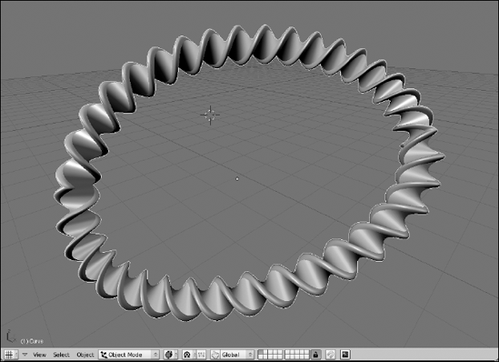
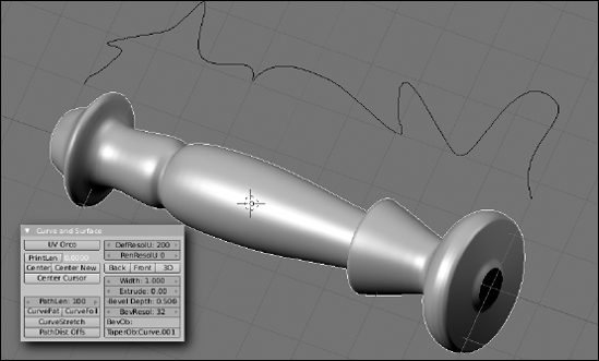
Figure 6-11 shows four curves with the same exact control points, but with different types of handles. And, yes, you can mix handle types in a single curve. It's actually quite handy when you need a figure to be smooth in some parts and pointy in others.
NURBS are a different kind of beast in terms of controls. They have control points, but NURBS curves are conspicuously without handles. Now, remember that Blender treats a NURBS curve differently than a NURBS surface curve. With that in mind, though, whether you're dealing with a curve or a surface curve, the following things generally apply to all NURBS:
Each control point has a weight. The weight, which is a value between 0 and 1, influences how much that control point influences the curve. In Blender, you set the weight with the buttons at the bottom of the Curve Tools panel (see Figure 6-6 for reference). You can explicitly type the weight in the Weight field, or left-click one of the buttons near it to give it a preset value. After you decide the weight you want, left-click the Set Weight button. The value in the Weight field is applied to all selected control points.
NURBS have knots. In math terms, knots are vectors that describe how the resulting curve is influenced by the control points. In Blender, you have three settings that you can assign to knots from the Curve Tools panel: Uniform, Endpoint, and Bézier. By default, NURBS are assigned uniform knots. You can tell this because the curve does not go all the way to the end control points. Those control points' weights are factored in with all of the others. Endpoint knots, in contrast, bring the curve all the way to the last control points, regardless of weight. Bézier knots treat the control points like they are free handles on a Bézier curve. Every three control points act like the center and two handles on a Bézier curve's control points.
NURBS have an order. An order is another math thing. What it really means, though, is that the lower the order, the more the curve directly follows the lines between control points. And the higher the order, the smoother and more fluid the curve is as it passes the control points. The values for order can also be changed in the Curve Tools panel.
Figure 6-12 shows the influences that curve weights, knot types, and order can have on a NURBS curve.
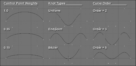
Figure 6-12. Decreasing curve weights on a control point, differences between the three knot types, and increasing the order of a curve.
Warning
After you set the weight of a control point or a knot type, you can always set it to another value. However, there's currently no easy way to find out what weight each control point has or what type of knot the curve is using (although the latter is pretty easy to guess visually). So keep in mind that on a complex NURBS object, you might lose track of your weights.
You might notice in the Curve Tools panel that the knot, order, and resolution controls can each be independently set for a U or a V value. If you're dealing with just a curve, the U direction is all you need to worry about. However, a NURBS surface works in two directions: U and V. If you add a NURBS Surface (Spacebar
One of the really cool things that you can do easily with NURBS surfaces that's difficult to do with other types of surfaces is a process called lofting. (Other programs might call it skinning, but because that term actually means something else for rigging, I use lofting here.) Basically, lofting is the process of using a series of NURBS surface curves with the same number of control points as a series of profiles to define a shape. The cool thing about doing it in Blender is that after you have the profiles in place, it's as simple as selecting all control points (A) and pressing (F). The classic use for this is modeling the hull of a boat, as you see in the following steps and Figure 6-13:
Add a NURBS surface curve (Spacebar
Select All and Rotate −90 degrees around the X-axis (A
This forms the bottom of your boat.
Model a cross-section of the boat's hull. Add more control points using Extrude (E or Ctrl+left-click) and move them around with Grab (G). When doing this, it would be a good idea to press C and make the curve cyclic.
Try to keep the cross section as planar as possible. I like to work on this from the front view (Numpad 1).
Select all control points in your cross section and duplicate it along the Y-axis (A
Make adjustments to the new cross section to suit your tastes, but do not add any control points.
Lofting requires that each cross-section has the exact same number of control points. If you add or remove control points from a cross-section, it doesn't work.
Repeat steps 4 and 5 until you're satisfied.
Select All and press F.
Congratulations! You've made a canoe!

When compared to other tools that work with NURBS surface, Blender admittedly falls short in some functions. You can extrude surface endpoints, do lofting, and even spin surface curves (sometimes called lathing in other programs) to create bowl or cup shapes. However, that's about it. Blender currently doesn't have the functionality to do a ton of other cool things that can be done with NURBS surfaces, such as using one curve to trim the length of another or project the shape of one curve onto the surface of another. These are things that you cannot currently do with Blender's NURBS surfaces.
However, there's actually hope. It's been slow coming, but there's recently been more progress on the integration of better NURBS tools within Blender. If you're curious about this, do a Web search for "Blender and Nurbana" to see how progress is coming. If all goes well, the next version of Blender should show marked improvement. Ultimately, NURBS may even be able to use a large quantity of the modifiers that we enjoy using on meshes.
Meta objects are cool little 3D surfaces that have been part of computer graphics for a long time. Sometimes they are referred to as blobbies. The principle behind them is pretty simple: Imagine that you have two droplets of water and you begin moving these two droplets closer and closer to each other. Eventually, the two droplets are going to merge and become a single, larger droplet. That's basically how meta objects work, except you have complete control over when the droplets merge, how much they merge, and you can re-separate them again if you'd like. You can also do something that's more difficult in the real world: You can subtract one droplet from the other, rather than add them together into a merged object. They're a ton of fun to play with and there are some pretty neat applications for them. Figure 6-14 shows two metaballs being merged.

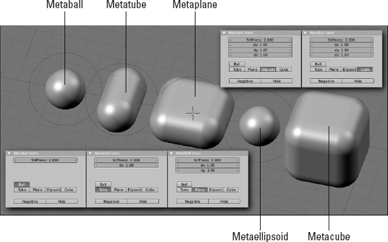
Meta objects are a bit like curves and NURBS in that their entire existence is defined by math. However, unlike NURBS or even meshes, you cannot control the surface of a meta object directly with control points or vertices. Instead, the shape of their surface is defined by a combination of the object's underlying structure – a point, a line, a plane, a sphere, or a cube – and its proximity to other meta objects. There are five meta object primitives:
Metaball: The surface in this primitive is based on the points that are all the same distance from a single center point. This means that you can move and scale a metaball uniformly, but you cannot scale it in just one direction.
Metatube: Whereas the basis for a metaball is a single point, the basis for a metatube is the line between two points. This means that you can scale the surface uniformly, like a metaball, but you can also scale it in its local X-axis, referred to as dx.
Metaplane: The metaplane's underlying structure is, as you may have guessed, a plane. This means you have both the local X (dx) and the local Y (dy) axis for scaling, as well as scaling uniformly.
Metaellipsoid: At first glance, you might mistake this meta object for a metaball. However, instead of being based on a single point, this object is based on a sphere. So if you keep the local X, Y, and Z dimensions equal, it behaves just like a metaball. However, you also have the flexibility to allow you to scale in any of the three individual axes.
Metacube: The metacube is like the metaellipse in that it's also based on a three-dimensional structure. In the metacube's case, it's a cube rather than a sphere.
One of the coolest things about meta objects is that you can change from one primitive to another on the fly using the MetaBall Tools panel in the Editing buttons (F9). Figure 6-15 shows each of the primitives along with the default settings for them in the MetaBall Tools panel.
The MetaBall Tools panel appears when you tab into Edit mode on a meta object. The panel always displays the Stiffness value for the selected object. This value controls the influence that the selected meta object has on other meta objects. It's indicated visually in the 3D View with a green ring around the meta object's center point. You can adjust the Stiffness value here in the panel or, if you select the green ring (right-click), you can Scale (S) to adjust the Stiffness visually. By right-clicking the pinkish ring outside of that green ring, you can select the actual individual meta object.
And depending on the type of meta object primitive you're using, other values of dx, dy, and dz may appear in the MetaBall Tools panel. You can adjust these values here or in 3D View by using the S
When you Tab back out to Object mode, you can move your combined meta object (a meta-meta object?) as a single unit. Note, however, that even though you've grouped these meta objects into a single Blender object, they don't live in a vacuum. If you have two complex Blender objects made up of metas, bringing the two of them together actually causes them to merge. Just something you may want to keep in mind and take advantage of in the future.
As a single Blender object, though, there are a few more things that you can control using the MetaBall panel, shown in Figure 6-16. This panel is always available to meta objects, whether in Object mode or Edit mode, and it normally sits to the right of the Link and Materials panel.

The first two values in the MetaBall panel are Wiresize and Rendersize. Wiresize controls how dense the generated mesh is for the meta object in the 3D view. Lower values are a finer mesh, whereas higher values result in much more of an approximation. The Rendersize value does the same thing, except it only has an effect at render time. The reason for this is that meta objects can get really complex quickly and, because they're generated entirely by math, these complex combinations of meta objects tend to use a lot of computer processing power. Working at a larger wiresize in the 3D view helps keep your computer responsive while you work, whereas a finer Rendersize value keeps things pretty on output.
Note
The Threshold value is an overall control for how much influence the metas in a single Blender object have over each other. This value has a range from zero to five, but in order for a meta object to be visible, it's individual Stiffness value must be greater than the Threshold value.
Below Threshold are four buttons that control how the meta objects get updated and displayed in the 3D View:
Always: The slowest and most accurate setting. This is the default. Every change you make in the 3D View happens instantly (or as fast as your computer can handle it).
Half Res: Enabling this button reduces the resolution of the meta object as you move or edit it to increase the responsiveness of the 3D View. As soon as you finish transforming the meta object, it displays in full resolution again.
Fast: As the name implies, this is nearly the fastest setting. When you enable this button, Blender hides the meta objects when you perform a transform and then re-evaluates the surface when you finish. It works very nicely, but the downside is that you don't get the nice visual feedback that Always and Half Res give you.
Never: This is certainly the fastest update method. Basically, if you try to edit a meta object, it hides everything and never updates in the 3D View. Although this may not seem useful at first, if you decide to bind your meta object to a particle system as a way of faking fluids, turning this setting on definitely increases performance in the 3D View.
Alright, so what in the world can you actually use meta objects to make? There are actually two answers to this question: all sorts of things, and not much. The reason for this seemingly paradoxical answer is that meta objects can be used to do quick, rough prototype models and they can also be used with a particle system to generate simple fluid simulations. However, with the advent of advanced modeling tools like multi-res sculpting and subdivision surfaces, meta objects don't get used as often for prototyping. And with more advanced fluid simulation and rendering technology, meta objects are also used less for those applications as well.
That said, even though meta objects are used less for these purposes, that doesn't mean that they're never used. In fact, not too long ago, I used a set of metaballs with a glowing halo material to animate the life force being forcefully pulled out of a guy. I mean, I could probably have used a particle system or fluid simulator to do it, but using metaballs was actually faster to set up and I had more direct control over where everything was placed on the screen. So don't count meta objects out just yet. There's still some life in these little suckers. Besides, they're still fun to play with!
Over the years, working with text in Blender has come a long, long way. As you might expect, the way you work with text in Blender has quite a few differences from what you might expect of word processing software like OpenOffice.org or Microsoft Word. What you might not expect is that Blender's text objects share a few features in common with desktop publishing programs like Adobe InDesign or QuarkXPress. In fact, one Blender developer even went so far as to create his own version of Blender specifically geared toward desktop publishing. If you're interested in finding out more about it, do a Web search for DTPBlender.
Blender's text objects are really a specialized type of curve object. This means that nearly all of the options I already described for the Curve and Surface panel in the Editing buttons also apply to text. For example, you can quickly bring text objects into the third dimension using the Extrude, Bevel, and even the BevOb and TaperOb fields. Figure 6-17 shows an example of the interesting things you can do with a single text object in Blender.
You add a text object in Blender the same way you would add any other object: with the toolbox. Press Spacebar

Shift+Ctrl+left/right arrow highlights whole words at a time. Backspace deletes text and pressing Enter gives you a new line.
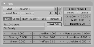
In addition to that, there are formatting controls in the Font panel of the Editing buttons, as shown in Figure 6-18. Two of the coolest buttons here are the Insert Text and Lorem buttons. If you already have a bunch of text created and don't feel like re-typing all of it in Blender, left-click Insert Text and use the File Browser to find the text file you want to load. After you do, the content of whatever is in that text file is added from the location of the text cursor. The Lorem button generates filler text in the form of Latin gibberish, also known as lorem ipsum text. Publishing layout designers use lorem ipsum a lot for defining layout when the actual content is not yet known. I've used this for adding placeholder credits when I didn't know everyone's names and titles.
Note
When you're in Edit mode, notice that pressing Tab doesn't indent your text like you might expect because it's already assigned to getting you back out to Object mode. If you really, really need to use a Tab character, you have to import that from another file or use the third-to-last character in the first row of the Char panel (more on this in the next section, "Changing fonts").
Below the Insert Text and Lorem buttons is a block of alignment buttons to help you align your text relative to the center point of the text object. You have the following options:
Left: Aligns text to the left. The text object's center serves as the left-hand guide for the text.
Center: All text is centered around the text object's center point.
Right: Aligns text to the right. The text object's center serves as the right-hand guide for the text.
Justify: Aligns text both on the left and on the right. If the line is not long enough, Blender adds spacing, or kerning, between individual characters to fill the space. This option requires the use of text frames. (See the next section, "Working with text frames," for more details.
Flush: This works similar to the way Justify does, but with two exceptions. First, if the line is the end of a paragraph, it doesn't force the text to align both sides. And second, Flush uses word spacing rather than kerning to get lines to align properly. Like Justify, this option requires the use of text frames.
ToUpper: This really isn't an alignment button, but it's in the grouping, so it's worth covering here. Left-clicking this button toggles the characters in your text object between all uppercase letters and all lowercase letters.
An important thing to notice is that both the Flush and the Justify options require the use of something called text frames. The Left, Center, and Right align options all work relative to the location of the text object's center. If you want to align your text on both the left and the right side, you need more than one reference point. Text frames are a way of doing this for you, but with a couple of additional benefits as well. Basically, they're a rectangular shape that defines where the text in your text object lives. Text frames are similar to the frames you might use in desktop publishing programs. They're also one of those things that you normally don't see in 3D software.
To work with text frames, you use the block of buttons on the upper right corner of the Font panel. The first button should read "1 TextFrame: 1". This means that you have one text frame in your text object and that's the one you're currently working on. If you left-click the Insert button, the field changes to say "2 TextFrame: 2," meaning you're on the second of two text frames. To go back to the first text frame, left-click the arrow on the left of the TextFrame field or left-click the center of it and type 1 for the value. You can delete the current text frame by left-clicking the Delete button. Of course, having a text frame doesn't mean much if you don't define its size and location. That's what the buttons at the bottom of the block are for. The X and Y fields determine where the top left corner of the text frame is located, whereas the Width and Height fields define its size in Blender units. As you adjust these values while in Edit mode, you should see a dashed rectangle in the 3D View.
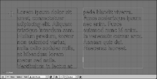
Now, the cool thing about text frames is that if you have more than one defined, the text can overflow from one text frame into the other. This is an excellent way to get very fine control over the placement of your text. You can even do newspaper-style multi-column text this way, as shown in Figure 6-19.
If you're working with a lot of text, you might find that Blender might not perform as speedily as you would like while editing. If you left-click the Fast Edit button in the Font panel, Blender uses just the outline to the text in the 3D View while in Edit mode. This gives Blender a bit of a performance boost so you're not waiting for characters to show up seconds after you finish typing them.
The block of buttons at the bottom of the Font panel control how the text appears in the selected text object. Descriptions of each follow:
Size: Font size on a scale from zero to ten. Adjusting this value should adjust the font size as dictated by the font. This is generally a better way to change the size of your text rather than simply scaling the text object.
Linedist: Line distance, also referred to as leading. This value defines the distance between lines of text in your text object and it also has a range from zero to ten.
Word spacing: Globally defines the space between words in your text object. This field has a range from zero to ten.
Spacing: The global distance between all characters in your text object, also known as tracking. Like the previous fields, it has a range from zero to ten.
Shear: A quick and dirty way to fake italics on a font. Values between 0 and 1 tilt characters to the right, whereas values between −1 and 0 tilt them all to the left.
X offset: Offsets the text object to the left or right of its default position. Values less than zero shift it left, whereas values greater than zero shift it right.
Y offset: Offsets the text object up or down from its default position. Values less than zero shift it down, whereas values greater than zero shift up.
UL position: Determines the position of the underline, if enabled (Ctrl+U on highlighted text). This value has a range from −0.2 to 0.8.
UL height: Controls the thickness of the actual underline, if enabled (Ctrl+U on highlighted text). You can set this value between 0.01 and 0.5.
Note
If you're familiar with typography, you may notice two things right off the bat. First, the terms used here are not the standard typography terminology, and second, the values are not in your typical percentage, point, pica, or pixel sizes. There are two primary reasons for this. First, Blender is a 3D program intended for 3D artists, many of whom may not be familiar with typography terms and sizes. The second reason dovetails with that, but it's a bit more on the practical side. Blender text objects are 3D objects that can be just about any size in virtual 3D space. Sizes like points, pixels, and picas don't really mean anything in 3D because there's not a frame of reference, like the physical size of a printed piece of paper.
Another thing that's different about Blender's text objects is the way it handles fonts. If you're used to other programs, you might expect there to be a drop-down menu that lists all of the fonts installed on your computer with a nice preview of each. Unfortunately, Blender does not currently have that ability. Instead, what you need to do is left-click the Load button and track down the actual font file for the typeface that you would like to use. Below are the standard places you might find fonts on Windows, Mac, and Linux machines:
Windows: C:WindowsFonts
Mac OS: /System/Library/Fonts or /Library/Fonts
Linux: /usr/share/fonts
After you load a font into your .blend file, it's available for you to use whenever you want it from the font drop-down list. You always have Blender's built-in font available as well. Also, notice the button next to the drop-down with the icon that looks like a present. Left-clicking this button packs the font into your .blend file. This way, if you take your .blend file to a different computer that doesn't have the font you need, it's not a problem because it's packed in. If the font is already packed, left-clicking this button unpacks it to your computer's hard drive.
Now you would think that after you have a font loaded, you should be good to go, right? Well, not quite. See, Blender's buttons for bold and italics are kind of unique. They actually load a separate font altogether. The typical use for this would be to load the bold and italics versions of the main font you loaded. However, that's not a complete requirement. You can actually use an entirely different font altogether here. Because technically you can't arbitrarily change fonts in the middle of a text object, this is a good way to get around that. Just make your bold or italics font the other font you want to use! Figure 6-20 shows this in action. The way you assign a font to either bold, italics, or even both is pretty straightforward:

Figure 6-20. Using the bold and italics fonts to use widely different fonts in a single text object.
You may find that while you're typing, you need certain special characters like the copyright symbol or the upside-down question mark for sentences written in Spanish. For these situations, you have three options:
If the special character is common, you may find it in Text
You can memorize the hotkey combination for various commonly used special characters as listed in Blender's online documentation.
If the character is rare or just not in the menu, you can find it using the box in the Char panel of the Editing buttons (F9). The Char panel has a grid that displays all of the characters in the font that Blender recognizes.
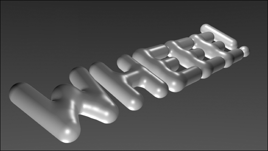
Another unique feature that Blender's text objects have is the ability to use any other Blender object as a font character. So if you want to use Suzanne the monkey every time the uppercase S character is used, you can actually do that. If you want to model letters with meta objects and spell something with them, like in Figure 6-21, you can! It's all done with the Ob Family field in the Font panel. Just use the following steps:
Type the name of your font "family" in Ob Family.
This can be any name you'd like. I like to end it with a dot so I can differentiate my characters later. For example, you may use "MetaLetter." (ending in the period) in this case.
Model a character you wish to use.
In this example, I'm using meta objects, so I would use Spacebar
Name this object with the family name plus the character it will represent.
In this case, if you modeled an uppercase W, you would call it "MetaLetter.W." A lowercase W would be "MetaLetter.w." Now you see why we used the dot at the end of the family name in step 1. It helps keep things organized.
Repeat steps 2 and 3 for each character you need.
Select (right-click) your text object and turn on Dupliverts (F7
Adjust size and spacing to fit. And poof! You've got metaletters!
Now to finish, move the original font text to another layer so it's out of the way of your metaletters.
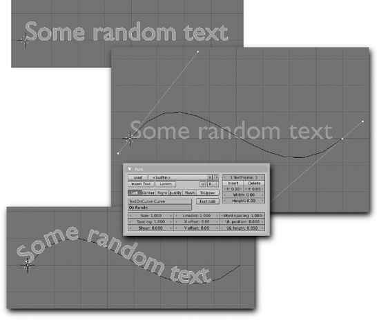
One of the other really powerful things you can do with Blender's text objects is to have the text flow along the length of a curve. This way, you can get text that arcs over a doorway or wraps around a bowl or just looks all kinds of funky. The key to this feature is the TextOnCurve field in the Font panel. To see how this works, use the steps in the following example:
Create a text object (Spacebar
Feel free to populate it with whatever content you would like.
Create a curve to dictate the text shape (Spacebar
This example uses a Bézier curve, but a NURBS curve works fine as well. Also, I like to make my curve with the same center point location as my text object. Granted, that's just my preference, but it works nicely for keeping everything easily manageable.
Select (right-click) the text object and type the name of the control curve in the TextOnCurve field.
Blam! The text should now follow the arc of the curve. If you select (right-click) the curve and tab into Edit mode, any change you make to it updates your text object live.
Figure 6-22 shows 3D text along a curve.
One thing to note is that you should keep your curve as a 2D curve. Because the text is technically a special type of 2D curve, trying to get it to deform along a 3D curve won't work. For that, you're going to need to convert the text into a mesh, as described in the next section.
Of course, while Blender's text objects are pretty powerful, curves and meshes just do some things better. Fortunately, you don't have to model your type unless you really, really want to. Instead, you can convert your text object into a curve or a mesh by pressing Alt+C and choosing Curve, Curve (Single Filling Group), or Mesh. If you're curious as to some specific cases why you'd want to do this, here are a few:
Custom editing the characters for a logo or a specific shape (convert to a curve).
You need to share your .blend file, but the license of your font prevents you from legally packing it into the .blend (convert to a curve).
Getting extruded text to follow a 3D curve (convert to a mesh).
Rigging the letters to be animated with an armature (convert to a mesh).
Using the letters as obstacles in a fluid simulation (convert to a mesh).
Using the letters to generate a particle system (convert to a mesh).
Tip
Using Alt+C also works on curve objects, surfaces, and meta objects to convert them to meshes. Just be aware that most of these conversions are permanent. You can't go back on them without using the undo function.