Working with vertices
Using modifiers such as Mirror, Subsurf, and Array
Sculpting meshes to have extremely high detail
Polygon-based meshes are at the core of nearly every computer-generated 3D animation from video games to television commercials to feature-length films. Computers typically handle meshes more quickly than other types of 3D objects like NURBS or metaballs, and meshes are generally a lot easier to control. In fact, when it comes down to it, even NURBS and metaballs are converted to a mesh of triangles — a process called tesselation — when the computer hardware processes them.
For these reasons, meshes are the primary foundation for most of Blender's functionality. Whether you're building a small scene, creating a character for animation, or simulating water pouring into a sink, you'll ultimately be working with meshes. Working with meshes can get a bit daunting if you're not careful, because you have to control each vertex that makes up your mesh. The more complex the mesh, the more vertices you have to keep track of. Chapter 4 gives you a lot of the basics for working with meshes in Edit mode, but in this chapter, you are exposed to a bunch of the handy features Blender has that help you work with complex meshes without drowning in crazy vertex soup.
Tip
When working with meshes or any other type of 3D object in Blender, it's often helpful to work from reference images. If you have a separate monitor, it can be helpful to have references displayed on it. However, you can also load an image into the background of any orthographic 3D View by choosing View
A mesh consists of a set of vertices that are connected by edges. Edges connect to each other to form either three- or four-sided faces. (Chapter 4 covers this in more detail, along with how to work with each of these mesh building blocks.) When you tab into Edit mode on a mesh, you can manipulate that mesh's vertices (or edges or faces) with the same basic Grab (G), Rotate (R), and Scale (S) tools that work on all objects, as well as the very handy Extrude (E) function. These actions form the basis for 3D modeling, so much so that some modelers like to refer to themselves as vert pushers because sometimes it feels like all they do is move little points around on a screen until things look right.
Of course, there's more to modeling than that. You actually have a choice between two primary methodologies when it comes to modeling: box modeling and point-for-point modeling. The differences between the two are outlined below:
Box modeling: As its name indicates, box modeling starts with a rough shape — typically a box or cube. By adding edges and moving them around, the artist forms that rough shape into the desired model. Bit by bit, you refine the model, adding more and more detail with each pass. This technique tends to appeal to people with a background in sculpture because the processes are very similar. If you need to add more to the mesh outside of the initial box shape, you select a set of edges or faces and extrude them out or pull them out. If you need to bring part of the mesh in from the initial box shape, you select those edges or faces and either extrude inward or just pull them in. This is a great way to get started in modeling, but you run a danger of ending up with really blocky models if you aren't careful about how you move your edges around.
Point-for-point modeling: Point-for-point modeling consists of deliberately placing each and every vertex that comprises the model and creating the edges and faces that connect these vertices. It's actually not as bad as it sounds. You can think about it like drawing in three dimensions. And as you might expect, this technique appeals to people who come from a drawing background (or control freaks like me!). The advantage of this method is that you can control the final look of your model and you're less inclined to end up with a boxy shape. However, some beginner modelers fall into the trap of getting too detailed too quickly with this technique, so you have to be careful.
Figure 5-1 shows the basic steps in creating a rough human head using box modeling techniques versus using a point-for-point method.

Although many modelers have a preference for one methodology over the other, most agree that each method has its advantages and often modelers take a hybrid approach. They may use a point-for-point technique to rough out the model and then make refinements by box modeling. With the advent of 3D sculpting, which is covered later in this chapter, this way of working has gotten even more popular.
Regardless of whether you're box modeling or point-for-point modeling, understanding the concepts of loops and rings definitely makes your life as a modeler a lot less crazy. Generally speaking, an edge loop is a series of edges that connect to form a path where the first and last edges connect to each other. This is the ideal case; I like to call it a "good" edge loop. Of course, this raises the question, "What's a 'bad' edge loop?" Well, calling them "bad" isn't really accurate because you can't always avoid them, but bad edge loops are a path of edges that don't connect the first and last loop.
To get a better understanding of this, open Blender and add a UV Sphere (spacebar

Figure 5-2. A "good" edge loop (left) around a sphere and a non-looping edge loop (right) on a sphere.
The vertical loop doesn't go all the way around because, technically speaking, edge loops rely on four-point poles, or a vertex that's at the junction of four edges. Imagine that following an edge loop is like driving through a city. The four-point pole would be like a four-way stop, where you have the option of going left, right, or straight. Well, to properly follow the loop, you would keep traveling straight. However, if you come up to a fork in the road (a three-point pole) or a five-way (or more) intersection, you can't necessarily "just go straight" and be sure that you're following the loop. Therefore, the loop terminates at that intersection. That's why the horizontal edge loop in Figure 5-2, which is made up entirely of four-point poles, connects to itself whereas the vertical loop stops at the top and bottom of the sphere, where all of the edges converge to a single junction.
In addition to edge loops, you can also have face loops. A face loop consists of the faces between two parallel edge loops. Figure 5-3 shows horizontal and vertical face loops on a UV Sphere. In Blender, you can select face loops when you are in Face Select mode (in Edit mode, press Ctrl+Tab
Tip
In some Linux window managers, the Alt key manipulates windows, which supersedes Blender's control of it and prevents you from doing a loop select. Most of these window managers allow you to remap that ability to another key (like the Super or Windows key). However, if you use a window manager that doesn't offer that remapping ability, or you just don't feel like remapping that key, you can still select loops by using Shift+Alt+right-click. This key combination allows you to select multiple loops, but if you have no vertices, edges, or faces selected, it behaves just like Alt+right-click.
Now, say that rather than wanting to select an edge loop or a face loop, you would like to select just the edges that bridge between two parallel edge loops, as seen in Figure 5-4. These edges form an edge ring. You can only do this from Edge Select mode (in Edit mode, press Ctrl+Tab
Being able to select loops for selecting groups of vertices in an orderly fashion can be a huge benefit and timesaver for modeling. Say you're modeling a bumper car and you have the shape of the car down, but no bumper. You can quickly create this bumper by selecting a face loop around the bottom of the car and extruding that region in the XY plane. (Tab to Edit mode
The ability to select loops and rings is nice, but the ability to create new loops is even more helpful when you want to add detail to a model. You do this with what's called a loopcut. You can find this function in the Edge Specials menu (Ctrl+E
Tip
When doing a loopcut, you can actually do multiple parallel loop cuts at the same time. When you activate the loopcut tool (Ctrl+R or Ctrl+E
You can make cuts other than loopcuts. They are accessible with the Knife tool when you press K while in Edit mode. Doing so presents you with four options:
Loop Cut (CTRL+R): This is the loopcut tool as described above.
Knife (Exact): Creates connected vertices exactly where the line from the Knife tool intersects selected edges.
Knife (Midpoints): Creates connected vertices located at the midpoints of the edges that the Knife tool intersects. When I use the Knife, I tend to use this feature the most.
Knife (Multicut): This is the same as the midpoints option, but it creates based on the number of cuts you specify. All new vertices are spaced equally along the edges that the Knife tool's line intersects.
Unlike the loopcut, the Knife tool works only on the vertices that are currently selected. Of course, it's also helpful to see the actual edges that you're cutting through. To do that, I recommend switching to wireframe view or turning off the Occlude Background Geometry button. To use the knife tool, follow these steps:
Select the edges you wish to cut.
Orient the 3D view so you can see all of your selected edges.
Press K and choose the type of knife cut you'd like to make.
Draw a line to indicate where the cuts should be.
You can draw the line in two ways. You can left-click+drag your mouse cursor in the 3D View to draw line that way, or you can just left-click without dragging. If you do it the latter way, Blender draws a straight line between each place you click. If you decide you don't want to cut, you can cancel at any time by right-clicking or pressing Esc.
After you've drawn your cut line, confirm it by pressing Enter.
With that, your selected edges that intersect your cut line should have additional vertices.
Note
With the knife tool, you must select the edges you wish to cut before using it.
As I stated earlier in the chapter, working with meshes can get complicated when you have complex models consisting of lots and lots of vertices. Keeping track of these vertices and making changes to your model can quickly become a very daunting and tedious task, even with the ability to use loops and rings. You can quickly run into problems if you have a symmetrical model where the left side is supposed to be identical to the right, or if you need more vertices to make your model appear smoother. In times like these, you really want the computer to take on some of this tedious additional work so you can focus on the creative parts.
Fortunately, Blender actually has something that does just that. They're called modifiers. Despite their rather generic-sounding name, modifiers are an extremely powerful way to save you time and frustration by letting the computer assume the responsibility for "grunt work" like adding smoothing vertices or making your model symmetric for you. Another benefit of modifiers is that they're non-destructive, meaning that you can freely add and remove modifiers to and from your object. As long as you don't "apply" the modifier, it won't actually make any permanent changes to the object itself. You can always return to the original, unmodified mesh.
The modifiers for mesh can be accessed in the Editing buttons (F9) on the last panel, called Modifiers. Left-click the Add Modifier button to see a list of the modifiers that are available. Figure 5-5 shows the Modifier panel with the list of available modifiers for meshes.
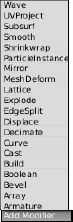
Because of space constraints, I can't give an extensive description on every modifier in the list, but I cover some of the most frequently used modifiers. That said, all of Blender's modifiers share some of the same controls between them. Have a gander at Figure 5-6. It shows the Modifier panel with two modifiers applied, Array and Bevel.
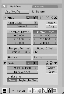
The first thing to notice is that the modifiers are stacked one below the other. This stacking is by design, and what's more, the order in which the modifiers appear in the stack is important. This is because one modifier feeds into the next one. So the second modifier, Bevel in this case, doesn't operate on the original mesh data. It actually operates on the "new" mesh data provided by the first modifier, Array, in this example.
Warning
The stacking order for modifiers is a little bit counter-intuitive if you think about it in terms of layers, where one builds on top of another. Blender's modifier stack does not work like that. Instead, it would be better to think of Blender's modifier stack as a snowball rolling down a hill. Each modifier you hit on the way down the hill adds something or changes something about your snowball, modifying it more and more as it comes to the base of the hill. The top-most modifier is the first modifier and operates on the original mesh data. The modifier immediately below it works on the data that comes from the first modifier, and so on down the line.
In the previous example, the object is first made into an array. Then, the mesh that is created by the Array modifier has its edges beveled so that they're not as sharp-cornered. Now, you can change the stacking order by using the up/down arrow buttons on the right side of each modifier block. Left-clicking the up-arrow raises a modifier in the stack (bringing it closer to being first), whereas the down-arrow lowers it. Left-click the X to the right of these buttons to remove the modifier altogether. The downward triangle that's to the left of each modifier's name collapses and expands that modifier block when you left-click it. This is useful for hiding a modifier's controls after you've decided upon the settings you want to use.
To the right of the names of each modifier are three buttons. From left to right, these buttons control whether the modifier is enabled for rendering, viewing in Object mode, and viewing in Edit mode. You may be wondering why you would ever want to disable a modifier after you've added it to the stack, rather than just removing it and adding it back in later. The main reason for this is that many of the modifiers have an extensive set of options available to them. You may want to see how your object renders with and without the modifier to decide whether you want to use it. You may want to edit your original mesh without seeing any of the changes made by the modifier. If you have a slow computer, you want to have the modifier enabled only when rendering so you can still work effectively without your computer choking on all the data coming from Blender. Those buttons next to each name are for situations like these.
Some modifiers, like Array, have an additional little circle-shaped button in the space after the enable/disable buttons. It's not labeled with an icon or anything, but its tooltip says Apply Modifier to Editing Cage During Edit Mode. This means that not only are the effects of the modifier visible in Edit mode, but you can also select and perform limited changes to the geometry created by the modifier.
Only two more buttons are common among all modifiers. They are the Apply and Copy buttons on the right side of each modifier block in the stack. Left-clicking the Apply button takes the changes made by the modifier and directly applies them to the original object. Doing this actually creates the additional vertices and edges in the original mesh to make it match the results done by the modifier, and then removes the modifier from the stack. I said before that modifiers were non-destructive, meaning that they don't permanently change the original object, but the Apply button is the one exception.
Note
The Apply button only works if the modifier is the first (top) modifier in the stack.
The Copy button creates a duplicate version of the modifier and adds it to the stack in the same position as the modifier you're duplicating, essentially forcing the original one further down the stack. You probably won't be using this function very often, but it's really useful when you need to double up a modifier, like if you want to bevel twice to get a more rounded edge than a single bevel operation can get you.
When I was first learning how to draw the human face, I used to have all sorts of problems because I'd draw half the face and then realize that I still needed to do just about the exact same thing all over again on the other side of the face. I found it tedious and difficult to try and match the first half of my drawing. Without fail, the first couple of hundred times I did it, something would always be off. An eye would be too large, an ear would be too high, and so on. I'm embarrassed to say that it actually took me quite a long time to get drawings that didn't look like Sloth from The Goonies. (Some of my co-workers might argue that some of my drawings still look that way!)
Fortunately, as a 3D computer artist, you don't have to go through all that. You can have the computer do the work for you. In Blender, you do this with the Mirror modifier (F9

The Mirror modifier basically makes a copy of all the mesh data in your object and flips it along its local X, Y, or Z axis, or any combination of those axes. The Mirror modifier also has the cool feature of merging vertices along the center seam of the object, so it looks like one unified piece. You can adjust how close vertices have to be to this seam in order to be merged by changing the Merge Limit value.
The X, Y, and Z buttons dictate which axis or axes your object is mirrored across. For most situations, the default setting of just the local X axis is all you really need. I nearly always enable the Do Clipping button. This button takes the vertices that have been merged — as dictated by the Merge Limit value — and locks them to the mirror axis. This is a great feature when you're working on vehicles or characters where you don't want to accidentally tear a hole along the center of your model while you're tweaking its shape with the Proportional Edit Tool (tab to Edit mode
The next large button is Mirror Vgroups. Vgroups stands for vertex groups. Vertices in a mesh can be assigned to arbitrary groups that you can designate in the Link and Materials panel of the Editing buttons, as shown in Figure 5-8.

The actual process of creating vertex groups and assigning individual vertices to a group is covered more in-depth in Chapter 11. However, the most basic way to create a vertex group is to press the New button under Vertex Groups in the Link and Materials panel while in Edit mode. This makes a new vertex group named Group. Now select some vertices in your mesh and press the Assign button back in the Link and Materials panel. Congratulations! You've created a vertex group.
Now, the effect of the Mirror Vgroups button doesn't make itself apparent until you apply the Mirror modifier. Here's how it works: Say you've selected some vertices and assigned them to a group named Group.R, indicating that it's the group for some vertices on the right-hand side. Say you've also created another group called Group.L for the corresponding vertices on the left-hand side, but because you have not yet applied the Mirror modifier, there's no way to assign vertices to this group. Well, if you have the Mirror Vgroups button activated when you apply the Mirror modifier, the newly created real vertices on the left side that correspond with the Group.R vertices are automatically assigned to Group.L. This effect propagates to other modifiers which are based on vertex group names, such as Armatures.
Referring back to Figure 5-7, the Mirror U and Mirror V buttons on the Mirror modifier do the same kind of thing that the Mirror Vgroups button does, but they refer to texture coordinates, or UV coordinates. (There's more on UV coordinates in Chapter 8.) The simplest explanation, though, is that UV coordinates allow you to take a flat image and map it to a three-dimensional surface. Enabling these buttons on the modifier mirrors the texture coordinates in the UV Image Editor and can possibly cut your texture unwrapping time in half. Also, unlike the Mirror Vgroups button, you don't have to apply the modifier to take advantage of the Mirror U or Mirror V features. To see the results of what these buttons do, when you have a texture loaded and your model unwrapped, bring up the View Properties floating window in the UV Image Editor (View
The last option in the Mirror modifier is the text field at the bottom that says Ob. By default, the Mirror modifier uses the object's center point as the basis for what to mirror. However, by typing in the name of any other object in this field, you can use that object's center as the point to mirror. With this, you can use an Empty as a kind of dynamic center point. That allows you to do fun things like animate a cartoon character splitting in half to get around an obstacle (literally!) and joining back together on the other side.
Another commonly used modifier, especially for organic models, is Subsurf. Subsurf is short for subdivision surfaces. If you have a background in another 3D modeling program, you might know them as sub-ds or subdivs. If you're not familiar with subdivision surfaces, the concept goes something like this: Blender takes the faces on a given mesh and subdivides them with a number of cuts that you arbitrarily decide upon (usually one to three cuts, or levels of subdivision). Now, when the faces are subdivided, Blender moves the edges of these faces closer together, trying to get a smooth transition from one face to the next. The end effect is that a cube with a Subsurf modifier begins looking more and more like a ball with each additional level of subdivision, as shown in Figure 5-9.

Now, the really cool thing about subdivision surfaces is that because they're implemented as a modifier, you get the smooth benefit of additional geometry without the headache of actually having to edit all of those extra vertices. In the preceding cube example, even at a subdivision level of six, if you Tab into edit mode, you control that form with just the eight vertices that make up the original cube. This is a very powerful way of working and nearly all high-end 3D animations use subdivision surfaces for just this reason. You have the smooth organic curves of dense geometry with the much more manageable control of a less dense, or low poly mesh, referred to as a cage.
For a better idea of the kind of results you can get with the Subsurf modifier, I'm going to break out Suzanne and apply it to her with the following steps:
Add a Monkey mesh (spacebar

Ooh! Ooh! Ooh!
Set smooth rendering on the monkey (F9
At this point, Suzanne is pretty standard. She looks smoother than the faceted look she had when first added, but she's still blocky looking.
Add a Subsurf modifier to the monkey (F9
Now that's Suzanne! Instantly, she looks a lot more natural and organic, even despite her inherently cartoony proportions. Feel free to increase the Levels number in the Subsurf modifier to see how much smoother Suzanne can be.
Tab into Edit mode and notice that the original mesh serves as the control cage for the subdivided mesh.
Editing the cage with Grab (G), Rotate (R), Scale (S), and Extrude (E) directly influences the appearance of the modified mesh within the cage.
Figure 5-10 shows the results of each of these steps.

As powerful as the Subsurf modifier is, only a limited number of options come with it in the modifier stack. Figure 5-11 shows the Subsurf modifier block as it appears in the Modifiers panel. The first option is a drop-down menu that gives you the choice between Catmull-Clark subdivision or Simple subdivision. The former is the default and behaves just like I've described previously. The latter works more like doing W
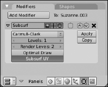
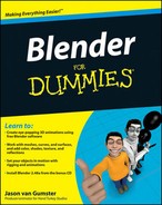
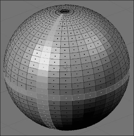
The next button down is the Levels option, which allows you to set the level of subdivision that you see on your model in the 3D View. It can be set to a whole number from 1 to 6. Because I like to keep my 3D view fast and responsive, I tend to keep this down at 1. Occasionally, I push it up to 2 or 3 to get a quick idea of what it might look like in the final output, but I always bring it back down to 1. Beneath the Levels option is a similar button for Render Levels. When you create the final output of your scene or animation, Blender uses this level of subdivision for your model, regardless of which level you set for the 3D view. It has the same range that Levels does, but typically this is set to a higher value because you usually want smoother, higher-quality models in your final render. Don't go too crazy with setting this value. On most of my work, which can get pretty detailed, I rarely ever use a setting higher than 3.
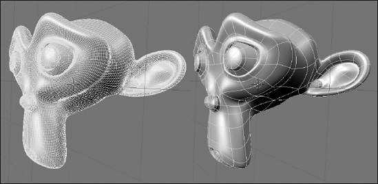
The Optimal Draw button is something I typically like to leave turned on all the time. It hides the extra edges that are created by the modifier when you view the model in wireframe view. On a complex scene, hiding the edges can definitely help you make sense of things when working in wireframe. Figure 5-12 shows the difference Optimal Draw makes on a Suzanne model with three levels of subdivision.
Tip
When working with the Subsurf modifier, I typically like to have this option on, along with the Apply Modifier to Cage button, otherwise known as "that circle-shaped button next to the modifier name." Everyone's different, though, so play with it on your own and see what works best for you.
Use the Subsurf UV button for texturing. Like the Mirror U and Mirror V buttons in the Mirror modifier, enabling this button adds the additional geometry to your UV map without requiring you to apply the modifier. Again, this can be quite a helpful timesaver when you're setting up your model for texturing. Also like the Mirror U and Mirror V options, you can see the results of the Subsurf UV button by enabling the Final Shadow button in the UV Image Editor (Shift+F10
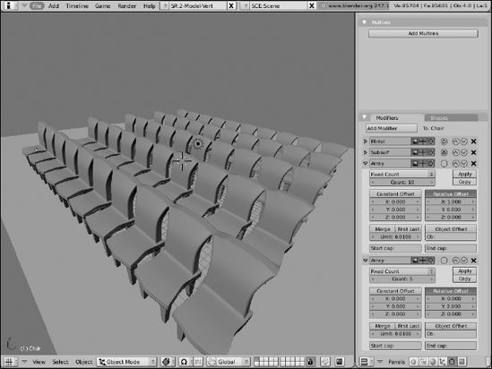
One of the coolest and most-fun-to-play-with modifiers in Blender is the Array modifier. In its simplest application, this modifier duplicates the mesh a specified number of times and places those duplicates in line evenly spaced apart. Have a model of a chair and need to put lines of chairs in a room to make it look like a meeting hall? Using a couple of Array modifiers together is a great way to do just that! Figure 5-13 is a screenshot of Blender being used to create that sort of scene.
Tip
You're not limited to using just one Array modifier on your object. The effect in Figure 5-13 was achieved by using two Array modifiers stacked together, one for the first row of chairs going across the room and the second to create multiple copies of that first row. Using multiple arrays in a row is an excellent way to build a complex scene with just one object.
Blender's Array modifier is loaded with all kinds of cool functions that can be used in lots of interesting ways. Some ways facilitate our desire to be lazy by making the computer do as much of the repetitive, tedious tasks for us as possible. (For example, it can be used to model a staircase or a chain-link fence or a wall of bricks.) However, you could also use it to do some really incredible abstract animations or specialized tentacles or even rows of dancing robots!
The bulk of the power in the Array modifier lies in how it handles offsets, or the distances apart that the duplicates are set relative to one another. As shown in Figure 5-14, the Array modifier offers three different sorts of offsets, all of which can be used at the same time.
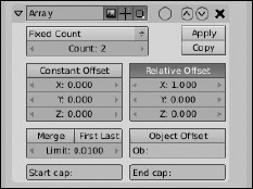
Constant Offset: This offset adds a fixed distance to each duplicated object in the array, in Blender units. So setting the X value beneath this button to −5.0 shifts each of the duplicates five units in the negative X direction. The same behavior happens in the Y and Z axes when you set the values for those offsets as well.
Relative Offset: Think of the Relative Offset like a multiplication factor, based on the width, height, and depth of the object. So no matter how large or small the object is, if you set the Z value to 1.0, for example, each duplicated object in the array is stacked directly on top of the one below it. This type of offset is the one that's used by default when you first add the Array modifier.
Object Offset: The Object Offset is my personal favorite offset because of its incredible versatility. It takes the position of any object you name in the Ob: field — I prefer to use Empties for this — and uses its relative distance from the mesh you've added to Array as the offset. But that's just the start of it! Using this offset also takes into account the rotation and scale of the object you enter. So if you have an Empty that's one Blender unit away from your object, scaled to twice its original size and rotated 15 degrees on the Y axis, each subsequent duplicate is scaled twice as large as the previous and rotated an additional 15 degrees. Now you can make a spiral staircase like the one in Figure 5-15. And if you felt inclined to create a staircase where the stairs can be collapsed into each other and hidden, it's a simple as animating the offset object!
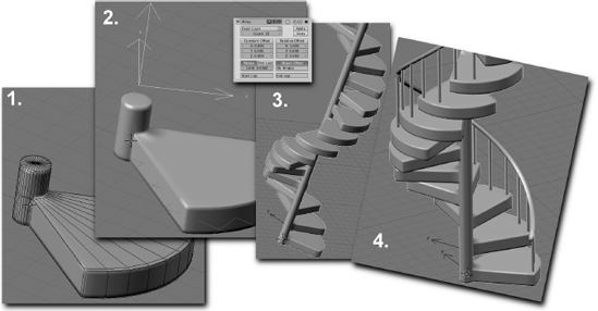
Figure 5-15. 1) Model the step. 2) Add an Empty for Object Offset and rotate in Z. 3) Add the Array modifier. 4) Make it pretty.
You also have a lot of control over how many duplicates the Array modifier creates. This is controlled with the Length Fit drop-down menu at the top of the Array modifier block. By default, the Length Fit setting is Fixed Count and you explicitly enter the number of duplicates in the Count field below it. That isn't your only option, however. You actually have three:
Fixed Count: As described above, this lets you explicitly enter the exact number of duplicates you would like to create, up to 1000.
Fixed Length: This creates the proper count of duplicate objects to fit in the distance that you define. Bear in mind that this length is not exactly in Blender units. It uses the local coordinate system of the object that you're making an array of, so the length you choose is multiplied by the scale of that original object as shown in the Transform Properties floating window (N).
Fit to Curve Length: If you choose this option, you can enter the name of a curve object in the Ob field below it. When you do this, Blender calculates the length of that curve and uses that as the length to fill in with duplicated objects. Using this option together with a Curve modifier is a nice quick-n-dirty way of creating a linked metal chain like the one shown in Figure 5-16.
Another cool feature in the Array modifier is the ability to merge the vertices in one duplicate that are near the vertices in another. With the Merge button enabled and some fine adjustment to the Limit value, you can make your model look like a single unified piece, rather than being composed of individual duplicates. I've used this feature to model rope, train tracks, and stair rails, for example. The First Last button toggles to determine if the vertices in the last duplicated instance are allowed to merge with the nearby vertices in the first object of the array. Use this with Object Offset and you can create a closed loop out of your duplicates, all merged together.

Figure 5-16. Creating a chain using the Fit Length to Curve option in the Array modifier along with a Curve modifier.
Say you're using the Array modifier to create a handrail for your spiral staircase and you don't want the handrail to simply stop at the beginning and end. Instead, you'd like the end of the handrail to have ornamental caps. You could model something and try to place it by hand, but this could get problematic if you have to make changes or animate the handrail in the future. (Hey, this is computer graphics. Handrails that move and are animated make complete sense!) So another way to handle this is to use the Start cap and End cap fields in the Array modifier. After you've modeled what you want the cap to look like, you can type the name of that object in these fields and it will be placed at the beginning and the end of the array, respectively. Pretty slick, huh?
Over the years, as computers have gotten more powerful and more capable of handling dense high poly models with millions of vertices, computer graphics artists have wanted more and more control over the vertices in their meshes. Using a Subsurf modifier is great for adding geometry to make models look more organic, but what if you're modeling a monster and you want to model a scar in his face? You have to apply the modifier to have access and control over those additional vertices. And even though the computer may be able to handle having them there, a million vertices is a lot for you to try to control and keep track of, even with all of the various selection methods and the Proportional Edit tool. This is exactly why Blender has multi-resolution meshes and Sculpt mode.
Multi-resolution, or multires for short, meshes address the problem of having to apply the Subsurf modifier before you can directly control the vertices that it creates. With a multires mesh, you can freely move between a level 1 subdivision and a level 6 subdivision, just like with the Subsurf modifier. However, the difference is that you can directly control the vertices of the level 6 subdivision just as easily as the level 1 subdivision using Blender's Sculpt mode. And changes made at either level can be seen at the other one. (To varying levels of detail, depending on the level you're looking at. If you make a very fine detail change in level 6, it may not be readily apparent at level 1.) Figure 5-17 shows what the Multires panel looks like before and after you add Multires to your model.
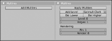
Figure 5-17. The Multires panel in the Editing buttons before (left) and after (right), adding Multires and a couple levels of subdivision.
Turning a mesh into a multires mesh is as simple as left-clicking the Add Multires button in the Multires panel and then left-clicking the Add Level button for each level of subdivision that you would like to add to your mesh. Unlike with the Subsurf modifier, you don't have exactly six levels of subdivision to switch between. In Multires, the number can be as low as zero and as high as your computer's processor and memory can handle. And before adding a level, you have the option of choosing Catmull-Clark Subdivision or Simple Subdivision, like you can with the Subsurf modifier. The only difference here is that you cannot freely change between subdivision types on a given level with Multires. After you left-click the Add Level button, your choice is made.
Tip
If you have a Subsurf modifier on your mesh, I recommend applying it to your mesh or removing it from the modifier stack before adding Multires. Because Multires uses the same process to create subdivision levels, you don't need to have both active at the same time.
After you have a level added, you have some additional options available. The first two buttons that appear are Del Lower and Del Higher. Clicking these buttons removes all subdivision levels less than or greater than the level you are currently in, respectively. So if you have five levels of subdivision and you're at level 4, clicking Del Lower effectively kills levels 1 through 3. When these levels are removed, the current level — in this example, level 4 — becomes the new level 1. Del Higher works in a similar fashion.
The next field down, Level, lets you set which subdivision level you're currently looking at from the levels that you've added to your mesh. Below that is the Edges field. The Edges field allows you to set which level's edges you would like Blender to show in the 3D view. Setting it to 1 gives you an effect that's similar to Optimal Draw on the Subsurf modifier. Higher values progressively show more and more edges. Some 3D modelers who use sculpting tools like to overlay the model's wireframe on the mesh (F7
In the bottom right of this area are two fields associated with rendering. The Pin value determines which level of subdivision you want the modifier stack to work on when you render. By default, this is set to level 1. Increasing this value means that more vertices get seen by the modifier stack and can therefore substantially increase your render time, so do so carefully — or at least with the knowledge that you may have time to go out for a long meal and a nap while Blender renders your model. The Render value tells Blender which subdivision level you would like to have rendered. By default, this is set to your highest level. If you're rendering a test preview, you can speed things up by reducing this value.
Warning
Currently, multires meshes are created and managed in the Multires panel of the Editing buttons (F9). In future versions of Blender, the plan is to make Multires work like any other modifier, so some features may vary slightly if you're using a version of Blender newer than version 2.47.
Now, if you try to tab into Edit mode on a multires mesh, you may be faced with so many vertices that it's not easy or even useful to select and edit just one vertex or a few of them. Sculpt mode helps you manage all of these additional vertices created by Multires. It treats your mesh very much like a solid piece of clay. You have a variety of "sculpt brushes" that help you shape and form your mesh to look exactly how you want. Activate Sculpt mode from the Mode menu in the header of the 3D view, as shown in Figure 5-18. When you're in Sculpt mode, three additional tabs show up in the Editing buttons along with the Multires panel: Sculpt, Brush, and Texture.

Tip
If you have a drawing tablet like the ones manufactured by Wacom, Sculpt mode takes advantage of the pressure sensitivity that a tablet offers. You can adjust the sensitivity and size of the tablet by going to Sculpt
Figure 5-19 shows the contents of the Sculpt panel. This is the primary panel for working in Sculpt mode. In fact, if you have the Transform Properties floating window (N) up in 3D view, when you switch to Sculpt mode, its content changes to match what's in this panel so you have quick access to it within the 3D view. The buttons in this panel can be broken down into three sections: brush types, brush controls, and axis-related controls.
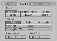
Sculpt mode offers you seven different types of brushes to work with, each one modifying your mesh in a very specific way. All brushes work by left-clicking with the brush cursor over the mesh and dragging the cursor around the 3D View. If you're using a drawing tablet, this is a very natural way to work. Below are brief descriptions of each sculpt brush:
Draw (D): The Draw brush basically pulls the surface of your mesh outward (or inward, if you enable the Sub button). By default, the brush works with an even fall-off, so the raised areas you draw tend to flow smoothly back into the rest of the mesh.
Smooth (S): If you have jagged parts of your mesh or there are undesirable surface irregularities created while sculpting, using the Smooth brush cleans up those bumpy parts and makes the surface of your mesh, well, smoother.
Pinch (P): If you enable the Pinch brush, vertices are pulled toward the center of your brush cursor as you move it over the mesh. This is a great way to add ridges and creases to a model.
Inflate (I): The Inflate brush works a lot like the Draw brush. However, rather than move vertices more or less uniformly from the meshes surface, when you run the Inflate brush over your mesh, vertices move along their own local normals. This brush is good for fattening parts of a model.
Grab (G): When you left-click and drag your mouse cursor on a mesh with the Grab brush activated, the vertices that are within the brush cursor's circle are moved to wherever you drag your mouse to. This is like selecting a bunch of vertices in Edit mode and pressing G.
Layer (L): The Layer brush is like the Draw brush with a maximum height that it pulls the vertices, basically creating a raised mesa on the surface of your mesh.
Flatten (T): In some ways, this brush does the opposite of the Draw brush. Where the Draw brush pulls vertices away from the surface of a mesh, the Flatten brush lowers vertices to try and get them to be as flat or planar as possible. If you're sculpting a landscape and you decide to remove a hill, this is the brush you want to use.
The next section of buttons, under the heading of Shape, actually control how the sculpt brushes influence your mesh. The first two buttons, Add and Sub, are only available for the Draw, Pinch, Inflate, and Layer buttons. Add is the default behavior described previously. If you enable Sub, it does the inverse. For instance, with Sub enabled, the Pinch brush pushes vertices away from the center of the brush cursor instead of pulling them in. Also, note that regardless of whether you've enabled Add or Sub, pressing Shift while using the brush does the opposite behavior. For example, if you're using the Draw brush with Add enabled, the normal behavior creates a small hill wherever you move your mouse cursor. If you press Shift+left-click and drag, you sculpt a small valley instead. Alternatively, you can toggle between Add and Sub by pressing V.
By default, if you left-click and hold your left mouse button down without moving the mouse, the Sculpt tool doesn't do a whole lot. It performs the brush's operation once and then waits for you to move your mouse. Suppose you prefer that the brush keep operating for as long as you hold down the left mouse button, regardless of whether you actually move the mouse. Enabling the Airbrush button (A) gives you just that ability. So if part of your mesh is an incredibly jaggy mess, you can switch to the Smooth brush (S), enable Airbrush (A), left-click on the jagged area, and hold down that left mouse button until the jaggies are gone.
The Size and Strength sliders control the size and strength of the brush you're currently using. There are hotkeys for changing these values while in the 3D view so you don't have to bring up this panel. To change brush size, press F, move your mouse until the brush cursor is the desired size, and left-click to confirm. To adjust the brush strength, press Shift+F and move your mouse to the center of the circle that pops up to increase the strength or away from the center to decrease the strength. When you're at the strength you want, left-click to confirm.
The next two blocks of buttons control how the sculpt brushes modify your mesh relative to the object's local axes. For example, if you left-click the X button under Symmetry, anything you do on the left side of the mesh automatically also happens on the right side of the mesh. This is an excellent timesaver for doing involved tasks like sculpting faces.
Likewise, the X, Y, and Z buttons under the LockAxis label constrain a vertex's movement in that axis. For instance, if you decide that you only want the Draw brush to move vertices in the Z direction, you would left-click the X and Y buttons under LockAxis to keep vertices under your brush cursor from moving in those directions.
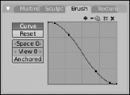
The Brush panel gives you control over how your sculpting brushes behave. By default, a curve controls how the intensity of the brush rolls off to the edges of the brush cursor. You can disable this control in favor of a more linear fall-off by left-clicking the Curve button, or you can edit the curve in the graph to the right to have more customized intensity fall-off. Figure 5-20 shows the contents of the Brush panel.
In the Texture panel, you have a set of eight texture channels, in addition to the Default, that you can use as brushes. So any texture that you can load or create in the Texture buttons (F6) can be used as a brush when you sculpt. This is an excellent way to get more details added to your mesh while sculpting. One button that you may want to use when you've loaded a texture into this panel is the Rake button. When this button is enabled, the texture is rotated as you sculpt to match the motion of the brush. This helps you avoid creating unnatural patterns from your textures when you sculpt. Figure 5-21 shows the contents of the Texture panel.

Tip
Sculpting with a high level of subdivisions can be taxing on your computer, using a lot of memory to store all of those additional vertices. If you use too many levels of subdivision, your computer may run out of memory and Blender could lock up or crash. In an effort to prevent this and give themselves more vertices to play with, many 3D modelers who use Blender's Multires go to the User Preferences under Edit Methods to disable Global Undo and turn down the number of Undo Steps from the default value of 32 down to 0. This removes the safety net of undo, but it can often improve Blender's performance while sculpting.
Table 5-1 gives you a quick reference for the hotkeys used in Sculpt mode.
Table 5-1. Hotkeys for Sculpt Mode
Description | Hotkey | Menu Access |
|---|---|---|
Draw Brush | D | Sculpt |
Smooth Brush | S | Sculpt |
Pinch Brush | P | Sculpt |
Inflate Brush | I | Sculpt |
Grab Brush | G | Sculpt |
Layer Brush | L | Sculpt |
Flatten Brush | T | Sculpt |
Toggle Add/Sub | V or Shift+left-click | Sculpt |
Airbrush | A | Sculpt |
X Symmetry | X | Sculpt |
Y Symmetry | Y | Sculpt |
Z Symmetry | Z | Sculpt |
Rotate Brush | Ctrl+F | Sculpt |
Brush Strength | Shift+F | Sculpt |
Brush Size | F | Sculpt |
Hide mesh outside of selection box | Shift+Ctrl+left-click | N/A |
Hide mesh within selection box | Shift+Ctrl+right-click | N/A |
Unhide All | Alt+H | N/A |
Increase multires level | Page Up | N/A |
Decrease multires level | Page Down | N/A |