This chapter serves as a good pairing with Chapter 7. In that chapter, I wrote about adjusting the materials on your objects, but that was in broad strokes. That chapter covered how light reacts with the surface of your material so you could deal with the object's color, how that color spreads across the surface of the object, and how the specular highlights on that object behave. Of course, these are all broad strokes. If you want a more controlled way of adjusting the look of your object, then using material settings alone won't get you there. You could use Vertex paint, but if you're working on a model that you intend to animate, this causes you to have many extraneous vertices just for color. Those vertices end up slowing down the processes of rigging, animating, and even rendering. Also, you may want to have material changes that are independent of the edge flow and topology of your mesh.
For those sorts of scenarios, you're going to want to use textures. Generally speaking, a texture is a kind of image that you stretch or tile over the surface of your object to give it more detail without adding more vertices. Not only can textures influence the color of your object, but they can allow you to make additional adjustments, such as stipulating the specularity of some specific parts of the model. For instance, on a human face skin tends to be shinier across the nose and forehead, and a reduced specularity exists around the eyes. With textures, you can control these sorts of things. And the purpose of this chapter is to show you how you can apply that control.
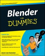
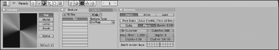
You can add and edit textures to a material using the Texture buttons (F6), as shown in Figure 8-1.
Like the Material buttons, the Texture buttons have a Preview panel that displays the texture as you work on it. By default, the display in the Preview panel is completely black because the initial texture type is None. You can change this in the Texture panel with the drop-down list button on the right side of the panel. The left side of the panel is similar to the Texture panel in the Material buttons, and for good reason. These are the same ten texture channels that your material has available. The difference, though, is that with the Texture buttons, you can actually control what goes into these channels. Left-click any channel button to choose the channel that you want to work on. The channels that have textures in them display the name of the texture in the channel button. You can customize the name of the texture by left-clicking the name field at the top of the panel. This name field is part of a set of datablock control buttons that work just like the ones used in the Links and Pipeline panel of the Material buttons or the Object and Links panel of the Object buttons. As a quick refresher, here's what each button in the block does:
The up/down button on the left gives you the ability to add a new texture or load an existing one.
The X button disconnects the texture datablock from the channel.
The button with the automobile icon automatically creates a texture name based on the texture type.
The F button creates a fake user for the texture datablock so that datablock won't be deleted even though it may have no links to any material's texture channels.
You can use basically two kinds of textures in Blender: image-based textures and procedural textures. Unlike image-based textures, where you explicitly create and load an image as a texture, procedural textures are created in software with a specific pattern algorithm. The advantage of procedural textures is that you can quickly add a level of detail to your objects without worrying about cleaning up seams from tiling errors or unwrapping the mesh. The software handles all of this for you. Of course, procedurals can be a bit more difficult to control than image-based textures. For instance, if you have a character with dark circles under his eyes, getting those circles to only show up where you want can be pretty tough, maybe even impossible. So the ideal use for procedural textures is as broad strokes where you don't need fine placement control. They're great for creating a foundation or a base to start with, such as providing the rough texture an orange rind's surface.
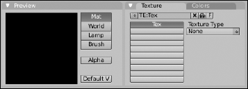
Blender has 11 procedural texture types that you can work with, accessible through the Texture Type drop-down list menu in the Texture panel of the Texture buttons (F6). In addition to these procedurals, you can also choose PlugIn, Image, or None as textures. All of the available texture types are shown in Figure 8-2.
With only a couple of exceptions, when you select a texture type that you wish to use, a third panel appears in the Texture buttons. The options from one texture type to another vary, but with the exception of Voronoi, Noise, Blend, and EnvMap, all of the procedural textures share an option called Noise Basis. The Noise Basis is a specific type of pseudorandom pattern that influences the appearance of a procedural texture. There are two controls for the Noise Basis option that are always located at the bottom of the newly created panel: a Noise Basis drop-down menu and a Nabla value. The Nabla value offer some more advanced control of the sharpness or smoothness of the texture when it's applied to the material, but the Noise Basis offers an immense amount of flexibility in controlling a procedural texture's appearance. Left-clicking this drop-down menu list box displays the options shown in Figure 8-3.

The types of Noise Basis can be roughly broken down into three different kinds of noise:
CellNoise: A blocky, pixelated type of noise.
Voronoi family: These noise types, including Crackle, F2-F1, F4, F3, F2, and F1 are all roughly based on the same algorithm. One of the primary attributes of Voronoi noise is a somewhat distinct partitioning throughout the texture with generally straight lines. This is most apparent in the Voronoi Crackle noise basis. These noise types are good for hammered metal, scales, veins, and that dry desert floor look.
Cloudy noise: Cloudy is my own terminology, but it includes the Improved Perlin, Original Perlin, and Blender Original Noise Basis types. These types of noise tend to have more organic feel to them and work well for generic bump textures and clouds or mist.
The next few sections go into rough detail on each type of procedural texture.
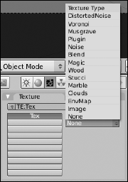
The Distorted Noise texture is pretty slick. Actually, strike that; this type of texture is best suited to very rough, complex surfaces. The way it works is pretty cool, though. You use one procedural noise texture, specified by the Distortion Noise menu, to distort and influence the texture of your noise basis. With this, you can get some really unique textures. Figure 8-4 shows the Texture buttons for controlling a Distorted Noise texture.
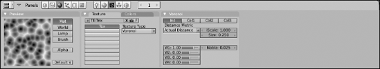
The Voronoi procedural texture does not have a Noise Basis. This is because it's a more detailed control over the same algorithm that is used for the Voronoi Noise Basis options. It may be helpful to think of those basis options as presets, whereas this texture gives you full control over what you can do with the Voronoi texture. It's a pretty versatile texture, too. You can use it to create scales, veins, stained glass, textured metals, or colorful mosaics. Figure 8-5 shows the Voronoi Texture buttons.
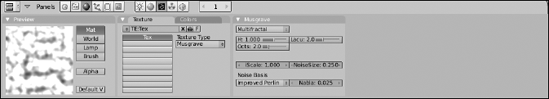
This procedural texture is extremely flexible and very well suited for organic materials. You can use it for rock cracks, generic noise, clouds, and even as a mask for rust patterns. As a matter of fact, with enough tweaking, you could probably get a Musgrave texture to look like nearly any other procedural texture. Of course, the trade-off is that it takes a bit longer to render than most of the other textures. Figure 8-6 shows the Texture buttons for controlling a Musgrave texture.
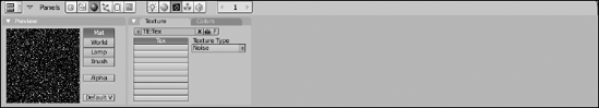
This is the simplest procedural texture in Blender (well, the None texture type is probably simpler, but it's not very useful). This texture has no controls: It's simply raw noise. That means that you'll never get the same results twice using this texture. Each time you render, the noise pattern is different. This might be annoying if you're looking to do a bump map. However, if you're looking to have "white noise" on a TV screen, this texture is perfect. As Figure 8-7 shows, the Noise texture has absolutely no controls.
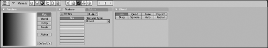
The Blend texture is one of the unsung heroes in Blender's procedural texture arsenals. It may seem like a simple gradient, but with the right mapping, it's really quite versatile. I've used Blend textures for mixing two other textures together, creating simple toon-like outlines for meshes, and for adjusting the color along the length of hair strands. The real power of the Blend texture can be seen when you use it with a colorband that you define in the Colors panel of the Texture buttons. Figure 8-8 shows the Texture buttons for controlling a Blend texture.
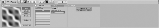
At first glance, the Magic texture may seem to be completely useless — or at the very least, too weird to be useful. However, I've managed to find quite a few cool uses for this eccentric little texture. If you treat it as a bump map, it works well for creating a knit texture for blankets and other types of cloth. If you stretch the texture with your mapping settings, you can use it to recreate the thin filmy look that occurs when oil mixes with water. And, of course, you can use it to make a wacky wild-colored shirt. Figure 8-9 shows the controls for the Magic texture.
The Wood texture is a bit of a misnomer. Sure, you can use it to create textures that are pretty close to what you see on cut planks of wood. However, it's a lot more versatile than that. You can use the wood texture to create nearly any sort of striped texture. I've actually even used it to fake the look of mini-blinds in a window. Figure 8-10 shows the Wood Texture button controls.

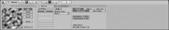
Stucci is a nice organic texture that's most useful for creating bump maps. It's great for industrial and architectural materials like stucco, concrete, and asphalt. It's also handy if you just want to give your object's surface a little variety and roughen it up a bit. In Figure 8-11 are the buttons for controlling the options of the Stucci texture.
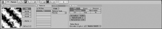
This texture has a lot of similarities with the Wood texture; however, as Figure 8-12 shows, it's a lot more turbulent. You can use it for creating the look of polished marble, but the turbulent nature of the texture also lends itself nicely to be used as a fire texture and, to a lesser extent, the small ripples you get in ponds, lakes, and smaller pools of water.
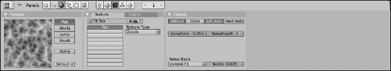
The Clouds texture is a good general purpose texture. You can treat it as a go-to texture for general bumps, smoke, and clouds. Figure 8-13 shows the Texture buttons for controlling a Clouds texture.
EnvMap is short for environment map. It's a way of using a texture to fake reflections on your object. It works by taking the position of a given object and rendering an image in six directions around that object: up, down, left, right, forward, and back. These images are then mapped to the surface of your object. So, this isn't exactly a procedural texture in the traditional sense, but because the environment images are taken automatically, I'll say it's part procedural and part image-based.
Environment maps aren't as accurate as using raytraced reflection, but they can be quite a bit faster. So if you need a generically reflective surface that doesn't need to be accurate, environment maps are a handy tool that keep your render times short. One thing to note about the EnvMap panel, as shown in Figure 8-14, is the Ob field. By default, this field is set to be the object that you intend on mapping the texture to. However, sometimes you can get a better reflective effect by using the location of a different object, such as an empty. This is particularly true when applying an environment map to an irregular surface.
Note
When using environment maps, make sure you do two things. First, enable the Refl button in the Map To panel of the Material buttons (F5). Secondly, enable the EnvMap button in the Render panel of the Render buttons (F10). Unless you do both of these things, your environment map won't work properly.
After you've created your texture, be it procedural or image-based, you're going to have to relate that texture to your material and, by extension, the surface of your object. This is done with a process called mapping, which basically consists of relating a location on a texture to a location on the surface of an object. Mapping controls are located in the panels of the last block of the Material buttons (F5). Specifically, I'm referring to the Map Input and Map To panels, as shown in Figure 8-15.
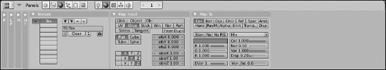
The Map Input panel controls how the texture is mapped to the object, defining how the texture coordinates are projected on it. The most important buttons are the block of mapping options at the top of this panel. The following list explains the type of mapping that each button represents:
Glob (Global coordinates): Choosing this option uses the scene's coordinates to define the texture space. So if you have an animated object with a texture mapped this way, the texture will seem to be locked in place as the object moves across it. It's a kind of strange effect, but it's a helpful effect in a few situations, such as faking shadows on a moving character.
Object: This is a neat option, allowing you to use a different object's location as a means of placing a texture on your object. To tell Blender which object you want to use for this, type its name in the Ob field. For example, you could load an image texture of a logo and place that logo on a model of a car by using the location, size, and orientation of an empty.
UV: UV coordinates are probably the most precise way of mapping a texture to an object. NURBS surfaces have UV coordinates by default. For meshes, however, getting UV coordinates requires you to go through a process called unwrapping. To understand this process, think about a globe and a map of the world. The map of the world uses the latitude and longitude lines to relate a point on the three-dimensional surface of the globe to the two-dimensional surface of the map. In essence, the world map is an unwrapped texture on the globe, whereas the latitude and longitude lines are the UVs. More on unwrapping in the next section, "Unwrapping a Mesh."
Orco (Original coordinates): This is the default setting and should work fine for most situations, especially when you are using procedural coordinates.
Stick (Sticky or Camera coordinates): Sticky coordinates are a way of getting a somewhat precise mapping based on the location and orientation of the camera. You position your camera at some location, pointing toward your object. In the Editing buttons (F9), within the Mesh panel, left-click the Make button next to the word Sticky. This creates a mapping on the mesh based on the camera's current position. And now, unlike Global or Window coordinates, when you animate the object or the camera, the texture won't move. It stays stuck to the object.
Strand: This option is not visible by default. It only appears when your object has a particle system with the Strand render option enabled. When that happens, this button takes the place of the Stick button. As the name indicates, it's intended specifically for particle strands. When activated, the texture is mapped along the length of the strand.
Win (Window coordinates): This option is similar to the Global coordinates option, but rather than use the scene's global coordinates, it uses the coordinates from the finished render window. In other words, it uses the camera's coordinates. But unlike Sticky coordinates, which use the camera's coordinates just once, this option always uses them. So if the object is animated, the texture is not stuck to it. It remains in place.
Nor (Normal coordinates): Enabling this button causes the texture to be mapped according to the normal vectors along the surface of the object. This is helpful for effects that require textures to react to the viewing angle of the camera.
Refl (Reflection coordinates): The reflection option uses the direction of a reflection vector to map your texture to the object. Basically, you want to use this option with an environment map texture (EnvMap) to get fake reflections when you don't need the accuracy of raytracing.
Stress: Stress maps are a pretty cool option that's intended for use with dynamic or simulated geometry. The stress value is the difference between the location of an original texture coordinate and location of the coordinate when rendered. As an example, say you have a character with stretchy arms. You could use stress mapping as a mask to make the arms more translucent the more they stretch.
Tangent: In some ways, this option is similar to Normal coordinates. However, rather than use the surface normal, it uses an optional tangent vector to map the texture coordinates. Notice that I wrote "optional" tangent vector. By default, there is no tangent vector on the material, so enabling this button by itself won't do much to it. However, if you left-click the Tangent V button at the top right of the Shaders panel, you have a tangent vector for your texture to work with.
In addition to these map inputs, you can also control what's called the texture projection. This, along with the map input, controls how the texture is applied to the mesh for everything except UV textures. Because UV textures explicitly map a texture coordinate to a coordinate on the surface of your object, changing projection doesn't have an effect on anything. Blender has four different types of projection:
Flat: This type of projection is the easiest to visualize. Imagine you have your texture loaded in a slide projector. When you point it at a wall, you get the best results. However, if you point it at a curved or uneven surface, you get a little bit of distortion. This is basically what happens with Flat projection.
Cube: Cube projection uses the same idea as flat projection, but rather than having just one projector, imagine you have one pointing at the front, left, and top of your object (and shining through to the other side). The texture appears on all six sides of the cube. Of course, when you try to project on a more curved surface, you still get some seams and distortion.
Tube: Tube projection is where the slide projector metaphor kind of stops making sense. Imagine that you have the unique ability to project on a curved surface without the distortion. This, of course, is pretty close to impossible in the real world, but pretty trivial in computer graphics. Using Tube projection is ideal for putting labels on bottles or applying other sorts of textures to tubular objects.
Sphere: Spherical projection is best suited for spherical objects like planets and balls, and it's also the "cleanest" way to apply a texture to an arbitrary three-dimensional surface because it usually doesn't leave any noticeable seams as does Cube projection.
Figure 8-16 shows a set of primitive objects with Flat, Cube, Tube, and Sphere projection.

Along the right side of the Map Input panel are fields that give you finer control over how your texture is positioned on your object. The ofsX, ofsY, and ofsZ values define an offset in the X, Y, and Z directions, respectively. And the sizeX, sizeY, and sizeZ values scale the texture in each of those directions. The grid of Xs, Ys, and Zs at the bottom left of this panel allow you to reorder the axes of the texture, letting you flip it around to try and get the best fit.
Note
The offset and size values are not relative to the global or local coordinates in the 3D View. They're actually relative to the texture image itself. The X and Y values are horizontal and vertical whereas the Z value is a depth value into the texture. The Z values don't have a lot of influence unless the texture is a procedural texture with a Noise Basis.
Not only do you control how a texture is mapped to an object, but you also control how that texture affects the material. The controls for this are in the first two rows of buttons of the Map To panel.
Tip
Some of these Map To buttons are simple toggles. Left-clicking them once turns them on and left-clicking them a second time turns them off. However, most of them are three-state buttons. This means that the first left-click enables the option, but the second left-click changes the text in the button to yellow, indicating that the texture's effect on the material is inverted. A third left-click on the button disables it.
You can use any combination of the following options:
Col (Color — toggle): Affects the material's diffuse color.
Nor (Normal — three-state): Influences the direction of the surface normals on the material. Enabling this button enables bump mapping. It can give your object much more detail without the computational slowdown of additional geometry.
Csp (Specular Color — toggle): Affects the material's specular color.
Cmir (Mirror Color — toggle): Affects the material's mirror color.
Ref (Reflection — three-state): Influences the reflection value in the material's diffuse shader.
Spec (Specularity — three-state): Influences the specularity in the material's specular shader.
Amb (Ambience — three-state): Affects the amount of ambient light the material gets.
Hard (Specular Hardness — three-state): Affects the specular hardness values for the specular shaders that support it.
RayMir (Raytraced Reflection — three-state): Influences the amount of raytraced reflection that the material has.
Alpha (three-state): Controls the transparency and opacity of the material.
Emit (three-state): Affects the material's emit value for radiosity.
TransLu (Tranlucency — three-state): Affects the amount of translucency in the material.
Disp (Displacement – three-state): This option is similar to the Nor option, except that it actually moves the geometry of the object based on the texture map. Whereas bump mapping only makes it look like geometry is added and moved around by tricking out the surface normal, displacement actually moves it around. The downside to Blender's displacement is that you have to have the vertices already in place to move around. It won't create them for you on the fly. You can get around this a bit by using the Subsurf modifier, but creating your additional vertices with that definitely increases your render times.
In the previous section, I mentioned that the most precise type of mapping you can use is UV mapping. Not only is UV mapping precise, but it also allows you to take advantage of a couple of other features in Blender, such as Texture Paint mode and texture baking. With NURBS surfaces, you get UV coordinates "for free" as part of their structure. However, Blender is predominantly a mesh editor, and in order to get proper UV coordinates on your mesh objects, you must put them through a process known as unwrapping. You unwrap a mesh in Blender by selecting all vertices (A) and pressing U while in Edit mode (Tab). Of course, pressing U brings up a menu with a variety of options to choose from, as shown in Figure 8-17.
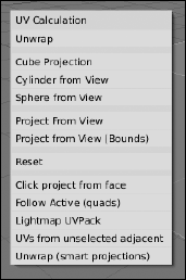
However, despite this variety of options, unless your mesh is simple or a special case, you should use the first menu item, Unwrap. Blender has very powerful unwrapping tools, but to take full advantage of them, you need to first define some seams. Remember that you're basically trying to flatten 3D surface to a 2D plane. In order to do so, you need to tell Blender where it can start pulling the mesh apart. This is a seam. If you were unwrapping a globe, you might choose the prime meridian as your seam. I like to think about it like a stuffed animal, such as a teddy bear. The seam is where the bear is stitched together from flat pieces of cloth. To add a seam to your mesh, use the following steps:
Tab into Edit mode and switch to Edge Select mode (Tab

You could also do this from Vertex Select mode, but I find that it's easier in Edge Select.
Select the series of edges you want to make into a seam (right-click
Using an edge loop selection (Alt+right-click) can really be helpful here. Everyone has their own tastes when it comes to defining seams, but a good rule of thumb is to put them on parts of the mesh that are easier to hide.
Use the Edge Specials menu to make the seam (Ctrl+E
Seams on your mesh are highlighted in orange. If you mistakenly make a seam with the wrong edges, you can remove the seam by selecting those edges (right-click) and pressing Ctrl+E
With your seams defined, you're ready to unwrap your mesh. In order to see what you're doing, though, there are a couple changes you should make to your screen layout. First, you should probably change the drawtype of your 3D View to Textured (Alt+Z). Then split off a new window and change it to be a UV/Image Editor window (Shift+F10). Your layout should look something like what is shown in Figure 8-18.

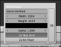
The next thing you need is an image to map to your mesh. It's common practice when unwrapping to use something called a test grid. This is basically an image with a colored checkerboard pattern. It's helpful for trying to figure out where the texture is stretched on your mesh. To add a test grid, go to the UV/Image Editor window and choose Image
Tip
It's possible to unwrap your mesh without going through the process of adding a test grid, but I find that it's helpful to have the grid up there so you have a frame of reference to work from when unwrapping.
Tip
Also, you should note the size of the test grid image. The most obvious thing is that it's square. When you create the image, you have the option of making it non-square, but UV texturing is optimized for square images, so it's in your best interest to keep it that way. Another tip that helps performance when working with UV textures is to make your texture size a power of two. (In other words, a number that you get by continually multiplying 2 by itself.) The default size is 1024 pixels square. That's 210, or 2 multiplied by itself 10 times. The next larger size would be 2048 pixels and the next size down would be 512 pixels.
Alrighty, now you're ready to unwrap your mesh. You should still be in Edit mode on your mesh. If you aren't, tab back on in. From here, unwrapping is pretty simple:
Select all vertices (A).
Remember that the A key is a toggle, so you may have to hit it twice to get everything selected.
Unwrap the mesh (U
Poof! Your mesh is now unwrapped! If you used a Suzanne to practice unwrapping, you may have something that looks like Figure 8-20.

From here, you can edit your UV layout to arrange the pieces in a logical fashion and minimize stretching. You can tell a texture is stretched with your test grid. If any of the squares on the checkerboard look distorted or grotesquely non-square-shaped, stretching has taken place. If you don't see the test grid texture on your monkey, make sure you're in the Textured Draw Type (Alt+Z). The controls in the UV/Image Editor are very similar to working in the 3D View. The Grab (G), Rotate (R), and Scale (S) hotkeys all work as expected, as well as the various selection tools like Border select (B), Brush select (B
If you're trying to fix stretching, you might notice that moving some vertices in your UV layout to fix stretching in one place distorts and causes stretching in another part. To help with this, Blender offers you two very helpful features: vertex pinning (P) and Live Unwrap Transform (UVs
In the UV/Image Editor, select the vertices that you want to define as "control vertices" (right-click
These are usually the vertices at the top and bottom of the center line and some corner vertices. I tend to prefer using vertices that are on the seam, but sometimes it's helpful to use internal vertices.
Pin these selected vertices (P).
When you do this, the vertices should appear larger and a bright red color. If you ever want to unpin a vertex, select it (right-click) and press Alt+P.
Turn on Live Unwrap Transform (UVs
If there's a checkmark to the left of this menu item, you know it's currently enabled.
Select one or more pinned vertices and move them around (right-click
As you edit these pinned vertices, all of the other vertices in the UV layout automatically shift and adjust to compensate for this movement and help reduce stretching.
Note
When using pinned vertices and Live Unwrap Transform, selecting and moving unpinned vertices isn't normally going to be very helpful. This is because the moment you select and move a pinned vertex, any manual changes you've made to unpinned vertices are obliterated.
Tip
You can actually see the changes you make in the UV/Image Editor in real time if you left-click the "lock" button in the header of the UV/Image Editor window. It's the last button, the one with a little lock icon in it.
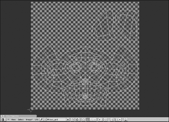
Figure 8-21 shows the unwrapped Suzanne head from before, after a bit of editing and adjustment.
So now you have an unwrapped mesh so the texture doesn't stretch on it. Woohoo! But say that, for some crazy reason, you don't want your object to have a checkerboard as a texture and you want to actually use this UV layout to paint a texture for your mesh. There are actually two ways to handle this: Paint directly on the mesh from within Blender, or export the UV layout to paint in an external program like The GIMP or Photoshop. I actually prefer to use a combination of these methods. I normally paint directly on the mesh in Blender to rough out the color scheme and perhaps create some bump and specularity maps. Then I export that image along with an image of the UV layout to get more detailed painting done in an external program.
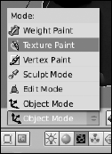
After you have an unwrapped mesh, the starting point for all of this is Blender's Texture Paint mode. Activate it by left-clicking the mode button in the 3D view's header, as show in Figure 8-22.
From here, things are pretty similar to Vertex Paint mode, with a few exceptions. The Transform Properties floating panel becomes a Paint Properties floating panel with a color picker and a Paint panel appears in the Editing buttons (F9), but the content of that panel is pretty different from the Paint panel that you have with Vertex Paint. The most striking difference is that you actually have a Brush datablock with definable attributes. With the Add New button at the bottom, you can actually define a texture for your brush, so you're not just painting flat colors. You define the brush texture in the Texture buttons (F6) like you set up any other texture. This gives your painting quite a bit more flexibility.
When you're in Texture Paint mode, start painting directly on your mesh by left-clicking and dragging your mouse cursor on it. If you have a test grid image already loaded on the image, you will begin painting directly on this image. In fact, if you still have the UV/Image Editor window open, you can watch the test grid image get updated as you paint your mesh. And actually, you can paint directly on the UV image itself by enabling painting (Image
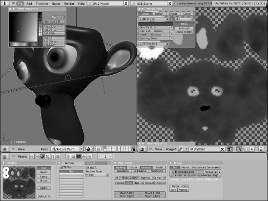
Because of this, when I paint textures in Blender, I like to have my screen laid out like Figure 8-23 shows. I have the 3D View and UV/Image Editor windows both in Texture Paint mode, whereas my Buttons window shows the Texture buttons (F6) for editing brush textures. It's a pretty effective way to get work done.
Of course, despite the cool things that you can do with Blender's Texture Paint mode, there are some things that you're better off doing in full-blown 2D graphics program like The GIMP or Photoshop. To work on your image in another program, you need to save the texture you've already painted as an external image. You should also export your UV layout as an image so you have a frame of reference to work from while painting. To save your painted texture, go to the UV/Image Editor and choose Image
With your image saved, the next thing you probably want is your UV layout. To export this, you need to run a script. You access it from the UV/Image Editor window while in Edit mode (Tab). Navigate to UVs
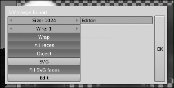
For now, leave all of these values at their defaults, with the exception of Size. For size, you want to use the same size that your texture image is. By default, the value is 512, but if your texture image is 1024×1024, like the default test grid is, you should change this value to 1024. When you left-click the OK button, a File Browser window appears, allowing you to save your UV layout to your hard drive as a Targa image. With the UV layout exported, you can load both of these images (the saved texture and the exported UV layout) as layers in your image editing program and proceed to paint the exact texture you want to use on your mesh. You may even paint separate textures for bump maps or specularity maps.
There's another benefit that unwrapping your mesh gets you: render baking. Render baking is creating a flat texture for your mesh that's based on what it looks like when you render it. What good is that? Well, it's really useful to people who wish to create models for use in video games. Because everything in a game has to run in real time, models can't usually have a lot of complicated lighting or highly detailed meshes with millions of vertices. To get around this, you can fake some of these effects by using a texture. And rather than paint on shadows and detail by hand, you can let the computer do the work and use a high resolution render instead.
Although this technique is used a lot in video games, it's also helpful when creating models that will be animated for film or television. If you can create a model that looks really detailed, but still has a relatively low vertex count, your rendering and animating process goes faster. Another use is for texture painters. Sometimes it's helpful to have an ambient occlusion or shadow texture as a frame of reference to start painting a more detailed texture.
Alright, so how do you create these textures? Well, the magic all happens in the Bake panel of the Render buttons (F10). This panel is shown in Figure 8-25.
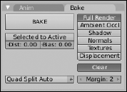
As the figure shows, you have six different kinds of images that you can bake out:
Full Render: This is the whole mess — textures, vertex colors, shadows, ambient occlusion, specular highlights — the works.
Ambient Occl: Ambient occlusion, or AO, is an approximated form of global illumination, or the effect that happens from light bouncing off of everything. If you have AO enabled in the World buttons (F8), the results of it can be baked by enabling this button.
Shadow: Any shadows that fall on this object are baked out as a texture.
Normals: A normal map is similar to a bump map, but instead of just using a grayscale image to define height, normal maps can get even more detailed by using a full color image to define height as well as direction. Artists who like to use Sculpt mode bake the normals from their sculpted mesh to a low-resolution version of the mesh to get details on the model without the additional geometry.
Textures: This option takes all of the textures you've applied to the mesh, both image-based and procedural, and flattens them out to a single texture.
Displacement: Baking displacement is similar to baking normals. The difference is that normal maps just redirect surface normals to provide the illusion of more geometry, whereas a displacement map can actually be used to move geometry around and create real depth on the surface of the object. Using displacement maps in Blender can be computationally expensive. However, a few third-party rendering engines have a nice way of handling displacement maps without the need to heavily subdivide your mesh.
After you have an unwrapped mesh, the steps to bake a new texture are pretty straightforward. Create a new image in the UV/Image Editor (Alt+N) at the size you want the texture to be and just choose the type of texture that you'd like to bake out from the Bake panel. After you've done that, left-click the Bake button and wait for the texture to be generated.
That said, if you want to use a high resolution sculpt as the basis for a normal map on a lower-res mesh, you need to do a couple of extra steps to get it to work properly. The workflow goes something like this:
Model your object using multires and Sculpt mode.
When you're done sculpting, you should have a few levels of multires.
Duplicate your object, but don't move it from its current location (Shift+D
It may be helpful to move this copy to another layer to temporarily get it out of your way (M
Select the original object and unwrap it at its lowest multires level.
It doesn't have to be the absolute lowest level, but it should be the level that you intend on rendering and animating with.
Add a new image in the UV/Image Editor (Alt+N).
This image should be the size of the texture you want to bake to.
Select (right-click) the duplicated, high-resolution version of your object and then add the low-resolution version to the selection (Shift+right-click).
This makes the low-resolution version of the mesh your active object.
In the Bake panel of the Editing buttons (F9), left-click the Selected to Active button.
This tells Blender that you want to take the detail of the high-resolution mesh and bake it as a texture for the low-resolution mesh.
Choose Normals as the type of texture you'd like to bake.
When you do this, a drop-down menu button appears on the left side of the panel. The options in this menu let you define the Normal Space that you would like to bake. The one you want to choose is Tangent.
Left-click Bake.
When you're done, you can save your freshly baked normal map to a file on your hard drive. Done!
After you have a bunch of UV textures created, either from painting them yourself or by baking them from the mesh, you need a way to bring them back into Blender. This is where Image textures in your Texture buttons (F6) come in. Figure 8-26 shows the Texture buttons with image textures on two different channels, one for a color map and another for a bump map.

The process for adding an Image texture is pretty similar to adding any of the procedural textures:
Choose Image from the Texture Type drop-down list in the Texture panel.
In the Image panel, left-click the Load button.
This opens a File Browser window where you can find the image you want to load as a texture.
With the image loaded, left-click the Clip button in the Map Image panel.
This isn't a critical step, but it's something I like to do. Basically, it prevents the image from tiling. Because this is a UV texture, I don't need it to tile.
Bring up the Material buttons (F5) and left-click the UV button in the Map Input panel.
This tells the material to use your UV layout for texture coordinates to properly place the texture. Even if the image isn't the original one you painted in Texture Paint mode, as long as you painted the texture using the UV layout as your reference, it should perfectly match your mesh.
In the Map To panel, choose the material attributes you want the texture to influence.
If the texture is just a color map, left-click the Col button. If it's a bump map, left-click the Nor button, and so on.
Repeat steps 1–5 for each texture channel that you want add a UV image texture to.