When it comes to character animation, a character is often a single seamless mesh. This makes it virtually impossible to animate that character with any detailed movement using the object animation techniques in Chapter 10. I mean, you can move the whole character mesh at once from one location to another, but you can't make the character smile or wriggle her toes or even bend her arms. You could break the mesh apart and use a complex set of parenting and constraints, but then you lose the nice seamless nature of the mesh.
What you really want to do is find ways to animate specific parts of the mesh in a controlled way without tearing the mesh apart. To do that, you need to create a rig for your character. A rig is an underlying structure for your mesh that allows you to control how it moves. It's an integral part of modern computer animation and, if it's done well, it makes the life of an animator monumentally easier. Think about it like turning your 3D mesh into a remote control puppet. This chapter explains the various tools and techniques used to create rigs. Then you can create a rig for nearly any object in Blender and have a blast animating it.
If your mesh, whether it's a character or a tree or a basketball, is to be animated in a detailed way, it has to deform from its original shape to a new and different shape. If you know what this new shape looks like, you can model it ahead of time. As an example, say you have a cartoony character, maybe the head of a certain monkey. You know that you're going to need her eyes to bulge out because all cartoon characters' eyes do this. To do this in Blender, you create a shape key, sometimes called a morph target in other programs. A rough outline of the process goes something like this (the next section in this chapter goes into more detail):
Start with your original mesh.
Edit the vertices of the original mesh without creating new geometry to the new pose you want to use.
In our example, you would model the character's eyes all bulgy. (Yes, bulgy is a real word. I think.)
Record this new arrangement of your vertices as a shape key to be used later when you animate.
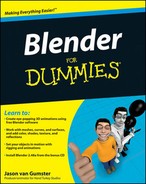
So that's the general example, but where are the actual controls? They're in the Editing buttons (F9) in the Shapes panel. Figure 11-1 shows three different states for the Shapes panel. By default, it looks pretty innocent and empty with just the one Add Shape Key button. However, when you left-click that button, you get buttons to control the Basis shape, or the original shape that other shape keys relate to. Left-clicking the Add Shape Key button a second time gives you another set of controls that controls the change from the Basis shape to this one, named Key 1.
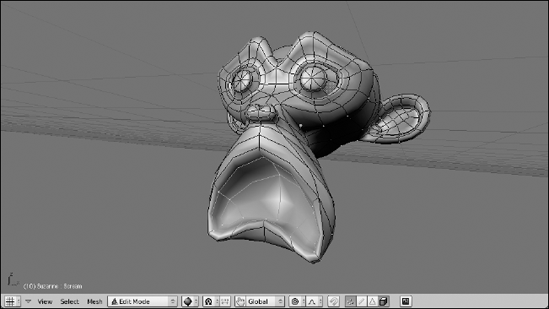
The best way to see how all of this works is to go through a practical example. Staying with the "bug-eyed monkey" theme, use Suzanne as your test subject, and go through the following steps:
Start with the default scene and delete the cube (Ctrl+X, right-click the cube, X).
Add Suzanne, give her a Subsurf modifier, set her smooth, and rotate her 90 degrees around the X-axis (spacebar

Change to the front view (Numpad 1).
Add a shape key (F9
For quicker access, you can use the I
Tab into Edit mode and change the mesh to have bulged eyes.
Be sure that as you do this, you do not add any extra vertices to the mesh. The shape should be defined by moving around the vertices you already have. A quick way to get make Suzanne's eyes bulge is to move your mouse cursor over each eye and press L to select just the vertices there. Then, with the Proportional Edit Tool (O) turned on, Scale (S) the eyes.
While still in Edit mode, add a new shape key (I
Now the Shapes panel should look like the last one in Figure 11-1. You've created Key 1. If you want, you can rename it in the Shapes panel by left-clicking its name field. I named mine "Eye Bulge."
Tab back to Object mode.
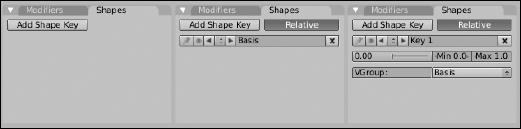
Figure 11-2 illustrates this process.
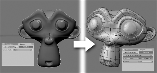
This process creates two shape keys, the Basis and Eye Bulge. Using the slider in the Shapes panel, you can smoothly transition from the Basis shape to the Eye Bulge shape. A value of zero means that Eye Bulge has no influence and you just have the Basis, whereas a value of one means that you're fully at the Eye Bulge shape. But here's where things get really cool. Notice the Min and Max values to the left of the slider. The Min is set to 0.0 and the Max is set to 1.0. Just for kicks, change the Max value to 2.0 and pull the slider all the way to the right. Doing this pushes your bulged eyes larger than your actual shape key made them. Now change the Min value to −1.0 and pull the slider to the left. Now Suzanne's eyes pinch in to a point smaller than the Basis pose. Figure 11-3 shows the results of these changes. This is a great way to provide even more extreme shapes for your characters without having to do any additional shape key modeling. How's that for cool?
From this point, you can create additional shape keys for the mesh. Say you want to have a shape key of Suzanne's mouth getting bigger, like she's screaming because her eyes have gotten so huge. If that's the case, the first thing you want to do is switch back to the Basis key. To do this, use the left/right arrows next to the key's name in the Shapes panel. You can also left-click the up/down arrow button and choose Basis from the list. The reason for doing this is because unless you're doing something special, it's a good idea to have most of your shapes based on the Basis. Otherwise, you may end up accidentally over-amplifying a shape key or nullifying it. When you're back at the Basis key, the process is about the same as before:
Tab into Edit mode and model the mouth open with the existing vertices.
One thing to note here is that you're not really touching Suzanne's eyes. You're just editing the mouth to get bigger.
While still in Edit mode, add a new shape key (I
Feel free to name this key whatever you want. I called mine "Scream."
Tab back into Object mode.
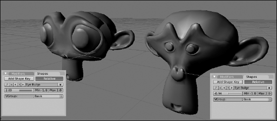
Figure 11-4 shows the results of this process.
Now that you have the Scream shape key, you can freely mix it with the Eye Bulge shape key or you can have Suzanne screaming with her regular, bulge-free eyes. The choice is yours. You have the flexibility here to mix and match your shape keys as it pleases you. And animating the mesh to use these keys is really easy. Split off an Ipo Curve Editor window from your 3D view and change the Ipo Type to Shape by left-clicking the drop-down button in the Ipo Curve Editor's header that says Object. You should notice that you have two animation channels here with the names you gave your shape keys. Scrub the timeline cursor forward in time and adjust the sliders in the Shapes panel. When you do this, new keys are added to the curves in the Ipo Curve Editor. Now you can freely scrub the timeline and watch Suzanne bulge and scream to your complete delight. Figure 11-5 shows a screenshot of me having exactly this kind of fun.

Now, you could do an entire animation using shape keys. But do I recommend doing that? No. There are other ways to control your meshes that may give you more natural movement for things like animating arms and legs. That said, shape keys are the perfect choice for things that can't be done with these other means (or, at least, that are very difficult). One big one is facial animation. The way parts of the face wrinkle up and move around is pretty difficult to re-create without modeling those deformations in. Furrowed brows, squinty eyes, natural-looking smiles, and phonemes, or mouth shapes for lip-syncing, are where shape keys shine. You can also team them up with other controls discussed later in this chapter to achieve cool effects like cartoon stretchiness, muscle bulges, and morphing objects from one shape to another.
Shapes work well for getting specific pre-defined deformations, but they can be pretty limiting if you want to have a little bit looser control over your mesh. It's also not as easy to use them on curve and surface objects. For these sorts of situations, we have another control mechanism: hooks. Hooks are a special kind of modifier that takes a set of vertices or control points and binds them to be controlled by another object, usually an Empty.
The workflow for adding a hook is pretty straightforward. You Tab into Edit mode and select one or more vertices or control points. Then you press Ctrl+H
Warning
You may try to find the Hook modifier as a selectable option in the list of available modifiers in the Modifiers panel. Don't look too hard; you won't find it. Because it requires you to actively select vertices or control points for the hook to control, the Hook modifier can only be added using Ctrl+H in the 3D View.
Tab back into object mode and transform the hook. When you do, all the vertices or control points that you assigned to the hook move with it. And with the options in the Hook modifier, you can control how much influence the hook has over these vertices or control points. The following example should give you a clearer understanding of this:
Start with the default scene in Blender (Ctrl+X).
Select the cube and Tab into Edit mode.
All of the cube's vertices should be selected by default. If they are not, press A until they are.
Do a multi-subdivide with four cuts (W
Select one of the cube's corner vertices (right-click).
Press Numpad+ a few times to increase the vertex selection.
Add a new hook (Ctrl+H
Tab back into Object mode.
At this point, behavior is as expected. If you select and move the Empty, all of the vertices that you assigned to the hook move with it, like they were parented to the Empty.
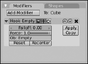
Increase the Falloff value in the Hook modifier to 2.0 (F9
Now when you select and transform the Empty, the way the vertices follow it is much smoother, kind of like when you're modeling with the Proportional Edit Tool enabled. For additional kicks, do the next step.
Add a Subsurf modifier to the cube and have it drawn smooth (Ctrl+1, F9
Now the transition is even smoother, as shown in Figure 11-7.

Tip
Does it bug you a bit that Blender placed the hook in the middle of your mesh? It would be easier to select if it were closer to the corner. Fortunately, the hook menu and modifier give you the option to do just that. There are two things that you can do. First, you can simply reposition the empty at a more acceptable location. And second, you can actually move the center of influence for the hook itself. The next example uses your smooth cube from before and does both of these things.
Select the cube and Tab into Edit mode.
Select the corner vertex of the cube that you selected in the last example.
Snap the 3D cursor to this vertex (Shift+S
Tab back into Object mode and select the Empty.
Snap the Empty to the location of the 3D cursor (Shift+S
This deforms the cube, but don't worry about that.
Select the cube again and Tab into Edit mode.
Clear the hook offset (Ctrl+H
Tab back into Object mode.
Now the hook performs like before, but with the Empty sitting outside of the mesh, making it easier to select and visualize.
Select the cube and left-click the Recenter button in its modifier options (F9
This sets the hook center to the same location as the Empty. Now when you transform the Empty, you have a slightly different sort of deformation that points directly at the Empty's center and looks quite a bit nicer, in my opinion. Figure 11-8 shows these steps visually.

The best use for hooks is for large organic deformations. Like shape keys, they're nice for creating muscle bulges and cartoony stretching. You can even use them along with shape keys. Because shape keys always use the same shape as the basis for deformation, adding a hook can give it a little bit more variety. For example, in the bug-eyed Suzanne example that you did for shape keys, you could add a hook for one of the eyes so it bulges more than the other one. It's touches like these that can give more character to your 3D characters.
Shape keys and hooks are great ways to deform a mesh, but the problem with them is that both are lacking a good underlying structure. They're great for big, cartoony stretching and deformation, but for a more structured deformation, like an arm bending at the elbow joint, the motion that they produce is pretty unnatural-looking. To solve this, 3D computer animation took a page from one of its meatspace contemporaries, stop-motion animation. Stop-motion animation involves small sculptures with a metal skeleton underneath them, referred to as an armature. The armature gives the model both structure and a mechanism for making and holding poses. Blender has the same thing and it too is called an armature.
To add an armature to your scene, go to the 3D View window and press spacebar
Now it's time to take that rather inauspicious single bone armature and do something more interesting with it. Like nearly every other object in Blender, you can edit it in more detail by selecting it (right-click) and Tabbing into Edit mode. In Edit mode, there are three things you can select: the sphere at the bone's head, the sphere at the bone's tail, and the bone itself. Selecting the bone body actually also selects both the head and tail spheres as well.

There are four ways to add a new bone to the armature:
Extrude: Select either the head or tail of the bone and press E to extrude a new bone from that point. This is the most common way to add new bones to an armature. If you add a bone by extruding from the tail, you get the additional benefit of having an instant parent-child relationship. The new bone is the child of the one you extruded it from. These bones are linked together, tail to head, and referred to as a bone chain. The Ctrl+left-click extrude shortcut for meshes and curves also works for bones as well.
Duplicate: Select the body of the bone you want and press Shift+D to duplicate it and create a new bone with the same dimensions, parent relationships, and constraints.
Subdivide: Select the body of the bone you want and press W
Use the toolbox: Press spacebar
Tip
Armatures can get very complex very quickly, so you should name your bones as you add them. Let me say that again: name your bones as you add them. The fastest way to name your bones is to use the Transform Properties floating panel in the 3D View (N), shown in Figure 11-10. Left-click the name in the Bone field in the right column of this panel and type a name for the bone that makes sense. For example, if you have a two-bone chain to control a character's arm, you may name one bone "arm_upper" and the other "arm_lower."
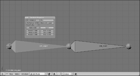
Blender has a pretty cool way of understanding symmetric rigs, or rigs that have a left side that's identical to the right. For cases like this, it's best to use a ".L" and ".R" suffix on your bone names. So in the previous example, if you are rigging a character with two arms, the bones in the left arm would be named "arm_upper.L" and "arm_lower.L". The right arm bones would be named "arm_upper.R" and "arm_lower.R". This gives you a couple of advantages, but the one that's most apparent when modeling is the X-Axis Mirror feature.
To understand this better, create a new armature at the origin (Shift+C
Tab into Edit mode on your new armature and change to the front view (Numpad 1).
Select the tail of the bone for this armature and extrude a new bone to the right (E).
Name this bone "Bone.R".
Select the tail of the main, or root, bone again and extrude another new bone, but this time to the left (E).
Name this bone "Bone.L."
In the Armature panel of the Editing buttons, enable the X-Axis Mirror button (F9
Select the tail of Bone.R and Grab it to move it around (G).
Now, wherever you move the tail of this bone, the tail of Bone.L matches that movement on the other side of the X-axis. In fact, you can even extrude (E) a new bone, and a new bone is extruded on both sides of the axis. As you might guess, this can speed up the rigging process immensely.
As you continue to build your armature, another pretty useful set of tools is in the Specials menu. You access it by pressing W in the 3D View. Two of the options in this menu are the Subdivide function and the Switch Direction function. As you may guess about the former, it takes the selected bones and creates more bones in their place, based on the number of subdivisions you would like to have. This is good if you've done something like make a character's spine a single bone and then later want to change that to two or three bones. The Switch Direction function is also pretty helpful. It prevents you from trying to do the same thing with an imprecise rotation.
Tip
When editing bones, it's a good idea to have the mesh you're rigging for visible. This way, you get your proportions correct. A good rule of thumb for placing bones is to think about where the character's real anatomical bones would be located. Then use that as your guideline to where to place the bones in the character's armature.
One of the important things that make armatures helpful is the notion of how its bones relate to one another. The most important of these relationships is the parent-child relationships between bones. The same hotkeys for parenting and unparenting objects also work with bones, but there are a couple additional features. To illustrate this, start a new scene (Ctrl+X), delete the default cube (X), add a new armature object (spacebar
Duplicate the single bone created and place it somewhere in space (Shift+D).
After you confirm placement (left-click), this new bone should be selected.
Add the original bone to your selection (Shift+right-click).
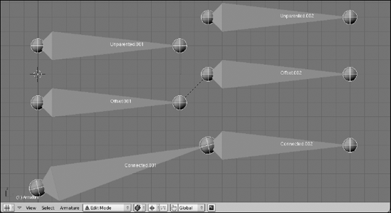
Press Ctrl+P to make the original bone the parent of the duplicate. When you do this, you are given two options:
Connected: Choosing this option moves the head of the child bone to the same location as the tail of the parent. This creates a bone chain as if you'd created the second bone by extruding it from the first.
Keep Offset: Choosing this option leaves the child bone in place and draws a dashed relationship line between the two bones. They're not connected, but one still has an influence on the other.
After you've created the parent relationship, select the child bone.
Clear the parent relationship by pressing Alt+P.
When you do this, you have another pair of options:
Clear Parent: Choosing this option removes any sort of parent-child relationship this bone has. This also means that if it was connected to the parent bone, it is now disconnected and can be moved around freely.
Disconnect Bone: This option doesn't actually clear the parent relationship. Instead, if you have bones that are connected, choosing this option maintains the parent-child relationship, but you can move the child bone independently of the parent. It would behave as if you made the parent by using the Keep Offset option.
Figure 11-11 shows two bones that are unparented, parented with an offset, and parented as a connected bone.
Tip
You may notice that even with bones parented – connected or otherwise – if you rotate the parent bone, the child does not rotate with it as you might expect in a typical parent-child relationship. This is because you are still in Edit mode, which is designed mostly for building and modifying the armature's structure. The parent-child relationship actually works in a special mode for armatures called Pose mode. You access this mode by pressing Ctrl+Tab. When you're in pose mode, if you select individual bones and rotate them, their children rotate with them, as you might expect. From there, you can swap back out to Object mode by pressing Ctrl+Tab again, or you can jump back into Edit mode by just pressing Tab.
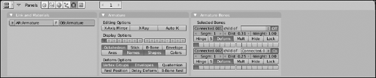
When working with armatures, the Editing buttons (F9) have some panels with options that are incredibly helpful. Select all the bones in your armature (A) and have a look at the Editing buttons. What you see should look like Figure 11-12.
Tip
Because the Armature Bones panel can display options for up to five bones at the same time, it may be a good idea to change your screen layout and put your Buttons window along the left or right side of the screen and display them vertically.
As you may have guessed, the Armature panel provides options for the Armature overall while the Armature Bones panel provides options for the currently selected bone or bones. Looking at the Armature Bones panel first, there are some options and controls that are immediately helpful. The first row of buttons lets you name your bone and define its parent. Rename the bone by left-clicking in the BO field and typing a new name. The drop-down menu to the right of the name field displays the selected bone's current parent, if it has one, and allows you to choose another existing bone as its parent. If you have a parent defined here, the Co button to the right of it allows you to tell Blender whether it's connected to its parent. These options change a bit between Edit mode (Tab) and Pose mode (Ctrl+Tab), so keep that in mind.
There are two other really important sets of buttons in the Armature Bones panel. The first is the Deform button. It's a simple toggle that tells Blender whether this bone will be used to directly deform geometry. A quick way of explaining it is that you can have bones that actually deform your mesh and bones whose purpose are to control the location of these deformer bones. Disabling the Deform button for those controller bones is how you prevent them from directly controlling your mesh's geometry.
The other really important buttons in the Armature Bones panel are those on the last row. These are bone layers. Just as you can place objects on layers in Object mode, Blender's armatures have a special set of layers to themselves. The reason for this is that character rigs with armatures can get pretty involved. Using bone layers is a good way to keep the rig logical and organized. Left-click on a layer button to assign the bone to it. If you would like the bone to live on more than one layer, you can Shift+left-click the layer button.
Notice that there's a corresponding row of layer buttons in the Armature panel. These buttons control which layers the armature is actually displaying. One thing to note is that unlike Blender's regular layers, these layers do not indicate whether they have anything in them, so you just have to keep track of where you place things.
Below the layer buttons in the Armature panel are a set of buttons for controlling how bones in the armature are displayed. A description of each bone follows:
Bone types: Only one of these four buttons can be enabled at any point in time. Note, however, that even though the bone type may not be drawn in the 3D View, the things it influences are still valid. That is, even if you're displaying Stick bones, they still control the same vertices within the range of the Envelope bones. Figure 11-13 shows examples of each of these bone types.
Octahedron: The default bone type. These bones are great for building a rig because they show which way the bone points and if it's rotated.
Stick: Draws the bones as a thin stick. I like to animate with my bones in this draw type so they stay out of my way while I work.
B-Bone: Bones are drawn as boxes and can be treated as simple Bézier curves. To make them deform more smoothly, increase the individual bones' Segm, or segment value in the Armature Bones panel. One thing to note is that even if you don't use the B-Bone drawtype, Blender still pays attention to the Segm value. So if your character deforms in an expected way, this may be why.
Envelope: Draw the bones with a scalable sphere at each end and a tube for the bone. Vertices within the influence area of these bones will be affected by them. Alt+S increases the bone's range.
Extra display options: All, one, or none of these controls can be enabled in any combination you desire.
Axes: Display the center axes of the bones. This is helpful for understanding their true position and orientation.
Names: Display the name of each bone in the 3D view. This can make selection and defining constraints much easier.
Shapes: To help communicate a bone's purpose to the animator, any bone in Blender can be replaced with any object in your scene. While in Pose mode, for a selected bone in the Armature Bones panel, you define the object you want by typing its name in the OB field. Enabling the Shapes button allows the replaced object to be seen in Pose mode.
Colors: To help organize bones in an armature for an animator, you can actually define custom colors for bones by using bone groups (explained later in this chapter in the section entitled "Making the rig more user-friendly"). Set all facial controls to blue, or the left side of the armature in red. Use whatever convention you care to and enable this button so you can make use of it.
Tip
Two other buttons I like to enable in this panel are X-Ray and Quaternion. The X-Ray button does the same thing that the X-Ray button in the Object buttons (F7) does. It allows you to see the bone in the 3D View, even if it's technically inside or behind another object. This makes your bones much easier to select when animating. The Quaternion button is more relevant after you begin animating with your rig, but enabling it makes the armature deform the mesh a lot more cleanly than if it's disabled.

Armatures and bones are pretty interesting, but they do you no good if they don't actually deform your mesh. If you've been using the last section as a guide for the tools to create your own rig, you might notice that when you Ctrl+Tab to Pose mode, you can Grab, Rotate, and Scale bones, but the moving bones have no influence whatsoever on your mesh. What you need to do is bind the vertices of the mesh to specific bones in your mesh. This binding process is commonly referred to as skinning. Blender has two primary ways of going about this: Envelopes and Vertex Groups.
Envelopes are the quickest way to get the mesh's vertices to be controlled by the armature. Nothing extra has to be created: It's just a simple parenting operation that seals the deal. To use envelopes to control your mesh, use the following steps:
In Object mode or Pose mode, select the mesh by right-clicking it and then add the armature to your selection by Shift+right-clicking.
Press Ctrl+P to make the armature the parent of the mesh.
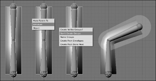
A set of options appears: You want to choose Armature. Immediately after you select the type of armature, you are prompted with a question about whether to make vertex groups. For this example, choose Don't Create Groups.
After you do this, when you Ctrl+Tab into Pose mode, the mesh should be under the influence of your armature.
To see this better, go to the Armature panel in the Editing buttons and enable the Envelope drawtype for the bones. This lets you see exactly where the influence of your envelopes really lie. And if some part of your mesh is not under the influence of an envelope, you can Tab into Edit mode and edit its size and influence.
That's the basic workflow for envelopes. Figure 11-14 illustrates this in action.
Now, envelopes are great for quickly roughing out a rig and testing it on your mesh, but for detailed deformations, they aren't ideal. Where the influence of multiple envelopes overlap can be particularly problematic, and there's a good tendency for envelope-based rigs to have characters pinch a bit at their joints. For these cases, a more detailed approach is necessary.
Tip
That said, using envelopes in your armature does give you one distinct control that you can't have with armatures otherwise. You can actually use an armature with envelopes to control the deformation of curves and surfaces. So long as a control point is within the influence space of a bone's envelope, it can be modified and therefore be animated with the armature.
So if envelopes are the imprecise way of controlling your mesh, what's the precise way? The answer is vertex groups. Chapter 10 briefly touches on vertex groups in reference to the use of the Child Of constraint. A vertex group is basically what it sounds like: a set of vertices that have been assigned to a named group. In many ways, it's a lot like a material index, as discussed in Chapter 7. Besides the fact that vertex groups don't deal with materials, there are a couple of distinctions between them and material indices. First of all, vertex groups are not mutually exclusive. Any vertex may belong to any number of vertex groups that you define. The other distinction is that a vertices can be given a weight, or a numerical value that indicates how much that particular vertex is influenced or dedicated to the vertex group. A weight of 1.0 means that the vertex is fully dedicated to that group, whereas a weight of zero means that the vertex may as well not even be part of the group.
To use vertex groups with armatures, you need to do two things first. First of all, like with envelopes, it's best that the mesh object is a child of the armature object.
Secondly, vertex groups need to have the exact name of the bones that control them. So if you have a bone called "pelvis," there should be a corresponding vertex group with the same name. The vertices assigned to that group then have their position influenced by the location, rotation, and scale of the pelvic bone. That influence is tempered by the vertices' weights.
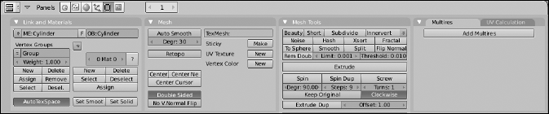
To adjust the assignments and weights of vertices in their respective vertex groups, you can use the Link and Materials panel in the Editing buttons (F9). All of the vertex group controls are on the left side of the panel, as shown in Figure 11-15. You create a new group with the New button and select the vertices that you wish to assign to the group. With the vertices selected, you can adjust the value in the Weight field and then assign them by left-clicking the Assign button.
Note
Something to note about vertex weights is that they are normalized to 1.0. That is, a vertex can be a member of two vertex groups and have a weight of 1.0 for both. In cases like this, Blender adjusts the weights internally so they add up to 1.0. So in my example, that double-grouped vertex behaves like it has a weight of 0.5 on both groups.
Of course, on a complex armature, this process of creating vertex groups and painstakingly assigning weights to each vertex can get excessively tedious. Fortunately, Blender has a couple tools to make things less painful. First of all, you don't have to create all of the vertex groups by yourself. Recall the process of skinning with envelopes. You have to parent the mesh to the armature there and, in doing so, you're presented with a few options, as shown in Figure 11-16. For using envelopes only, you choose Ctrl+P

Don't Create Groups: As the name says, this option does not create any vertex groups, thereby ensuring that the mesh is only influenced by the bone envelopes.
Name Groups: This option creates vertex groups for you using all of the bones that have the Deform button enabled in the Armature Bones panel. However, it doesn't automatically assign any vertices to any of the groups. Use this option if you want to handle assigning weights on your own. Without assigning any weights, the default behavior is to be controlled just by bone envelopes.
Create from Envelopes: This option is a bit of a compromise. It first creates the vertex groups based on the bones with their Deform option turned on. Then it looks at the influence area of the bone envelope and uses that to assign vertices to the group, with their weights varied accordingly. The advantage of this option is that it gets you weighted vertices. The downside, though, is that if the influence area of your envelopes isn't set up well, the weight assignment can look messy.
Create from Bone Heat: This is my favorite option to use. It works like the Create from Envelopes option, but instead of using the influence area of the bone envelopes to determine weights, it uses a more complex process that generally results in better vertex assignments and weights.
Regardless of which option you choose, you'll likely have to go in and manually tweak the weights of the vertices. And as you've noticed, trying to do that just from the Link and Materials panel can be pretty painful. Fortunately, there's a solution for that as well called Weight Paint mode. This mode is almost exactly like Vertex Paint mode, as described in Chapter 7, except that rather than painting color on the mesh, you're painting the weight assignment to a vertex group. To access Weight Paint mode, select the mesh (right-click) and press Ctrl+Tab. Even if you don't intend to paint weights, this is a great way to see how the weights were assigned by Blender if you used the Create from Envelopes or Create from Bone Heat options.
The way that weights are visualized is kind of like a thermal map where red is the hottest value and blue is the coldest value. Extending this logic to work with bone weights, vertices that are painted red have a weight of 1.0, whereas vertices painted blue are either not assigned to the vertex group or have a weight of zero. The 50% weight color is bright green.
After you're in Weight Paint mode, you get a new Paint panel in the Editing buttons (F9), as shown in Figure 11-17. Also like with Vertex Paint, if you have the Transform Properties floating panel visible in the 3D View (N), it changes to a Weight Paint Properties floating panel. This panel shares the same content as the Paint panel in the Editing buttons.

Some buttons in this panel are more interesting and helpful than others. The first of the useful buttons is the Wire button. Enabling this button overlays the mesh's wireframe on it. This is actually really helpful when weight painting because it helps you see where the actual vertices on the mesh are. That way, you're not just painting in empty space where no vertices exist.
The next button that's pretty helpful is the Vgroup button. This limits your paintable vertices to the ones that are already part of the vertex group you're working on. This way, you don't accidentally add a set of vertices on the other side of the mesh to the group you're working on while you try to tweak their weights. This is especially useful if you're trying to paint weights with a mouse, which can be a bit harder to control for painting than a drawing tablet.
I also love the X-Mirror button. It can literally cut your weight painting time in half. When you enable this button, Blender takes advantage of the left/right naming convention discussed earlier in this chapter and allows you to paint symmetrically. So if you're tweaking the vertex weights on the left leg, Blender automatically updates the weights for the corresponding bone on the right leg so that they match. If that ain't cool, I don't know what is.
The actual process of weight painting is nearly identical to painting colors with vertex paint. However, there is one other thing with weight painting, and that's the need to tell Blender which vertex group you're painting. There are two ways to do this. The slow way, you already know: Select the group from the Vertex Groups menu in the Link and Materials panel in the Editing buttons (F9). Of course, though, there's a faster way. That is to simply right-click the bone that you want to paint weights for. Doing that selects the bone and automatically switches to the corresponding vertex group in the mesh and allows you to paint it. Figure 11-18 shows a mesh in Weight Paint mode with some painting done on it. Because weight paint relies so much on color, I highly recommend you look at the corresponding full-color version of this image in this book's color insert.
Tip
If you choose to use vertex groups, you have something else to decide. Refer back to the Armature panel in Figure 11-12. At the bottom of the panel is a block of buttons under the heading of Deform Options. With both of the first two buttons, Vertex Groups and Envelopes, enabled, the mesh is influenced by both vertex groups as well as the bone envelopes. This can be useful in some instances, but I tend to prefer to work with just one or the other. And if I've created vertex groups and assigned weights to vertices, I generally disable the Envelopes button. Your rigging needs may be different, but this works for me because this way I know that the only reason a vertex is deforming improperly is that I didn't assign its weight properly. I don't have to concern myself with the influence of the bone's envelope.

As you may have guessed, rigging is a pretty intensive process. You need to be technically-minded and creative at the same time. The best riggers I've ever met are the sort of people who fit this description and have an eye for the big picture. These are the sort of people who enjoy playing Minesweeper, finding pleasure in solving the integrated relationships in each part of that game.
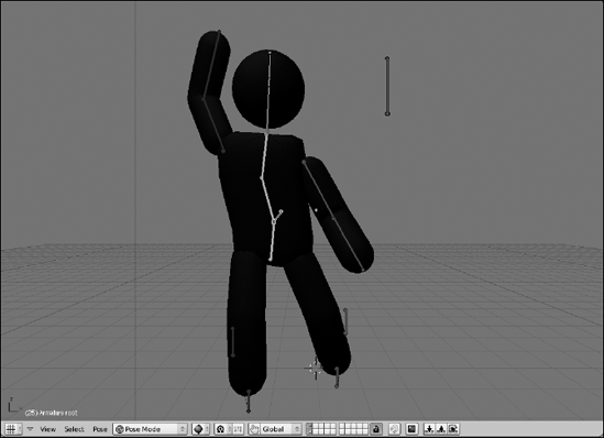
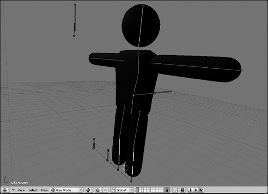
Well, regardless of whether you're one of these people, the best way to understand the full process of rigging is to actually create a rig of your own. The examples throughout the rest of this section are done with a simple stick figure character that I like to use for creating quick animations that test body language and timing. I love animating with stick figures, even in 3D. Ninety percent of an animated character's personality comes through in his body language. Animating with stick figures allows you to focus on that essential part of the process and keeps you from getting distracted with secondary details.
This stick figure, in both rigged and unrigged versions, is included with the CD-ROM that accompanies this book, so that you have a finished reference as well as a file to practice with. So you can have an idea of what you're looking for, Figure 11-19 shows the stick figure in a pose in the 3D View. Of course, if you have a character already modeled and want to rig it, that's great. You should be able use the techniques here for nearly anything you want to build a rig for.
If you load the stickman.blend file from the DVD, the first thing you might notice is his pose. He's standing up with his arms out to his sides. This is referred to as a T pose because the character looks like the letter T. This is probably the most common pose that modelers use when they create their characters and it's the most preferred pose for riggers. Some modelers may also model with the arms at the sides or somewhere halfway between the T pose and having arms at the side. There are valid reasons people give for any of these poses, but ultimately it really comes down to personal preference. I find that the T pose is easier for me to rig, so I have little bias for that one.
Now, time to get an armature in this mesh. Probably the best way to handle this is to create the centerline bones first. These would be the body bones, the head, and the hip bone. To do this, use the following steps:
Add your armature and start with the first body bone (spacebar
Enable X-Ray viewing for the armature (F9
Doing this ensures that you can see the bones of your armature, even if you're in the Shaded draw mode and the bones are inside your character's mesh.
Tab into Edit mode and move this bone up in the Z-axis until it's around Stickman's waistline (G
Select the tail of this bone and move it up in the Z-axis until it's at the top of the torso (right-click, G
Subdivide this bone into two bones (W
Name the bottom bone "body.1" and the top bone "body.2."
Select the joint between the two bones and move it back in the Y-axis a little bit (right-click, G
This helps the bones match the natural curvature of the spine a little bit better.
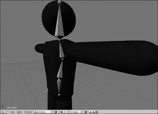
Select the tail of body.2 and extrude it up in the Z-axis to the top of Stickman's head (right-click, E
Name this bone "head."
Select the head of body.1 and extrude it down in the Z-axis to the bottom of Stickman's pelvis (right-click, E
Name this bone "hip." If you enable the Names and X-Ray buttons in the Armature panel of the Editing buttons (F9), you should now have something that looks like Figure 11-20.
The next step is to create bones for the arms and the legs. The way to do this is to create bones for half of the rig and then let Blender do the rest of the work for you by mirroring the bones. First things first, though — you have to create one half of the rig:
Switch to the front view and select the head bone and duplicate it, putting its root at Stickman's left shoulder joint (Numpad 1, right-click, Shift
Note that by doing it this way, the new bone is an offset child of the body.2 bone. Name this new bone "arm_upper.L."
Select the tail of arm_upper.L and move it to Stickman's elbow. It may help to press Ctrl to guarantee that the bone is perfectly horizontal (right-click, G
Extrude this tail to create a new bone along the X-axis that extends to Stickman's hand (E
Name this new bone "arm_lower.L."
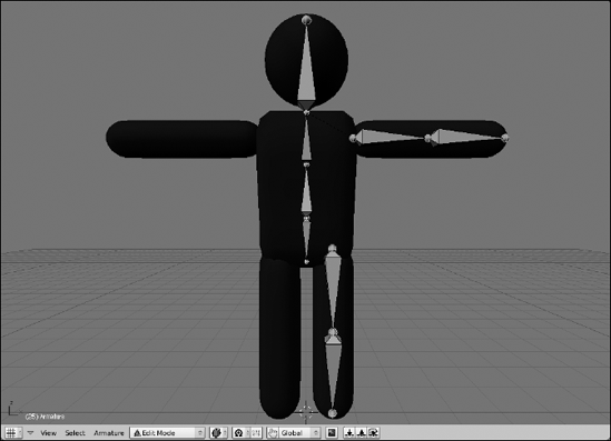
From the front view, select the hip bone and duplicate it, placing the new bone's head at the top of Stickman's left leg (Numpad 1, right-click, Shift+D).
Select this new bone's tail and move it along the Z-axis to Stickman's feet (right-click, G
Select this bone and subdivide it into two bones (right-click, W
Name the top bone "leg_upper.L" and the bottom bone "leg_lower.L."
Select the joint between these bones and move it forward in the Y-axis a little bit (right-click, G
This gives the knee a little bit of bend, which helps deformation later on.
Parent leg_upper.L to hip (right-click leg_upper.L, Shift+right-click hip, Ctrl+P
You should now have something that looks like Figure 11-21.
Now for the really cool part of letting Blender do the work for you. You want to select all of the bones that aren't on the centerline, duplicate them, and mirror them along the X-axis. The specific hotkeys and steps to do this are below:
Select both arm bones and both leg bones (B).
Duplicate the selected bones and immediately press Esc (Shift+D, Esc).
This places the newly created bones in the exact same location as their originators.
Switch to using the 3D cursor as your pivot (period [.]).
You should be building your armature around the Z-axis, so it would probably be a good idea to make sure your 3D cursor is at the origin (Shift+C).
Mirror these new bones along the X-axis (Ctrl+M
Switch back to using the median point as your pivot (Shift+comma [,]).
Have Blender automatically give these new bones the .R suffix to indicate that they're on the right side (W
Pow! All of your bones should be properly named now and your rig should now look like what's in Figure 11-22.

Figure 11-22. Stickman with a skeleton in him. He's almost rigged, but he still needs some controls.
What you currently have in place is the basic structure of the rig's armature. The primary function of these bones is to deform the character mesh. Technically, you could animate with just these bones after you skin them to the mesh. However, there are some additional bones that you can (and should) add to the armature to make it easier to animate. They work by taking advantage of the parenting set up by the bone chains and combining them with some reasonable constraints.
For example, you currently have a structured skeleton in place, but what happens if you Ctrl+Tab into Pose mode and Grab the body.1 bone and move it (G)? Because the entire upper body is directly or indirectly a child of this bone, the upper torso, arms, and head move with the body.1 bone. Unfortunately, the lower half of the body doesn't share this relationship, so as Figure 11-23 shows, you end up tearing Stickman's skeleton in half. Ouch!
To compensate for this, you need a bone that both the hip and body.1 relate to, binding the upper half of the body to the lower half. This is what you call the root bone. Moving this bone should move the entire armature. Adding this bone to the rig is pretty simple:
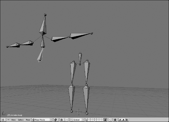
Figure 11-23. There's nothing relating the upper body to the lower body, so you can accidentally tear Stickman in half.
Tab into Edit mode on the armature and switch to the side view (Numpad 3).
Select the head of either the body.1 or hip bones (right-click).
Both heads are located in the same place, so it doesn't really matter which one you select.
Extrude a new bone in the Y-axis (E
You should move in the positive Y direction, towards the back of Stickman. Name this bone "root."
Select the body.1 and hip bones and then select the root bone (right-click, Shift+right-click, Shift+right-click).
Make root the parent of both body.1 and hip (Ctrl+P
This parent relationship means that you can move the entire armature by just selecting and moving the root bone. Before doing this, some people may choose to switch the direction of the root bone (W
Select the root bone and disable the Deform button in the Armature Bones panel (right-click, F9
This bone is intended purely to control the other bones. You don't want any of the mesh's vertices assigned to it. Your Stickman rig should now look something like Figure 11-24.

Figure 11-24. Adding a root bone to the rig prevents the top of the body from unnecessarily leaving the bottom.
Another convenient control bone that you may want to add is a head control. Sure, you can rotate the head bone as you wish, but often it's easier to use a bone as the head's (or eyes') target. That way, when you want the character to look at something, you just move the target bone to that something's location. An added benefit of this is that by doing it this way, you can successfully create complex moves, such as keeping the character looking at an object as he walks by it. Again, you could do this by animating the rotation of the head bone by itself, but this control certainly simplifies things for the animator. To do this, you just use a Track To constraint:
Tab into Edit mode and select the head bone (Tab, right-click).
Duplicate the head bone and move it in the Y-axis (Shift+D
The idea here is that you want the control bone to be far enough in front of the face so you can have some control without getting in the way of the rest of the rig. I moved mine about 3 Blender units out. Name this bone "head_target."
Clear the parent relationship on the head_target bone (Alt+P
Because the head_target bone came into being by duplicating the head bone, it inherited the parent relationship with the body.2 bone. You don't want that because you want to be able to move the head target independently of the rest of the rig.
Ctrl+Tab into Pose mode, select the head_target bone, and then also select the head bone (right-click, Shift+right-click).
Add a Track To constraint to this bone (Ctrl+Alt+C
This should automatically add a Track To constraint to the Constraints panel in the Editing buttons (F9). Chances are good that it also made the head bone rotate toward head_target and point directly at it. This is certainly not the behavior you want. To fix this, you need to change the alignment axes that the constraint works on.
In the Track To constraint, change the To axis to X and the Up axis to Y.
This should fix the head bone so it points in the proper direction. Now when you Grab (G) the head_target bone and move it around, the head bone always points at it.
Select the head_target bone and disable the Deform button in the Armature Bones panel (right-click, F9
Like the root bone, this bone is not intended to deform the mesh, so disabling the Deform button ensures this. Figure 11-25 shows what your rig should look like now.

Your Stickman is mostly functional now. However, there's another constraint that is a staple of nearly all character rigs and is monumentally helpful to animators. It's called an inverse kinematics, or IK, constraint. The next section goes into what this constraint does, how it works, and how to give your rig its benefits.
When it comes to animating characters in 3D with an armature, you have two ways to move limbs around: inverse kinematics and forward kinematics, or IK and FK. Kinematic is just a fancy way of saying motion. By default, your rig is set up to use FK. Say you have a bone chain and you want to place the tip of the last bone to a specific location in 3D space. In order to achieve this, you have to rotate the first bone in the chain, and then the next, and then the next, and so on until you can get that last bone's tip properly placed. You're working your way forward down the bone chain. Because of the parenting relationships between the bones, you can currently do this with your Stickman rig right now.
That's FK. It gets the job done, but it can be awfully difficult and tedious to try and get the tip of that last bone exactly where you want it. It would be nice if you could just grab that tip, put it in place, and let the computer figure out how all the other bones have to bend to compensate for that. This, basically, is the essence of IK. You move the tip of the last bone and Blender works backwards up the chain to get the other bones properly placed.
To see what this is like, select your Stickman armature and Ctrl+Tab into Pose mode. Now, select the body.2 bone and press G to Grab and move it. Notice that all it does is rotate. It doesn't actually change its location. Now go to the Armature panel of the Editing buttons (F9) and left-click the button that says Auto IK. This isn't a real IK constraint, but it will help you understand how IK works. Now Grab and move the body.2 bone. Notice that now, it moves around, and the body.1 bone rotates to compensate for the locations that you try to put body.2. Selecting the head bone or one of the arm_lower bones results in similar behavior. Click around and play with it. It's pretty cool. When you're done, disable the Auto IK button.
IK is really awesome stuff and it's very powerful, but it's not the ultimate solution for animating. See, one of the core principles of animation is movement that happens in arcs. Generally speaking, arcing movement is move believable and natural-looking. Things that move in a straight line tend to look stiff and robotic. Think about how a person's arms swing when they walk. It doesn't necessarily matter exactly where the hand is. The entire arm rotates and swings back and forth. That is FK movement. If you're animating, you can recreate that motion by keying the upper arm bone at the extreme ends of the rotation.
In contrast, IK movement tends to happen in a straight line. You're just keying the tip of the chain, so that tip moves directly from one location to the next. To recreate a swinging arm in IK, you'd need at least three keyframes: one at each extreme and one in the middle to keep the hand from going in a straight line. And even then you might need even more intermediary keys to try to get that smooth arc that you get automatically with FK.
Where IK shines is when the tip of the bone chain needs to be precisely positioned. A perfect example of this are feet. When a person walks, the feet must touch the ground. Trying to achieve this with just FK usually ends up with feet that look "floaty" and not locked into place as the character moves. Another example is if the character is holding on to something and doesn't want to let go of it. You want to keep the hand in place and let the elbow bend naturally. In instances like these, IK is really helpful. The biggest use, though, is for foot/leg rigs on characters. And to that end, you're going to use the following steps to add IK controls to the Stickman rig:
Tab into Edit mode on the armature and select the tip of the leg_lower.L bone.
You can actually select either the left or right bone. Because you have X-Axis Mirror enabled, whatever you do on one side also happens on the other.
Extrude a new bone in the Z-axis (E
You don't have to extrude the new bone very far. Just enough to know it's there. Name this bone "leg_IK.L," and make sure that the mirrored bone is named "leg_IK.R."
Disconnect leg_IK.L from leg_lower.L (Alt+P
Ctrl+Tab into Pose mode, select leg_IK.L, and add leg_lower.L to the selection (right-click, Shift+right-click).
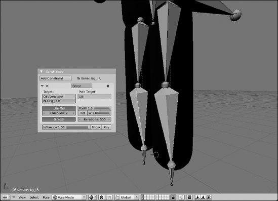
Add an IK constraint (Shift+I
This adds an IK constraint in the Constraints panel. Go to this panel and change the ChainLen value to 2. By default, the IK bone chain goes all the way back to the head of the hip bone. You actually only want it to have an influence to the head of the upper leg bone. Setting the chain length to 2 confirms this.
Perform steps 4 and 5 on leg_IK.R and leg_lower.L.
Sadly, X-Axis Mirror only works in Edit mode, so you have to add your IK constraints on both sides on your own.
Select the leg_IK.L and leg_IK.R bones and disable the Deform button for each of them in the Armature Bones panel (F9
Like the root and head_target bones, these are control bones and should not be used for skinning. At this point, you have a basic IK rig on your character's feet. It should look something like Figure 11-26.
Test your rig out by selecting the root and moving it around, particularly up and down the Z-axis. The leg bones in your Stickman rig should bend all by themselves to compensate for the location of the root bone relative to the IK bones. You can also select each of the leg_IK bones and move them around to control the bending of each leg independent of the other.
In doing this, however, you may notice that there are occasions where the legs don't quite know how to bend. They may randomly flip backward or roll out in odd angles. This is because, aside from slightly bending the rig at the knees when you created the leg bones, you haven't provided the legs with much of a clue as to how exactly they should bend. Fortunately, the solution to this is pretty simple. It's called a pole target. To define it, you need to create two more bones, one for each leg:
Tab into Edit mode on Stickman's armature and select leg_IK.L.
Again, because X-Axis Mirror is enabled and you're in Edit mode, choosing either leg_IK bone works fine.
Switch to side view, duplicate the bone, and move the new bone to somewhere in front of the knee (Numpad 3, Shift+D).
Name this bone "knee.L" and make sure the mirrored bone is named "knee.R."
Rotate knee.L 180 degrees in the X-axis (R
This step isn't essential. I just like to have my floating bones pointing up.
Parent knee.L to leg_IK.L (right-click knee.L, right-click leg_IK.L, Ctrl+P
Ctrl+Tab into Pose mode.
Select leg_lower.L and, in the IK constraint panel, enter Armature under the Pole Target field for OB. Enter knee.L in the BO field that appears after that.
Doing this defines knee.L as the pole target for the left leg's IK chain. When you do this, however, the knee joint for the left leg may instantly pop to the side, bending the leg in all kinds of weird ways. The next step compensates for that.
Still in leg_lower.L's IK constraint panel, adjust the Pole Offset value to −90.
This should cause the leg's knee joint to properly point at the knee.L bone. If it doesn't, try adjusting this until it looks correct. Usually this value is 0, 90, −90, or 180. The reason for this is because the default behavior is to point leg_lower.L's local X-axis toward the pole. If the local X-axis isn't forward, adjusting the offset accounts for this.
Perform steps 6 and 7 on leg_lower.R.
At this point, you have a fully configured IK rig for both of Stickman's legs. You're nearly ready to animate him. For reference, your rig should look like the one in Figure 11-27.

At this point, it should be pretty safe to skin the Stickman mesh to your armature. Using the bone heat method should give you the best results, so select the mesh (right-click), select the armature (Shift+right-click) and press Ctrl+P
At this point, you've got a great basic rig that you can start animating with immediately. However, you can make a few tweaks that make it even more usable. The first thing you can do is change the way the bones display in the 3D View. Now that you're done with the bulk of rigging, knowing which end of a bone is the head or the tail is a bit less important. Go to the Armature panel in the Editing buttons (F9) and change from Octahedron to Stick. Stick bones are the least obtrusive bones that are immediately available to you. Now you can see more of your mesh while you're animating and there's not as much clutter and geometry in the way. Figure 11-28 shows the Stickman rig with stick bones.
Another relatively new feature to Blender that is quite helpful for organizing your rigs is the ability to create bone groups. To do this, select the bones you would like to group together and press Ctrl+G. When you do this, you get four options:
Add Selected to Active Group: If you already have a group created and it's the one visible in the Link and Materials panel, choosing this option adds the selected bones to that group.
Add Selected to Group: Choosing this option gives you a second pop-up that gives you a list of your existing groups, as well as the ability to add a new group. Whichever you pick, the selected bones are added to it.
Remove Selected from Groups: If the bones you have selected are part of any groups, choosing this option removes them.
Remove Active Group: Choosing this option removes the group that is currently visible in the Link and Materials panel. Note that this does not remove the bones, just the group that they're associated with.
I used the bone groups feature to create groups for my main bone chains: left arm, right arm, left leg, right leg, and body. I left root, head, and head_target groupless. Create your own groups as you see fit.
Beyond organization, there's an additional benefit to using bone groups. You can define custom bone colors based on the bone groups you have. The control for this is in the Editing buttons. First, in the Armature panel, enable the Colors button under display options. Then, in the Link and Materials panel, left-click the button that says Default Colors and choose a Theme Color Set from the menu that pops up. I used this feature to make all of my left-side bones green and my right-side bones red. It's a good visual trick to let you or another animator quickly identify which bones are being used. Figure 11-29 shows what the bone groups and bone colors options look like in the Link and Materials panel.

Figure 11-29. The Link and Materials panel with controls for bone groups and bone colors for those groups.
Besides groups, another organizational tool for making your rig more usable are bone layers. Bone groups make it easy to visualize bones and even select them. However, bone layers are a faster, more reasonable way of showing and hiding the bones in your rig. As an example, have a look at Stickman's legs. They're entirely controlled by the IK and knee bones. Because you can see the Stickman mesh, you really don't need to see these leg bones. In some ways, they just get in the way of seeing your character's acting. In that case, it makes plenty of sense to move them to a different layer and hide that layer. To do this, use Shift+right-click, Border Select (B), or press L with your mouse over the leg bones to select the entire leg chain and then press M to move them to a different layer. I moved the bones to the first layer in the second block of layers. Now, if you ever want to see those bones, just go to the Armature panel and enable the layer there. In the meantime, though, as Figure 11-30 shows, your Stickman rig is much cleaner and now you're really ready to start animating.
