
Building models in 3D is as simple as building them out of clay, wood, or metal. Using 3ds Max to model something may not be as tactile as physically building it, but the same concepts apply: You have to identify how the model is shaped and figure out how to break it down into manageable parts that you can piece together into the final form.
Instead of using traditional tools to hammer or chisel or weld a shape into form, you will use the vertices of the geometry to shape the CG model. As you have seen, 3ds Max's Polygon toolset is quite robust.
In this chapter, we will tackle a more complex model with a children's Red Rocket toy. We will use the Editable Poly toolset, the Lathe and Bevel modifiers, and the Loft compound object to create the toy. We will also examine the use of QuickSlice (to add detail) and Booleans (to easily create interesting indentations on an existing surface).
Topics in this chapter include:
Building the Red Rocket
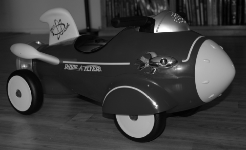
Using reference materials will help you efficiently create your 3D model and achieve a good likeness in your end result. The temptation to just "wing it" and start building the objects isstrong, especially when time is short and you're raring to go. This temptation should always be suppressed in deference to a well thought-out approach to the task. Sketches, photographs, and drawings can all be used as resources for the modeling process; you can place them in a scene as backdrop images and model over them. Not only are references useful for givingyou a clear direction in which to head, but you can use references directly in 3ds Max to help you model. Photos, especially those taken from different sides of the intended model, can be added to a scene as background images to help you shape your model.
Creating Planes and Adding Materials
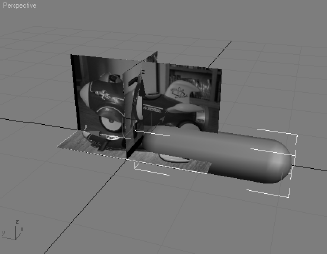
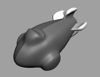
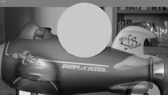
There are two common approaches to adding backdrop images for modeling in 3ds Max. You can use the viewport's Background Image feature or you can use the crossing boxes technique, which involves placing the reference images on crossing plane objects or thin boxes in the scene. In this exercise, we'll use the crossing boxes technique as the startingpoint to build a child's rocket ride-on toy, as shown in Figure 5.1.
Before you begin, copy the Red Rocket folder from the CD to your hard drive where you keep your other 3ds Max projects. Set your project folder to the Red Rocket project you just copied (File → Set Project Folder).
Open a new 3ds Max file by choosing File → New.
Go to the Customize menu → Units Setup. In the dialog box, set the units to Generic. Generic units are the 3ds Max's default units—one Max unit equals one inch.
Go to the Create panel to create a box (click the Geometry button (

Instead of creating the box with the click and drag method, we will use Keyboard Entry, as shown in Figure 5.2. Expand the Keyboard Entry rollout. Make sure the Perspective View is selected. Leave the XYZ parameters all set to 0; this will place the box at the origin point of your scene. Change the Length, Width, and Height parameters to the following and click Create:
Length: 22 Width: 0.05 Height: 12 When you click Create, 3ds Max will create the image plane we'll use for the side view. Rename the box01 object Side View.
Repeat steps 2 and 3 to create another flat box, which you'll use for the Top View image plane. Use the following parameters.
Length: 22
Width: 12
Height: 0.05
Rename the box Top View.
Activate the Front View, and then repeat steps 2 and 3 one last time to create the image plane for the front view of the rocket toy. Rename the box Front View.
Length: 12
Width: 12
Height: 0.05
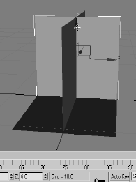
Move the Front View box up six units in the Z-axis to raise it so the bottom edge is directly on the Home Grid, as shown in Figure 5.3. Switch all the viewports to Smooth & Highlights (F3).
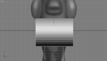
Navigate to the SceneAssetsImages folder in the Red Rocket directory that you copied to your hard drive. In this folder, you will find three reference JPEG images, one for each of the three image plane views we just created in the scene. Select the Top View reference image (called
TOP VIEW.jpg); drag it into the Top viewport in 3ds Max, and drop it onto the Top View image plane box. This will automatically place the image onto the box, so the image will be viewable in the viewport.Repeat the previous step to place
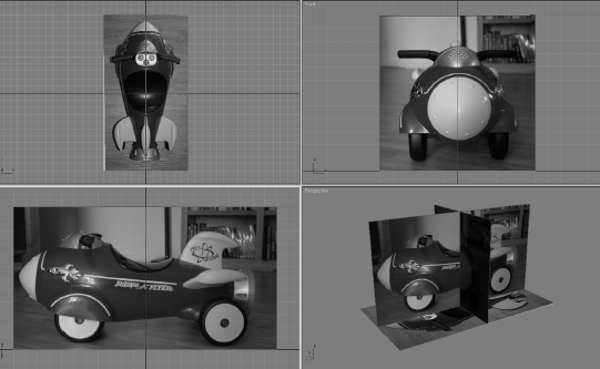
SIDE VIEW.jpg onto the Side View image plane in theLeft viewport and placeFRONT VIEW.jpg onto the Front View image plane in the Front viewport. Figure 5.4 shows the image planes with the reference images applied.Note
If, for some reason, the image on your Top View object seems to be the reverse of what is shown in the book, simply rotate the Top View object to correctly line it up the way the images appear in this chapter. You may also have noticed black bars appearing in the images. They are intended to allow the images to better line up with each other.
If you need to, adjust the placement of the Front View image plane so the proportions of the rocket match up. The bottom of the wheels and the top of the handlebars should line up in all three images. Just move the box using the Select and Move tool. You will need to use the Arc Rotate Viewport Navigation tool to rotate the view so that the image planes can be viewed from different sides to get them aligned.

Note
If the rocket images do not show up in the viewport after you drop them onto the boxes, make sure the viewport is set to Smooth & Highlights and try again.
Organizing Your Scene File
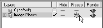
The next step is to begin organizing your scene file. We are going to use the Layer Manager (shown in Figure 5.5), which is a floating dialog window where you can organize objects into layers (something like Adobe Photoshop layers but for 3D objects).The objects you create have common properties for their associated layer including color, renderability, and display settings. An object can assume these properties directly from the layer on which you create it. Using layers makes it easier to manage the information in your scenes. For example, layers are often used to control the visibility of objects in a populated scene so you can focus on certain objects without the clutter of having the entire scene all visible at once. Layers can also control the color of yourobjects' wireframes and the frozen and hidden state of objects to better help you organize your scene.
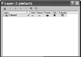
In the Layer Manager, when you create new layers, 3ds Max names them sequentially by default. These default names are Layer01, Layer02, and so on. After creating a layer, you should rename it something less generic so you can track your layers better. Click the layer in the Layer Manager to highlight the layer, and click again to change its name, ashown in Figure 5.6.
3ds Max assigns a random color to all new layers. You can accept the default settings or specify other colors by clicking on the little color swatch. For more on the Layer Manager see Chapter 3.
In the following steps, we will use the Layer Manager to organize our scene:
Select the image planes
On the main toolbar, click the Layer Manager icon (

In the Layer Manager, click Create New Layer (

If you create the new layer with the objects you want in the layer selected, they automatically will be added to the layer.
Now when we work in the scene, we do not want to select the image planes. There is no need to adjust them as you model. In the Layer Manager, this is made very simple. Click the Freeze icon next to the layer, as shown in Figure 5.7. The layer will be frozen so its objects cannot be selected in the viewports. The frozen boxes will turn gray, and the images will disappear.
Open the layer by clicking the plus sign. You will see the objects listed. Select all three image planes by holding down the Ctrl key and clicking the objects. Click the cube symbol next to one of the image plane names. This will bring up the Object Properties dialog box for that image plane box for that layer, as shown in Figure 5.8. In the Display Properties list, uncheck the Show Frozen in Gray box. When you press OK, the image will show up on the plane. Because all three objects were selected, this option was applied to all three.
Any objects you create will automatically be assigned to the selected layer, so in the Layer Manager make sure to click on layer0 (default) to set it as the current layer.

As you continue modeling the rocket, you will frequently use the Layer Manager to help manage the scene.

To begin the body of the rocket, you can load the scene file Rocket_00.max from the Scenes folder of the Red Rocket project. In the following steps, we will begin the rocket model:
Start in the Front viewport. In the Create panel, click the Geometry icon (

In the Modify panel set the capsule's Sides to 8 and Height Segs to 6. Uncheck the Smooth option; we will do the smoothing later.
Rename the capsule Rocket Body. Make Rocket Body see-through in all the viewports by pressing Alt+X in any of the viewports. This way you will be able to see the image plane through the geometry.
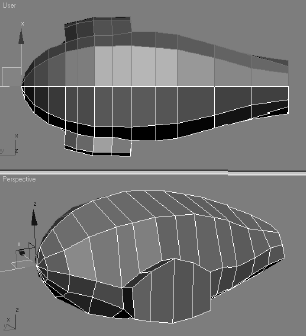
Line up the rocket body to the Side, Top, and Front image planes, matching the rocket body to the front end of the image as shown in Figure 5.10.
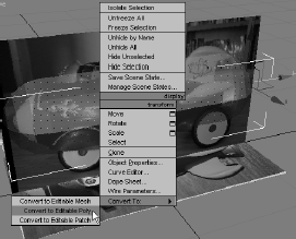
Center the pointer over the capsule to access the right-click menu, and choose Convert To → Convert to Editable Poly as shown in Figure 5.11.
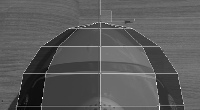
Enter the Vertex sub-object mode and select the vertex at the very front tip of the rocket body (as shown in Figure 5.12).
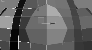
With the body selected, go into the Modify panel. In the Soft Selection rollout, click on Use Soft Selection and set the Falloff to 6.0. Now switch to the Scale tool (R). We need to scale along the XY-axis, which is a nonuniform scale. Do the scale in the Front viewport, center your cursor over the Transform gizmo's XY-axis as shown in Figure 5.13, and scale while watching the top view. Scale down to create a morepointed front.
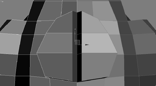
Selecting some of the front vertices section by section in the Top viewport, scale and/or move the rest of the front to match the front of the rocket in the Top Viewimage plane, as shown in Figure 5.14.
Using vertices with or without soft selection (using a Falloff setting if needed), shape the rest of the body to the shape in the three image planes (you can also look at Figure 5.16). Don't worry about the back end of the rocket body just yet; we'll tackle that in the next step.
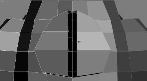
When you have the general shape of the body of the rocket, go into Polygon mode, select the polys at the rounded back end of your shape, as shown in Figure 5.15, and delete them by pressing Delete.
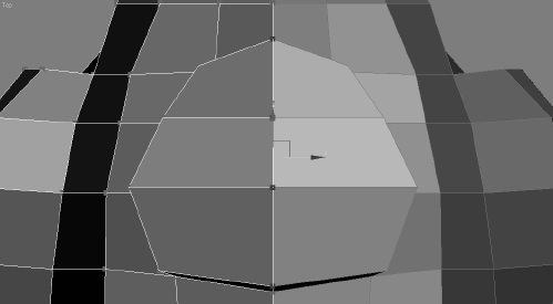
Figure 5.16 will show you the result of the deletion.


Smoothing the Body
The body looks very rough and chunky right now. To smooth out the rough model, we will use Subdivision Surfaces as we did on the hand exercise in the previous chapter. As we discussed earlier, a subdivision surface is a surface that has been divided into more faces while retaining the object's general shape. You subdivide to add more detail to an objector to smooth out the shape. In 3ds Max, Subdivision Surfaces is a rollout in the Modify panel for an editable poly.
The following steps will guide you through the process of smoothing out the rocket's body shape.
Go to the Modify panel to view the editable poly's parameters. Under the Subdivision Surface rollout, check the Use NURMS Subdivision box. This subdivides the polygons and relaxes the transition between polygons, smoothing the shape of the rocket's body. If you are still in Polygon mode, you will see the orange SDS cage appear. This cage allows you to continue editing the body's overall shape by just selecting the lower-res cage's polys and editing them. This lets you affect its broader form without having toselect many more polys of the smoothed version.
Enter Poly mode (press 4) with the rocket's body selected, select the polygons on one side of the rocket body's right side (as shown in Figure 5.17), and delete them.
Go to the top level of the editable poly (press 6). Go to the main toolbar and click on the Mirror tool (

Select the original side of the rocket and rename it Rocket Body ORIG. Select the reference side of the rocket that you just created and name it Rocket Body REF.
In the Layer Manager, create a new layer called ROCKET, and assign both halves of the rocket mesh to the new layer.
With Rocket Body REF selected, go to the Display panel (


Note
Freezing the reference half keeps you from accidentally working on the wrong half of the mesh.
Adding Detail to the Rocket Body
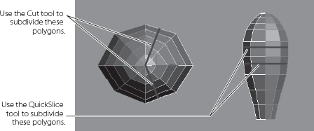
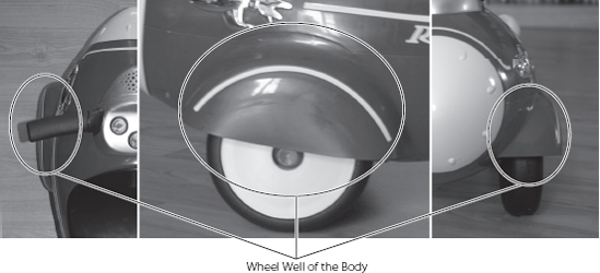
The wheel wells on the front sides of the body are the first details we will add to the body. To create the wheel wells, we need to add some more segments to the main body. To do this, we will use the Cut and Slice tools you used in the Hand and Dresser exercises in the previous chapter. You will be adding edges as shown in Figure 5.18 using the following steps.
Both the Cut and QuickSlice tool can be used in any of the sub-object modes. However, for the rocket's body, we will be in Vertex mode.
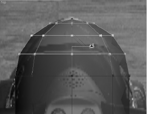
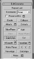
Go into the Layer Manager and hide the Image Plane layer. With the rocket's body selected, press the 1 key to enter Vertex sub-object mode. In the Modify panel, go tothe Edit Geometry rollout and select QuickSlice, as shown in Figure 5.19.
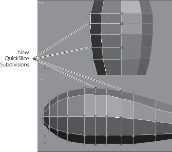
To create the new cuts, you will need to use both the top view and the side view. You will create one cut along the top and down the length, and two cuts from the top to the bottom of the rocket (as shown in Figure 5.18).
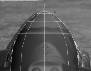
QuickSlice creates straight lines of edges only, so you need to click where you want the slice to begin, move the pointer to where you want the line to end, and click again. Use Figure 5.18 to show you where to create the division line. When you first click, you will see the slice before it is created. You can set the direction and location of the inserted edges by moving the pointer, so you can be sure the position of the slice is where you want. To stop slicing, you can right-click in the viewport or click Quick- Slice again to turn off the tool. Once you lay down the QuickSlice lines, your rocket shape will have new divisions, as shown in Figure 5.20.
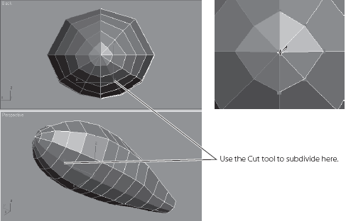
We will continue to add some detail using the Cut tool to where the wheel well detail will be added in the steps continued next. As you may recall from the Hand exercise in the previous chapter, the Cut tool works nearly the same way as QuickSlice. With the Cut tool, you can begin and finish the cut line at a vertex or at any point along an edge. The Cut tool also creates cuts from edge to edge in the same or another polygon.
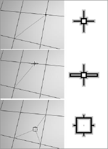
The Cut tool has three modes: cutting to a vertex, cutting an edge, and cutting a polygon. Each mode displays a different pointer, as shown in Figure 5.21. The pointer's ppearance will change according to where you click on the model.
Select the rocket's body. Select the Cut tool in the Modify panel under the Edit Geometry rollout, as shown in Figure 5.22.
Lay down a cut line along the body as shown in Figure 5.18 to create subdivisions in the model (Figure 5.23). (Remember that you are working on only the original side of the body.) The cut along the length of the body will start at the front at the vertex on the tip of the rocket (shown in the following graphic) and end between two vertices.
Creating the Wheel Well
You can continue with your own scene file (just make sure to turn off NURMS smoothing before you continue), or pick up and use the scene file Rocket_01.max from the Scenes older in the Red Rocket project that you copied to your hard drive.
Here are the steps to follow.
Select the Rocket Body ORIG mesh. Change to Poly mode (press 4) and select the three polygons in the middle of the body, as shown in Figure 5.25.
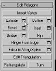
In the Modify panel under the Edit Polygons rollout, click the Extrude Settings button, as shown in Figure 5.26.
In the Setting dialog box, set Extrusion Type to Group and Extrusion Height to 0.8, as shown in Figure 5.27. Click OK.
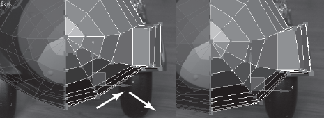
Now select all the polygons that were created with the extrude operation shown in Figure 5.28 (on the left). Right-click in the Front viewport to activate it, press the V key, and select Back View to switch to the Back viewport. In the Back viewport, use the Rotate and Move tools to align the polygons so that they line up with the wheel well in the Front View image plane as shown in Figure 5.28 (on the right). (You can switch back to the Front viewport at any time by pressing F.)
With Rocket Body ORIG still selected, switch to Vertex mode. Select and move the second row of vertices from the bottom of the rocket body out to the right and slightly down as shown in Figure 5.29. This evens out the bottom part of the body to give it a more rounded look. If we left those vertices where they were, that part of the body would appear lopsided. And who wants that?


Let's apply Subdivision Surfaces to the model again to see how the wheel wells looks when smoothed. There are still several things that we need to do to improve the look of he body. The wheel well polygons need to be moved down and reshaped to have an arch on the top. Select Rocket Body ORIG. In the Modify panel, turn on Use NURMS Subdivision under the Subdivision Surface rollout. Now, when it is subdivided, it looks a bit better. Figures 5.30 and 5.31 show the rocket before and after NURMS have been enabled for the mesh.

Now we need to hollow out the wheel well. Follow these steps.
Disable NURMS smoothing by turning off the Use NURMS Subdivision check box.
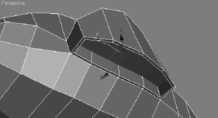
Enter Polygon Selection mode. Select the polygons at the bottom side of the wheel well, as shown in Figure 5.32.
Go to the Edit Polygons rollout in the Modify panel and open the Inset Settings button. Set the Inset Amount to 0.1 and click OK. Then, with the newly created inset polygons still selected, extrude them with an Extrusion Height of −0.7 to push in the area. Finally, delete the inside polygon.
We don't need to create the inside of the wheel well because we are not going to see it. We extruded into the wheel well in step 2 to make a solid lip at the wheel well, but it only needs to go halfway up.
Check to make sure that the new edges don't pokethrough the mesh (in Figure 5.33). If any do, select the vertex and move them inward.
Enable NURMS smoothing, and your rocket body hould resemble the one in Figure 5.34. Make sure o disable NURMS smoothing before you continue with the rest of the exercise.
Save your work.

Creating the Control Panel
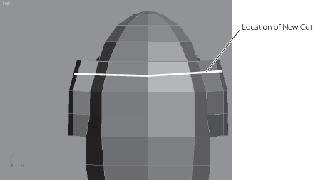
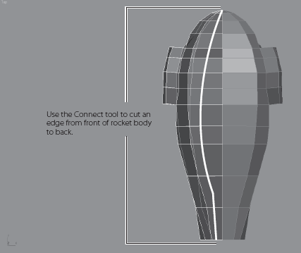
To create the control panel, we need to add one more cut along the top of the body for extra mesh detail, as you can see in Figure 5.36. To create this cut, we will try another method of creating new polygons: the Connect tool.
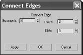
The Connect tool creates new edges between pairs of selected edges. In the Connect Edges Dialog Settings box, shown in Figure 5.37, you can specify the number of edges to be created. Using the Pinch and Slide values, you can define the spacing between those new edges.
Switch to Edge mode (press 2). In the Top wiewport, select the edge at the top center of the Rocket as shown in Figure 5.38. Go to the Modify panel, and in the Selection rollout, click on the Ring button. This selects all the edges from top to bottom.
Stay in Edge mode and in the Edit Edges rollout, select the Connect button. This adds a single new edge.
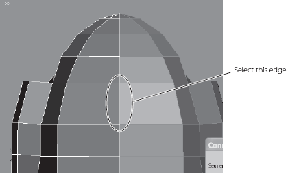
Now we are going to create a new cut line vertically down the length of the rocket body, as shown in Figure 5.39, using the same technique as in the previous exercise(the Connect tool).
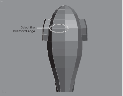
This time, select one of the horizontal edges at the top of the rocket (as shown in Figure 5.40). Then in the Selection rollout, select Ring to automatically select all thehorizontal edges above and below your initial selection. Go to Edit Edges and click Connect to create the new cut line shown in Figure 5.39.
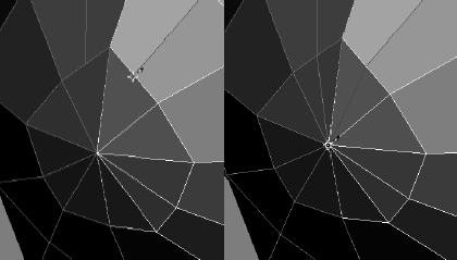
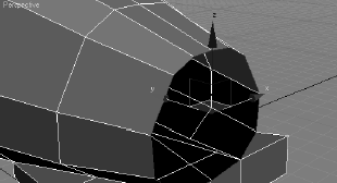
There is one little problem, however. The front end of the rocket doesn't connect to the newly added cut line. This is because the polygon at the tip, shown in Figure 5.41, does not have an edge for the new cut line to connect to, because all of those edges come to a point at the tip. We will continue the new cut line to the tip using the Cut tool in the next step.
Rotate the Perspective viewport so you can see the front end of the rocket clearly. Switch to Vertex mode and in Edit Geometry rollout, click the Cut tool. Center the cursor over where the new Connect Edge cut line ends and click. Then move to the tip of the rocket nose and click to finish the cut, as shown on the right in Figure 5.41.
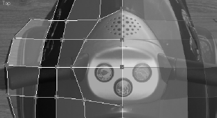
With the new vertices along this lengthwise cut line, in the Top viewport, move the vertices to fit the shape of the control panel as shown in the Top View image plane. See Figure 5.42.
Switch to Poly Selection mode and select the control panel polygons shown in Figure 5.43.
Go to the Edit Polygons rollout and click the Extrude Settings icon. Extrude the polys with an Extrusion Amount of 1.0 and with the Extrude Type set to Group.
If you look at the top view of the rocket, you will see the new extrude where it meets the reference half of the rocket body, as shown in Figure 5.44.
The two sides where you extruded should split away from each other. Remember that the two sides will eventually be stitched together to form the whole body, so all we need to do is make sure that all the vertices of the original side are aligned in the middle. For the original rocket half, you'll need to delete the polygons along the middle and move the vertices together. We'll do this in the following steps.
Select the middle inside polygons, as shown in Figure 5.45, and delete them.
Switch to Vertex mode, select the vertices shown in Figure 5.46. Move them along the X-axis to the middle, where the original and the reference halves meet, as shown in Figure 5.47. The problem is fixed! When the body halves are stitched together later, the body mesh will look seamless.
Switch to Vertex mode, and using the Front, Side, and Top viewports, move the vertices of the control panel to line up with the real rocket's control panel in the imageplanes, as shown in Figure 5.48.
Let's look at this rocket body smoothed. Go to the Subdivision Surfaces rollout and check Use NURMS Subdivision to smooth the model again. It should look like thegraphic shown in Figure 5.49.
Use the cage to further edit the control panel to better fit the real control panel in the reference image planes.


Note
You will see the Subdivision Surfaces cage as long as you are in Polygon mode.
When you exit NURMS Smoothing, the polygons for the control panel will seem exaggerated, as shown in Figure 5.50, and will go beyond the outlines of the real control panel in the image planes.
That is because the lower-resolution cage model is a rough shape before smoothing is applied to it. Once you re-enable smoothing, Subdivision Surfaces will smooth the detail down, shrinking it back from the cage's shape a little. With NURMS smoothing enabled, the control panel will look like Figure 5.51 and will fit the real model.


Creating the Back Wheel Axle
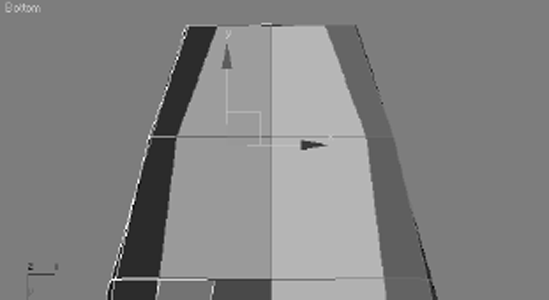
Disable smoothing by unchecking the NURMS option and switch to Polygon mode. Change your Top viewport to a Bottom viewport (press B).
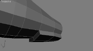
Select the two polygons at the back bottom of the body shown in Figure 5.53, and extrude them with an Extrusion Amount of 0.6.
The extruded polygons will split at the middle where the original and mirrored reference halves of the body meet, as they did with the control panel earlier in this exercise. Movethe vertices and fix the seam in the center the same way you did for the control panel.Make sure to delete the unneeded inside polygons as you did with the control panel. You can see the fixed result in Figure 5.54.
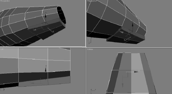
Go into Vertex mode and adjust the extruded polygons of the back axle so that they have the shape of the axle from the Side View image plane, as shown in Figure 5.55.
Select the polys on the side of the extruded polygons and extrude them with an Extrusion Amount of 0.6, as shown in Figure 5.56.
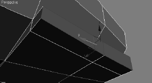
Rearrange the vertices to create a small delta wing coming off the bottom/side of the body, as shown in Figure 5.57.
Turn on Subdivision Smoothing again to see the smoothed results shown in Figure 5.58.
While still in NURMS Subdivision mode, try moving the cage vertices to sculpt the back wheel axle. Save your work.


The body is finished for now. Later we will create the seat and add the small lip that connects the thruster to the back.
Creating the Fins
The fins have specific features—rounded corners and edges—that require us to create them as a modified primitive. There is a nice dip in the wing and a bulbous rounded end;so we will need extra segments across the top. Follow these steps to create the fins.
In the Create panel, click the Create Geometry icon and select Standard Primitives from the drop-down menu. Click to create a Box primitive. In the top view over the wing on the image plane, click and drag to create a box with the following parameters: Length 4.5, Width 3.2, Height 0.4, Length Segs 4, Width Segs 4, and Height Segs 2.
Press Alt+X to make the model see-through (if it isn't already). Now you should be able to see the image plane under the box you just created for the side fin shown in Figure 5.60.
Select and rotate the box −16 degrees in the Z-axis to line up with the side fin. Convert the box to an editable poly and enter Vertex mode.
Using the Top viewport, move the vertices to match the fin in the Top View image plane, as shown in Figure 5.61.
On the side of the fin model, select the center row of vertices, go to the Edit Geometry rollout, and in the Constraints Group, turn on Normal. As shown in Figure 5.62, move the vertices, which are now constrained along their individual normal (meaning they will move only perpendicularly out from their current surface location), to create a nice round edge.
Select the vertices along the top and bottom rows at the edge of the fin model. The Constrain Group is still turned on for the Normal setting. Now move the vertices up along the X-axis, and they will move away from the center to create the bulbousrounded end of the fin (Figure 5.63).
Choose the row of vertices shown in Figure 5.64. (Make sure you select both rows on the top and bottom sides of the box.)
With Normal in the Constrain Group still turned on, move this set of vertices along the X-axis as you did in the previous step to increase the bulbous end of the fin, as shown in Figure 5.65. Move that row of vertices in the X-axis a little closer to the tip of the fin.
Select the row shown in Figure 5.66, and move the vertices closer to the tip of the fin to slightly narrow the bulbous end.
Enable NURMS smoothing for the fin as you did for the Rocket body mesh itself, and check your work against the fin shown in Figure 5.67. Remember to disable smoothingwhen you're done.
Note
To set up a hot key for NURMS Sub Division Surfaces, go to Customize Menu → Customize User Interface → Main UI → Nurms (Poly) and assign a hot key combination such as CTRL+ALT+N. As a general rule, it is best to learn the default UI before assigning any hotkeys.
Select the first fin and line it up to the body of the rocket on the side on which you are currently working. Select a copied fin, and move and orient it to line up with the fin on the other side of the body.
Select the third fin and place it on top of the rocket body as the vertical fin. Line it up with the images of the real rocket. Figure 5.68 shows you the fins placed on the rocket. Save your work.
The Scenes folder of the Red Rocket project has a completed fin model. The "Merging Objects into a Scene" sidebar discusses how to import a finished model into an existing scene and merge it with the current objects.


MERGING OBJECTS INTO A SCENE
Let's try to merge an external model into this scene. Pretend that you have created a fin model for the red rocket in a different scene file. You can import that fin into your current scene with the rocket body, instead of creating a whole new Fin object in this scene. In 3ds Max, this procedure is called merging.
Save your work.
Delete the three fins you've already created for your rocket.
Choose File → Merge and navigate to the Fin.max file in the Scenes folder in the Red Rocket project as shown here (below left).
Click Open. The Merge dialog window opens, as shown here (below right).

Select the Fin object from the dialog window and click OK. The Fin object will appear in your scene as the top center fin of the rocket.
Instead of creating the fins from scratch, you can clone and position the fin to create the side fins, or you can load your previous scene file and continue with the Rocket Model exercise. If you keep the merged fins, make sure to add them to the Rocket layer in the Layer Manager.
Creating the Thruster
You will create the thruster using the Lathe modifier technique, which you used tocreate the knobs for the dresser model in the previous chapter. Using a lathe works only when the object to be modeled is round and has the same look and detail all the way around. Like the dresser knob we created in Chapter 4, we will use splines—more specificallythe Line tool—to fashion the profile of the thruster. The Line tool in 3ds Max is like the Pen tool in Photoshop or the Mask tool in After Effects: it creates a 2D shape with no depth. The Lathe modifier then creates a 3D object by rotating that shape about one of the three axes (X, Y, or Z).
Using Lathe for the Thruster Shape
We need to identify the profile and draw it with the Line tool.
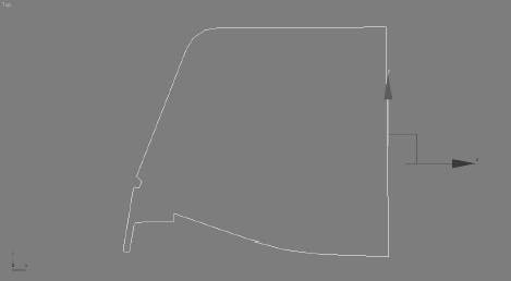
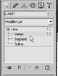
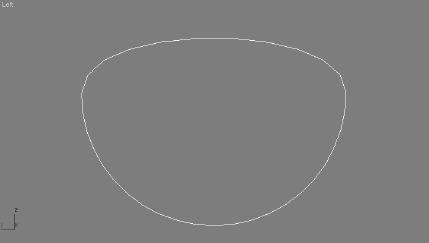
The profile shape we need to use is laid out in Figure 5.70. In the Create panel, click the Create Shapes icon. There you will find the Line tool button. Click Line and, in the Front viewport, lay out a profile similar in shape to Figure 5.70. The shape will makemore sense once you see it lathed.
Note
If you prefer not to create the shape, you can merge in an existing shape for the thruster's profile. Click File → Merge, navigate to the Scenes folder of the Red Rocket project, and openthe file called ThrusterProfile.
max. Select the Exhaust Profile Line object and click OK. The profile shape will merge into your scene.Once you have created the spline or merged the existing one into the scene, select the spline, go to the Modify panel, and add the Lathe modifier to the line.
Don't worry if you get something like the lathe shown in Figure 5.71, which is rotatingabout the wrong axis. Currently, the profile line is rotating about the axis at the center of the line shape. We need the axis of rotation to be at the inside edge of the profile shape.
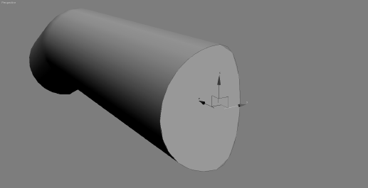
Go to the Modify panel and select the lathe to display its parameters. Under the Parameters rollout, in the Align section, click the Min button (shown in Figure 5.72). This moves the rotation axis for the profile to the inside edge.
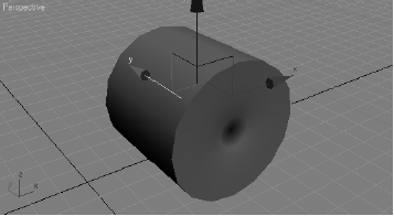
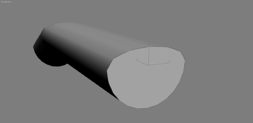
The lathed object should look more like the thruster but will have a big hole in the middle (Figure 5.73). This is also an axis issue. You need to adjust the axis of rotation of the lathe to get rid of the hole.
Go to the Modifier Stack, expand the Lathe modifier (click the plus sign to the left of the Lathe entry in the Modifier Stack), and select Axis. We now are in the lathe's subobject mode. Go to the Perspective viewport and move the Transform gizmo to the left until the hole is closed to the naked eye.
Note
Be cautious with step 4. You can't actually close the hole this way; you can only make it smaller. If you cross over the line, the normals will flip on the entire object. Get the hole assmall as you can; when the thruster is finished, you can add a Cap Hole modifier from the Modifier List.
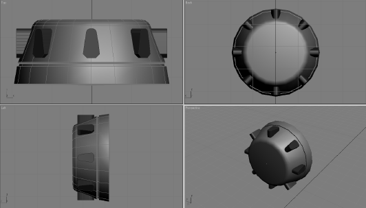
Go back to the Lathe parameters and change Segments to 20. This will help the thruster look less faceted than it does right now, but it will look a bit chunky on the edges. Don't be too concerned with that; the thrusters will not be seen that close in this scenario. Use the Segments parameter to make your lathes look only as smooth as needed for your shot, as shown Figure 5.74.
Name your thruster geometry Thruster, and add it to the Rocket layer in the LayerManager.
Move it to the back of the rocket body, according to the reference images.


Using Booleans for the Thruster Detail
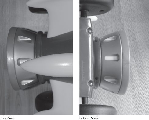
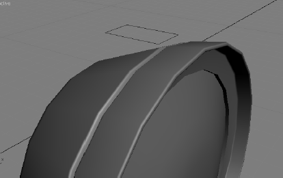
Take another look at Figure 5.69. The thruster has indented detail running around the side. We will create this in our model using a Boolean operation. A Boolean operation is a geometric operation that creates a shape from the addition of two shapes, the subtraction of one shape from another, or the common intersection of two shapes.
In theory, we will need to subtract the indented shape from the thruster mesh we have created so far. We'll start by creating the shape we need to use by cutting it out ofthe Thruster mesh. In Figure 5.69, you can see that the top of the shape indented into the thruster side has flat corners, the bottom corners are rounded, and the whole rectangle shape tapers.
You can continue with your own work or open Rocket_06.max in the Scenes folder of the Red Rocket project to catch up to this point.
Let's make the work area a little easier to navigate by hiding some of the rocket parts. Open the Layer Manager and click to hide the Image Planes layer, expand the Rocket layer, and click in the Hide column to hide the three fins. You can unhide them from the Layer Manager at any time.
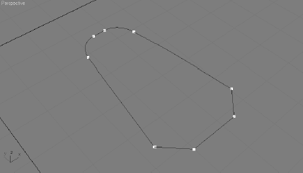
Go to the Create panel and, under Shapes, select Rectangle. Click and drag in the Top viewport to create a rectangle with Length 0.74 and Width 0.42. Move the rectangle above the thruster geometry we just lathed, as shown in Figure 5.75.
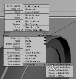
Center you cursor over the wireframe of the rectangle and right-click; choose Convert To → Editable Spline as shown in Figure 5.76. Converting to an editable spline will give you access to the sub-object modes, as you saw in the previous chapter, and it will let youedit the shape for the detail we need in the thruster.
Go into Vertex mode for the rectangle spline and select the bottom two vertices. Go into the Geometry rollout, enter a value of 0.04 for Chamfer, and press Enter Figure 5.77).
Select the two top vertices and move them closer together so that the rectangle tapersat that end. In the Geometry rollout, enter a value of 0.1 for Fillet. Click the Fillet button to round out the top of the cylinder, as shown in Figure 5.78.
Note
Watch carefully to make sure the chamfer and fillet in steps 4 and 5 don't create overlapping vertices. Too much of a good thing can cause trouble.
Exit Vertex mode by clicking on the editable spline in the Modifier Stack. When it is n sub-object mode, it is yellow. When it is at the top level, it is gray.
Note
If you don't want to create the splines, you can merge an already created spline from the scene file Thruster Detail Spline.max in the Scenes folder of the Red Rocket project.
With the spline selected, go into the Modifier List and choose Extrude. Set the Extrusion Amount to 0.4. We will use this to indent into the thruster sides.
Line up the Thruster Detail object to the thruster as shown in Figure 5.79.
There are eight indentations all around the thruster, so we are going to copy this one and array the indentation around the thruster eight times. To make it easier, move the pivot point of the Boolean object to the center of the thruster; this will enable the objectto be copied nicely around the thruster.
With the thruster selected, go to the Hierarchy panel (

We want to make sure the pivot is in the center of the exhaust. In the main toolbar, select the Align tool (

Note
The pivot should be the only thing that moves. If the object moves, Undo (Ctrl+Z) and try the step again.
Click Affect Pivot Only again to disable it. Press A to turn on Angle Snap. Change to the Rotate tool while holding down the shift key and rotate 45 degrees in either direction around the thruster dish. When you release the mouse button, the Clone dialog should open. Select Copy, enter a value of 7 for Number of Copies, and press OK.This will place seven copies of the object, each at 45 degrees of rotation around the thruster, making a total of eight Boolean objects that are 360 degrees around, as shown in Figure 5.80.
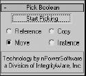
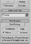
Select the Thruster, go to the Create panel, and select to create Geometry. In the pulldown menu, select Compound Object and select ProBoolean. Click the Start Picking button, as shown in Figure 5.81. Move to the Detail objects and click on each one to subtract from the thruster.
Note
If you don't want to spend time creating the Thruster Detail objects, you can merge the premade model from the scene
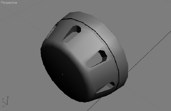
file Thruster Detail.maxin the Scenes folder of the Red Rocket project.Your thruster should now have the indentations shown in Figure 5.82.
Unhide the other parts of the rocket to see how everything looks so far. You can do this through the Layer Manager window. Save your work.


Further Body Work
We need to add some finishing touches to the body of the rocket. You can continue working with your own scene file or load Rocket_07.max from the Scenes folder in the Red Rocket project.
Select and delete the reference half of the body. You don't need it anymore.
Select the original body half and make sure Use NURMS in the Subdivision Surface rollout is turned on in the Modify panel.
Choose Symmetry from the Modifier List. This will copy the half of the rocket body to the other side. Depending on your settings, the rocket might disappear. If this happens, go to the Symmetry parameters in the Modify panel and, under Mirror Axis, choose X and check Flip.
You should see a seam running along the top middle of the body (Figure 5.83). To fix this, we need to bring those vertices in toward the center of the body until the seam disappears.
Select the vertices that run along the middle. Select and move a few at a time. Fromthe side view, you can see that those vertices stick up farther than the row below; this is what causes the ridge. Make the vertices level with the row of vertices below themby moving them along the Z-axis, as shown in Figure 5.84. (This step will be easier if you turn off the Use NURMS in the Subdivision Surface rollout.)
Go to Symmetry up in the Modifier Stack to view the whole body without the seam.Turn smoothing back on if necessary (Figure 5.85).


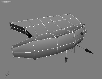
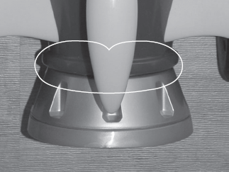
The next detail to manage is a small lip at the back end of the body (shown in Figure 5.86).We are doing the lip after we complete the body because this detail is easier to create after the body is stitched together. If you look in the Modifier Stack, the Symmetry modifier is on top and the Editable Poly modifier is on the bottom. If you go down a level to edit thebody through the Editable Poly modifier, the mirrored side will disappear. That won't make things easy, will it?
One way around this dilemma is to convert the entire object into an editable poly, which will permanently stitch the two sides together. Another option is to add another Edit Poly modifier over the Symmetry modifier and edit the two sides of the body that way. It's not advisable to collapse into an editable poly until the very end of the model process, so we are going to use the Edit Poly modifier instead:
Turn off smoothing if it's currently enabled. Also, hide the fins and the thruster.
Make sure the body is selected (with the Symmetry modifier). Go to the Modifier List and select Edit Poly to add the modifier to the rocket.
In the Edit Poly modifier, go into Borders mode and select the edge in the back of thebody, as shown in Figure 5.87.
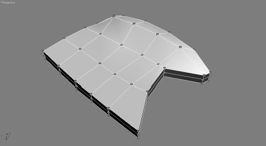
Go to the Edit Borders rollout and click Cap, as shown in Figure 5.88. This will create a poly where the hole was.
Switch to Poly mode and select the new polygon. Go to the Edit Polygons rollout and open the Bevel Settings dialog box. We will do four bevels through open the dialogbox. Between each bevel, make sure you click Apply and not OK. This will apply your bevel but keep the Settings dialog open for more.
Make four bevels with the following values:
BEVEL NO.
HEIGHT
OUTLINE AMOUNT
1st
0.05
0.3
2nd
0.2
0.1
3rd
0.2
−0.1
4th
0.05
−0.3
Click the Edit Poly name to go to the top level of the Edit Poly modifier.
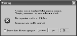
To see how the rocket body looks when it is smoothed, you will have to do something other than turning on NURMS in the editable poly for the body as you have been doing. If you click back to the Editable Poly entry in the Modifier Stack and try to turn smoothing on, you will see the Warning dialog box shown in Figure 5.89. You do not want to continue turning on smoothing this way.
If you click the top Edit Poly modifier in the Modifier Stack, and look for the Subdivision rollout, you won't find it. The Edit Poly modifier doesn't have that feature; it is available only in a converted editable poly. Until we collapse the model into an editablepoly, we will have to use another modifier: Turbo Smooth. Turbo Smooth is similar toSubdivision Surfaces in the editable poly, but it has fewer bells and whistles.
Select the rocket body and select Turbo Smooth from the Modifier List.
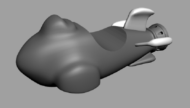
Unhide the exhaust and the fins. Make sure everything lines up, and render if you'd like (Figure 5.90). (See Chapter 11, "3ds Max Rendering," for more aboutendering.)


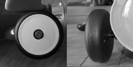
Making the Wheels
We are in the home stretch. The wheels, the handlebars, and the buttons for the control panel are all that are left to model. In this section, we will model the wheels, as shown in Figure 5.91.
You can continue with your own scene file or load Rocket_08.max from the Scenes folder in the Red Rocket project.
Note
If you don't want to create the wheels, you can merge the wheels using an already created model from the scene file Wheel.max in the Scenes folder of the Red Rocket project.
Creating the First Wheel
The wheels are created using the same general technique as the body and fins: Select the polygons of a standard/extended primitive and edit them. This time we are going to use a hamfer Cylinder.
If the Image plane is hidden, unhide it for the side view. In the Layer Manager, make sure the default layer is checked. This will ensure that the object you create for the wheel will not be in the layer that has the hidden Rocket objects.
Go to the Create panel. In the drop-down menu, select Extended Primitives and click to create a Chamfer Cylinder.
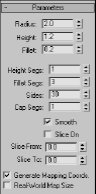
To get the side of the wheel to finish, click and drag the cylinder in the Side viewport. Go to the Modify panel and set the Chamfer Cylinder parameters as follows:
PARAMETER
VALUE
Radius
2
Height
1.2
Fillet
0.2
Height Segs
1
Fillet Segs
3
Sides
30
Cap Segs
1
Smooth
Checked
Slice
Unchecked
Set the parameters as shown in Figure 5.92.
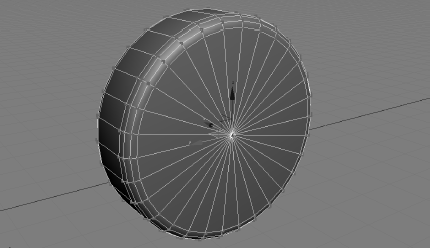
Convert the Chamfer Cylinder to an editable poly and go into Vertex mode. Select the vertex on the front in the center, as shown in Figure 5.93.
Go to the Edit Vertices rollout in the Modify panel and select the Chamfer Settings dialog box. Set the Chamfer Amount to 0.4 and click OK.
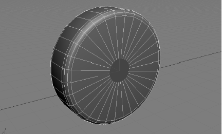
Switch to Polygon mode and select the new center polygon, as shown in Figure 5.94.
Go to the Edit Polygons rollout and open the Bevel Settings dialog box. Set Height to −0.4 and Outline Amount to 0.0, and click Apply to create one bevel. Then set Heightto 0.5 and Outline Amount to −0.12 and click OK to create a second bevel.
Now change the viewport so you can see the back of the wheel.
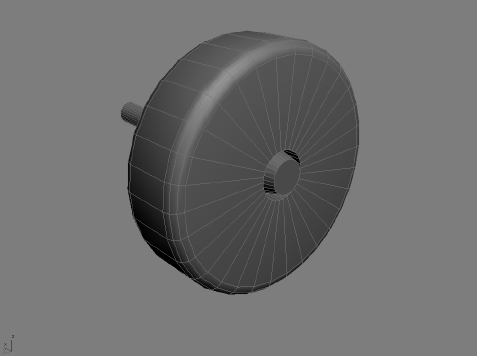
Go back into Vertex mode and select the center vertex. Go to the Edit Vertices rollout and click the Settings button for Chamfer. Set the Chamfer Amount to 0.2 and click OK.
Switch back to Polygon mode and select the new center polygon. In the Edit Polygons rollout, extrude the polygon with an Extrusion Amount of 3.0. You can see the completed wheel in Figure 5.95.
Placing the Wheels
One wheel is done! Now, make three clones for the front and back wheels. Place them at the wheel wells. Don't worry if the front wheels don't fit and penetrate the body. It was ard to tell how big to make the wheel wells until we had the wheels. We will fix that here:
In the Modifier Stack, click the Light Bulb icon next to TurboSmooth (Figure 5.96). This turns off the effect of the modifier.
The body of the rocket will appear low poly again, as you can see in Figure 5.97. It's usually easier to model in the low-poly version rather than the smoothed one.
Move down one level in the Modifier Stack to the Edit Poly modifier and go into Vertex mode.
Change any viewport to a bottom view. Select the vertices on the inside of the wheel well and move them to make the opening larger, so the wheels can fit, as shown in Figure 5.98.
Go back to the Modifier Stack and click the light bulb next to TurboSmooth to turn it back on. See if the wheels fit with the body when it is smoothed as shown in Figure 5.99.


Get a Handle on Things
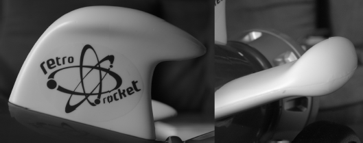
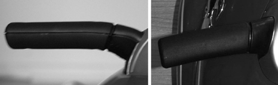
The red rocket has a pair of handles just as a bike does. They help keep the driver (usually a child) from face planting every time he or she gets on it. As funny as that may be, a parent can only watch it so many times. This is why most grownups find the handles (shown in Figure 5.100) to be the most important part of the rocket. We will model them now.
The handlebars will be created using a modeling technique called lofting, which creates a shape that is extruded along a path. Each handlebar is a compound object that uses one shape as a profile and another as the path to form a 3D surface or object.
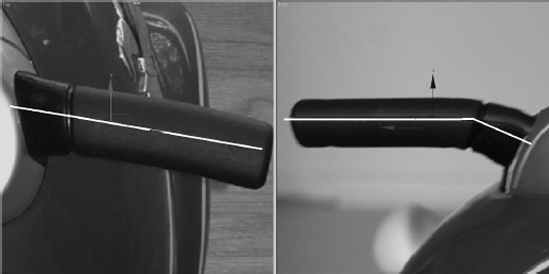
Creating the Path
Take another look at Figure 5.100 and imagine a straight line passing through the middle of one of the handlebars. This is the path we want to create.
You can continue with your own scene file or load Rocket_09.max from the Scenes folder in the Red Rocket project. You can hide the objects in the scene at this point to help keep an uncluttered workspace.
Start by going to the Create panel. Click the Create Shape icon and select the Line tool.
In the Back viewport, against the image of the front view of the rocket, click to place the line's first point where the handlebar meets the control panel. Move the cursor to where the handlebar has a bend in it and create another point. Place a final point where the handle ends, as shown in Figure 5.101, and right-click to create the line.
Move to the Modify panel and enter Vertex mode for the line, as shown in Figure 5.102. Select the middle vertex, go to the Line Parameters/Geometry/Fillet, and enter 0.1. This will add a smooth corner to the bend.
Note
Merge the scene file Handle Bar Spline.max from the Scenes folder of the Red Rocket project if you don't want to create the path yourself.
Creating the Shape
Now that we have the path for the loft, we need the profile shape, which is a cross-section of the handlebar. This shape is an oval with a flat top, as shown in Figure 5.103.
To create this shape, follow these steps:
Use the right-click menu to create a Circle shape from the Create panel and convert it to an editable spline.
Go into Vertex mode, select the top vertex, and delete it to flatten the top.
Next, we will create the Loft object.
Select the Handle Bar Path spline and go to the Create panel. Click to create geometry and select Compound Objects. Click the Loft icon.
Because we started the Loft process with the handlebar's path line, we only need to let 3ds Max know which shape to use. Go to the Creation Method rollout (Figure 5.104), and select Get Shape.
Select the handlebar shape in a viewport to use as the loft's shape.
Editing the Loft Object
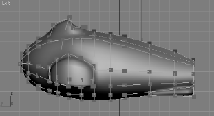
In Figure 5.105, you can see the loft's path and cross-section shape as well as the resulting Loft object.
In this example, the shape is rotated 90 degrees along the path, putting the handle on its side so to speak, as you can see in Figure 5.106.
The Shape needs to be turned to make the broad flat side point up, as shown in Figure 5.107.

To edit the loft, we will go into its sub-object mode. The sub-objects of a loft are the Path and the Shape.
Note
The original splines were instanced when the loft was created, so they are still connected to the loft. This means changes made at the sub-object level on the splines will be transferred to the lofted object. If necessary, you can alter the shape of the path line or shape splines and the loft will change accordingly. You cannot, however, move or rotate the path or shape splines to affect the shape of the loft. You must use Move or Rotate at the sub-object level of the loft instead.

Go to the Modify panel and select the Loft object.
Go into the Shape sub-object mode (Figure 5.108).
In a viewport, select the loft's shape at the end of the Loft object. The shape will turn red when it is selected, as shown in Figure 5.106. You should notice the shape spline is the smoother line in this figure.
Select the Rotate tool and rotate the shape on the loft −90 degrees. The entire loft will be updated as shown in Figure 5.107.
Adding Detail
The next step is to create the subtle curves and dips of the handlebars. The outside end of the real handlebar is curved. There is a groove toward the middle, and the handle tapers up where it meets the control panel. To look this good, the handlebar we've created needs more than one cross-section. With a Loft operation in 3ds Max, you can have any number of cross-sections for your loft, and they can be of varying shapes.
To edit a loft for these details, we are going to add more shapes along the path, and then edit those shapes to taste.
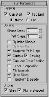
Go back to the top level of the loft in the Modify panel, and go to the Skin Parameters rollout. This is where you can manage the Steps (subdivisions) in the loft. By default, there is a value of 5 for both the Shape Steps and the Path Steps. The Shape Steps hereare fine, but the Path Steps value is too high. To fix this, turn Path Steps down to 1, as shown in Figure 5.109. If there are too many steps in your loft, it will get too heavy and dense to model.
Go back to Shape mode and select the shape. Take the cursor and center it over the Z-axis wire of the Transform gizmo that is connected to the shape.
We need to make copies of the Shapes so we can taper down the end of the handlebar. Shift+click and drag the gizmo to move the shape just a little bit up the body of thehandlebar to make a copy of the loft shape, as shown in Figure 5.110.
In the dialog box, choose Copy. Make three copies and place them close to the end of the handle, as shown in Figure 5.111. Switch to the Scale tool, and scale the outside shapedown 30 percent and the middle shape down 10 percent. Leave the last inside shape alone, which should create a nice curved taper at the end of the handlebar.
Select the inside shape on the loft, and make four more copies in a row close to where the bar curves (Figure 5.112). Select the two inside copies and scale them both down20 percent. This will create the groove toward the center of the handlebars.
Select the shape closest to the bend, and make a copy. Move it all the way to the otherend of the object, away from the tapered tip. This is where it will meet the body of the rocket. Select the Scale tool, and scale this end shape up 50 percent. Exit the Loft's sub-object mode.
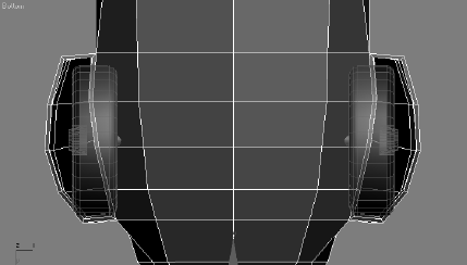
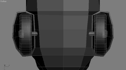
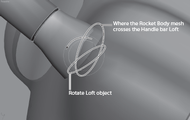
If any parts of the rocket are hidden, unhide them and see how the handlebars line up. You will probably agree that there is room for improvement (Figure 5.113).
Instead of rotating the Loft object, rotate the last shape at the end of the loft. Go back to sub-object mode and select the last shape to rotate to line up with the body, as hown in Figure 5.114.
Select the handlebar and mirror it for the other side of the rocket. Place it as needed. Figure 5.115 shows the rocket with its handlebars.


Note
If you prefer, you can merge the scene file Handle Bar.max from the Red Rocket project to complete the handlebars or check your own work.
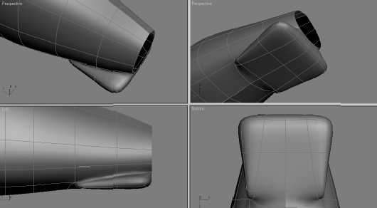
Hold onto Your Seat
What fun would it be to ride a rocket standing up? Speaking from experience, it's not fun. So let's give our rocket model a nice comfy seat. Then we'll be finished with the model!
You can continue with your own scene file or load Rocket_10.max from the Scenes folder in the Red Rocket project.
If you are using your own scene file and not
Rocket_10.max, in the Left view, create a cylinder with the following options.PARAMETER
VALUE
Radius
3
Height
8
Height Segments
1
Cap Segments
1
Sides
40
Smooth
Checked
Use the parameters shown in the dialog box in Figure 5.116.
From the side view, line up the cylinder so it is over the part of the rocket body where the seat would be (as shown in Figure 5.117).
From the top view, the cylinder should be evenly spaced on both sides of the rocket (Figure 5.118).
Select the rocket body, go to the Create panel, and click to create the geometry. Select Compound Objects from the menu and select ProBoolean. Choose Start Picking fromthe Pick Boolean rollout, and then select the Cylinder in a viewport. The cylinder willcut a seat into the rocket body as shown in Figure 5.119.
Note
Because the Boolean operation will collapse all the modifiers on the body, it is important that it be the last operation we perform on this model. We won't want to make any changes to thebody that would require access to its modifiers. Once any modifiers are collapsed, editingbecomes difficult.
Convert the rocket body to an editable poly by right-clicking on the Rocket Body object.
The control panel of the rocket needs some buttons. To add them, create a few Chamfer Cylinders and place them there. Now you're really done! Figure 5.120 shows the completed red rocket with buttons in the control console.
Save your work, but that is second nature to you by now—right?

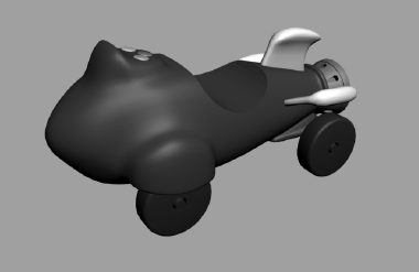
Unhide any parts of the rocket that you may have hidden to clear your workspace. Take it all in. As you can see, a fairly complex object is nothing more than a collection of simple shapes hammered, chiseled, cut, poked, and prodded into place. By learning how to dissect a complex object into its component shapes and learning how to view modeling an object as a series of steps, you will grow as a modeling artist.
Summary
When you built the red rocket, you employed several of the Editable Poly tools you learned about in the previous chapter. The more you use these tools, the faster they will become an instinctive part of your workflow. You also used the very handy Symmetry modifier to cut your work on the body in half.
After setting up the scene with background images, you were able to line up model parts and build them to fit the actual object as you worked in the scene.
In the next chapter, we will continue exploring the Editable Poly tools while creating a smoother, more organic model.