OpenGL ES is an application programming interface (API) for advanced 3D graphics targeted at handheld and embedded devices such as cell phones, personal digital assistants (PDAs), consoles, appliances, vehicles, and avionics. OpenGL ES is one of a set of APIs created by the Khronos Group. The Khronos Group, founded in January 2000, is a member-funded industry consortium that is focused on the creation of open standard and royalty-free APIs for handheld and embedded devices.
In the desktop world there are two standard 3D APIs, DirectX and OpenGL. DirectX is the de facto standard 3D API for any system running the Microsoft Windows operating system and is used by the majority of 3D games on that platform. OpenGL is a cross-platform standard 3D API for desktop systems running Linux, various flavors of UNIX, Mac OS X, and Microsoft Windows. It is a widely accepted standard 3D API that has seen significant real-world usage. The API is used by games such as the Doom and Quake series, user interfaces as in Mac OS X, workstation computer-aided design (CAD) applications like CATIA, and digital content creation applications such as Maya and SoftImage|XSI.
Due to the widespread adoption of OpenGL as a 3D API, it made sense to start with the desktop OpenGL API in developing an open standard 3D API for handheld and embedded devices and modifying it to meet the needs and constraints of the handheld and embedded device space. The device constraints that OpenGL ES addresses are very limited processing capabilities and memory availability, low memory bandwidth, sensitivity to power consumption, and lack of floating-point hardware. The working group used the following criteria in the definition of the OpenGL ES specification(s):
The OpenGL API is very large and complex and the goal of the OpenGL ES working group was to create an API suitable for constrained devices. To achieve this goal, the working group removed any redundancy from the OpenGL API. In any case where there was more than one way of performing the same operation, the most useful method was taken and the redundant techniques were removed. A good example of this is specifying geometry, where in OpenGL an application can use immediate mode, display lists, or vertex arrays. In OpenGL ES, only vertex arrays exist and immediate mode and display lists were removed.
Removing redundancy was an important goal, but maintaining compatibility with OpenGL was also important. As much as possible, OpenGL ES was designed such that applications that were written to the embedded subset of functionality in OpenGL would also run on OpenGL ES. The reason this was an important goal is it allows developers to leverage both APIs and develop applications and tools that use the common subset of functionality. Although this was an important goal, there are cases where it has deviated, especially with OpenGL ES 2.0. This is discussed in detail in later chapters.
New features were introduced to address specific constraints of handheld and embedded devices. For example, to reduce the power consumption and increase the performance of shaders, precision qualifiers were introduced to the shading language.
The designers of OpenGL ES aimed to ensure a minimum set of features for image quality. Most handheld devices have limited screen sizes, making it essential that the quality of the pixels drawn on the screen is as good as possible.
The OpenGL ES working group wanted to ensure that any OpenGL ES implementation would meet certain acceptable and agreed-on standards for image quality, correctness, and robustness. This is done by developing appropriate conformance tests that an OpenGL ES implementation must pass to be considered compliant.
There are three OpenGL ES specifications that have been released by Khronos so far: the OpenGL ES 1.0 and ES 1.1 specifications (referred to jointly as OpenGL ES 1.x in this book) and the OpenGL ES 2.0 specification. The OpenGL ES 1.0 and 1.1 specifications implement a fixed function pipeline and are derived from the OpenGL 1.3 and 1.5 specifications, respectively.
The OpenGL ES 2.0 specification implements a programmable graphics pipeline and is derived from the OpenGL 2.0 specification. Being derived from a revision of the OpenGL specification means that the corresponding OpenGL specification was used as the baseline for determining the feature set in the particular revision of OpenGL ES. A difference specification was then created that described the changes and additions to OpenGL ES versus the OpenGL specification from which it is derived.
As OpenGL ES 2.0 is derived from the powerful OpenGL 2.0 API, it enables extremely rich programmable game content. For example, the image in Color Plate 1 (see the center of this book) is from a demo of a pinball game targeted at OpenGL ES 2.0 and it uses shaders for advanced effects such as environment mapping and per-fragment lighting. This example demonstrates the kinds of effects that will be commonplace in OpenGL ES 2.0 applications. With OpenGL ES 2.0, much of the programmable graphics capabilities of desktop hardware are now available on embedded devices.
In the sections that follow we give an introduction to the OpenGL ES 2.0 pipeline.
OpenGL ES 2.0 is the API that we cover in this book. Our goal is to cover the OpenGL ES 2.0 specification in thorough detail (both the core specification and Khronos approved OpenGL ES 2.0 extensions), give specific examples of how to use the features in OpenGL ES 2.0, and discuss various performance optimization techniques. After reading this book, you should have an excellent grasp of the OpenGL ES 2.0 API, be able to easily write compelling OpenGL ES 2.0 applications, and not have to worry about reading multiple specifications to understand how a feature works.
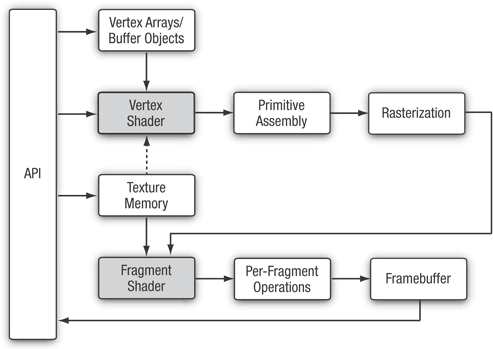
OpenGL ES 2.0 implements a graphics pipeline with programmable shading and consists of two specifications: the OpenGL ES 2.0 API specification and the OpenGL ES Shading Language Specification (OpenGL ES SL). Figure 1-1 shows the OpenGL ES 2.0 graphics pipeline. The shaded boxes in Figure 1-1 indicate the programmable stages of the pipeline in OpenGL ES 2.0. An overview of each stage in the OpenGL ES 2.0 graphics pipeline is presented next.
This section gives a high-level overview of what a vertex shader is. Vertex and fragment shaders are covered in depth in later chapters.
The vertex shader implements a general purpose programmable method for operating on vertices.
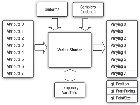
The inputs to the vertex shader consist of the following:
Attributes—Per-vertex data supplied using vertex arrays.
Uniforms—Constant data used by the vertex shader.
Samplers—A specific type of uniforms that represent textures used by the vertex shader. Samplers in a vertex shader are optional.
Shader program—Vertex shader program source code or executable that describes the operations that will be performed on the vertex.
The outputs of the vertex shader are called varying variables. In the primitive rasterization stage, the varying values are calculated for each generated fragment and are passed in as inputs to the fragment shader. The mechanism used to generate a varying value for each fragment from the varying values assigned to each vertex of the primitive is called interpolation. The inputs and outputs of the vertex shader are diagramed in Figure 1-2.
Vertex shaders can be used for traditional vertex-based operations such as transforming the position by a matrix, computing the lighting equation to generate a per-vertex color, and generating or transforming texture coordinates. Alternately, because the vertex shader is specified by the application, vertex shaders can be used to do custom vertex transformations.
Example 1-1 shows a vertex shader written using the OpenGL ES shading language. We explain vertex shaders in significant detail later in the book. We show this shader now just to give you an idea of what a vertex shader looks like. The vertex shader in Example 1-1 takes a position and its associated color data as input attributes, transforms the position by a 4 × 4 matrix and outputs the transformed position and color.
Example 1-1. A Vertex Shader Example
1.  // uniforms used by the vertex shader
2.  uniform mat4   u_mvpMatrix; // matrix to convert P from model
3.                              // space to normalized device space.
4.
5.  // attributes input to the vertex shader
6.  attribute vec4   a_position; // position value
7.  attribute vec4   a_color;    // input vertex color
8.
9.  // varying variables - input to the fragment shader
10. varying vec4     v_color;    // output vertex color
11.
12. void
13. main()
14. {
15.     v_color = a_color;
16.     gl_Position = u_mvpMatrix * a_position;
17. }
Line 2 describes a uniform variable u_mvpMatrix that stores the combined model view and projection matrix. Lines 6 and 7 describe the inputs to the vertex shader and are referred to as vertex attributes. a_position is the input vertex position attribute and a_color is the input vertex color attribute. On line 10 we declare the varying v_color to store the output of the vertex shader that describes the per-vertex color. The built-in varying called gl_Position is declared automatically, and the shader must write the transformed position to this variable. A vertex or fragment shader has a single entry point called the main function. Lines 12-17 describe the vertex shader main function. In line 15, we read the vertex attribute input a_color and write it as the vertex output color v_color. In line 16, the transformed vertex position is output by writing it to gl_Position.
After the vertex shader, the next stage in the pipeline is primitive assembly. A primitive is a geometric object that can be drawn using appropriate drawing commands in OpenGL ES. These drawing commands specify a set of vertex attributes that describes the primitive’s geometry and a primitive type. Each vertex is described with a set of vertex attributes. These vertex attributes contain information that the vertex shader uses to calculate a position and other information that can be passed to the fragment shader such as its color and texture coordinates.
In the primitive assembly stage, the shaded vertices are assembled into individual geometric primitives that can be drawn such as a triangle, line, or point-sprite. For each primitive, it must be determined whether the primitive lies within the view frustum (the region of 3D space that is visible on the screen). If the primitive is not completely inside the view frustum, the primitive might need to be clipped to the view frustum. If the primitive is completely outside, it is discarded. After clipping, the vertex position is converted to screen coordinates. A culling operation can also be performed that discards primitives based on whether they face forward or backward. After clipping and culling, the primitive is ready to be passed to the next stage of the pipeline, which is the rasterization stage.
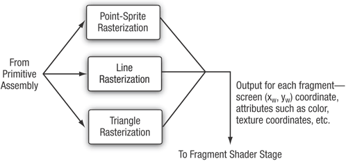
The next stage, shown in Figure 1-3, is the rasterization phase where the appropriate primitive (point-sprite, line, or triangle) is drawn. Rasterization is the process that converts primitives into a set of two-dimensional fragments, which are processed by the fragment shader. These two-dimensional fragments represent pixels that can be drawn on the screen.
The fragment shader implements a general-purpose programmable method for operating on fragments.
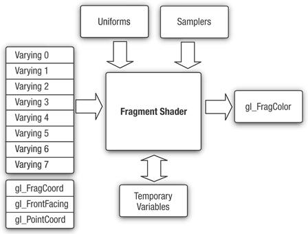
The fragment shader, as shown in Figure 1-4, is executed for each generated fragment by the rasterization stage and takes the following inputs:
Varying variables—Outputs of the vertex shader that are generated by the rasterization unit for each fragment using interpolation.
Uniforms—Constant data used by the fragment shader.
Samplers—A specific type of uniforms that represent textures used by the fragment shader.
Shader program—Fragment shader program source code or executable that describes the operations that will be performed on the fragment.
The fragment shader can either discard the fragment or generate a color value referred to as gl_FragColor. The color, depth, stencil, and screen coordinate location (xw, yw) generated by the rasterization stage become inputs to the per-fragment operations stage of the OpenGL ES 2.0 pipeline.
Example 1-2 describes a very simple fragment shader that can be coupled with the vertex shader described in Example 1-1 to draw a gouraud shaded triangle. Again, we will go into much more detail on fragment shaders later in the book. We present this just to give you a basic idea of what a fragment shader looks like.
Line 1 sets the default precision qualifier, which is explained in detail in Chapter 4, “Shaders and Programs.” Line 3 describes the input to the fragment shader. The vertex shader must write the same set of varying variables that are read by the fragment shader. Lines 6-10 describe the fragment shader main function. Note that no output is declared in the fragment shader. This is because the only output variable is gl_FragColor, which in this example is set to input color to the fragment shader given by v_color in line 9.
After the fragment shader, the next stage is per-fragment operations. A fragment produced by rasterization with (xw, yw) screen coordinates can only modify the pixel at location (xw, yw) in the framebuffer. Figure 1-5 describes the OpenGL ES 2.0 per-fragment operations stage.
The per-fragment operations stage performs the following functions (and tests) on each fragment, as shown in Figure 1-5:
Pixel ownership test—This test determines if the pixel at location (
xw,yw) in the framebuffer is currently owned by OpenGL ES. This test allows the window system to control which pixels in the framebuffer belong to the current OpenGL ES context. For example, if a window displaying the OpenGL ES framebuffer window is obscured by another window, the windowing system may determine that the obscured pixels are not owned by the OpenGL ES context and therefore might not be displayed at all.Scissor test—The scissor test determines if (
xw,yw) lies within the scissor rectangle defined as part of the OpenGL ES state. If the fragment is outside the scissor region, the fragment is discarded.Stencil and depth tests—These perform tests on the stencil and depth value of the incoming fragment to determine if the fragment should be rejected or not.
Blending—Blending combines the newly generated fragment color value with the color values stored in the framebuffer at location (
xw,yw).Dithering—Dithering can be used to minimize the artifacts that can occur from using limited precision to store color values in the framebuffer.
At the end of the per-fragment stage, either the fragment is rejected or a fragment color, depth, or stencil value is written to the framebuffer at location (xw, yw). The fragment color, depth, and stencil values are written depending on whether the appropriate write masks are enabled or not. Write masks allow finer control over the color, depth, and stencil values written into the appropriate buffers. For example, the write mask for the color buffer could be set such that no red values get written into the color buffer.
In addition, OpenGL ES 2.0 also provides an interface to read back the pixels from the framebuffer. Note that only pixels can be read back from the color buffer. The depth and stencil values cannot be read back.
Note
Alpha test and LogicOp are no longer part of the per-fragment operations stage. These two stages exist in OpenGL 2.0 and OpenGL ES 1.x. The alpha test stage is no longer needed because the fragment shader can discard fragments and therefore the alpha test can be performed in the fragment shader. In addition, LogicOp is removed as it is very infrequently used by applications and the OpenGL ES working group did not get requests from independent software vendors (ISVs) to support this feature in OpenGL ES 2.0.
OpenGL ES 2.0 is not backward compatible with OpenGL ES 1.x. It does not support the fixed function pipeline that OpenGL ES 1.x supports. The OpenGL ES 2.0 programmable vertex shader replaces the fixed function vertex units implemented in OpenGL ES 1.x. The fixed function vertex units implement a specific vertex transformation and lighting equation that can be used to transform the vertex position, transform or generate texture coordinates, and calculate the vertex color. Similarly, the programmable fragment shader replaces the fixed function texture combine units implemented in OpenGL ES 1.x. The fixed function texture combine units implement a texture combine stage for each texture unit. The texture color is combined with the diffuse color and the output of previous texture combine stage with a fixed set of operations such as add, modulate, subtract, and dot.
This is a departure from OpenGL 2.0, which implements a programmable pipeline but also provides full backward compatibility to older versions of OpenGL that implement a fixed function pipeline.
The OpenGL ES working group decided against backward compatibility for the following reasons:
Supporting the fixed function pipeline in OpenGL ES 2.0 implies that the API would support more than one way of implementing a feature, in violation of one of the criteria used by the working group in determining what features should be supported. The programmable pipeline allows applications to implement the fixed function pipeline using shaders, so there is really no compelling reason to be backward compatible with OpenGL ES 1.x.
Feedback from ISVs was that most games do not mix programmable and fixed function pipelines. They are either written for a fixed function pipeline or for a programmable pipeline. Once you have a programmable pipeline, there is no reason to use a fixed function pipeline as you have a lot more flexibility in the effects you want to render.
The OpenGL ES 2.0 driver’s memory footprint would be much larger if it had to support both the fixed function and programmable pipelines. For the devices targeted by OpenGL ES, minimizing memory footprint is an important design criteria. By separating the fixed function support into the OpenGL ES 1.x API and placing the programmable shader support into the OpenGL ES 2.0 API, vendors that do not require OpenGL ES 1.x support no longer need to include this driver at all.
Also note, unlike OpenGL ES 1.x, there are no profiles or “mandatory extensions” for OpenGL ES 2.0.
OpenGL ES commands require a rendering context and a drawing surface. The rendering context stores the appropriate OpenGL ES state. The drawing surface is the surface to which primitives will be drawn. The drawing surface specifies the types of buffers that are required for rendering such as a color buffer, depth buffer, and stencil buffer. The drawing surface also specifies the bit depths of each of the required buffers.
The OpenGL ES API does not mention how a rendering context is created or how the rendering context gets attached to the native windowing system. EGL is one interface between the Khronos rendering APIs such as OpenGL ES and the native window system. There is no requirement to provide EGL when implementing OpenGL ES. Developers should refer to the platform vendor’s documentation to determine which interface is supported.
Any OpenGL ES application will need to do the following using EGL before any rendering can begin:
Query the displays that are available on the device and initialize them. For example, a flip phone might have two LCD panels and it is possible that we can render using OpenGL ES to surfaces that can be displayed on either or both panels.
Create a rendering surface. Surfaces created in EGL can be categorized as on-screen surfaces or off-screen surfaces. On-screen surfaces are attached to the native window system, whereas off-screen surfaces are pixel buffers that do not get displayed but can be used as rendering surfaces. These surfaces can be used to render into a texture and can be shared across multiple Khronos APIs.
Create a rendering context. EGL is needed to create an OpenGL ES rendering context. This context needs to be attached to an appropriate surface before rendering can actually begin.
The EGL API implements the features just described and additional functionality such as power management, support for multiple rendering contexts in a process, sharing objects (such as textures or vertex buffers) across rendering contexts in a process, and a mechanism to get function pointers to EGL or OpenGL ES extension functions supported by a given implementation.
The latest version of the EGL specification is EGL version 1.4.
To write any OpenGL ES 2.0 application, you will need to know which header files need to be included and with which libraries your application needs to link. It is also useful to understand the syntax used by the EGL and GL command names and command parameters.
OpenGL ES 2.0 applications will need to link with the following libraries: the OpenGL ES 2.0 library named libGLESv2.lib and the EGL library named libEGL.lib.
OpenGL ES 2.0 applications will need to include the appropriate ES 2.0 and EGL header files. The following include files must be included by any OpenGL ES 2.0 application:
#include <EGL/egl.h>
#include <GLES2/gl2.h>
#include <GLES2/gl2ext.h>
egl.h is the EGL header file, gl2.h is the OpenGL ES 2.0 header file, and gl2ext.h is the header file that describes the list of Khronos-approved extensions for OpenGL ES 2.0.
The header file and library names are platform dependent. The OpenGL ES working group has tried to define the library and header names and how they should be organized but this might not be the case for all OpenGL ES platforms. Developers should, however, refer to the platform vendor’s documentation for information on how the libraries and include files are named and organized.
All EGL commands begin with the prefix egl and use an initial capital letter for each word making up the command name (e.g., eglCreateWindowSurface). Similarly, EGL data types also begin with the prefix EGL and use an initial capital letter for each word making up the type name except for EGLint and EGLenum.
Table 1-1 gives a brief description of EGL data types used.
All OpenGL ES commands begin with the prefix gl and use an initial capital letter for each word making up the command name (e.g., glBlendEquation). Similarly, OpenGL ES data types also begin with the prefix GL.
In addition, some commands might take arguments in different flavors. The flavors or types vary by the number of arguments taken (one to four arguments), the data type of the arguments used (byte [b], unsigned byte [ub], short [s], unsigned short [us], int [i], fixed [x], and float [f]), and whether the arguments are passed as a vector (v) or not. A few examples of command flavors allowed in OpenGL ES follow.
The following two commands are equivalent except one specifies the uniform value as floats and the other as integers.
glUniform2f(location, 1.0f, 0.0f);
glUniform2i(location, 1, 0)
The following lines describe commands that are also equivalent but one passes command arguments as a vector and the other does not.
GLfloat   coord[4] = { 1.0f, 0.75f, 0.25f, 0.0f };
glUniform4fv(location, coord);
glUniform4f(location, coord[0], coord[1], coord[2], coord[3]);
Table 1-2 gives a description of the command suffixes and argument data types used in OpenGL ES.
Table 1-2. OpenGL ES Command Suffixes and Argument Data Types
Data Type | Data Type | C-Language Type | GL Type |
|---|---|---|---|
| 8-bit signed integer |
|
|
| 8-bit unsigned integer |
|
|
| 16-bit signed integer |
|
|
| 16-bit unsigned integer |
|
|
| 32-bit signed integer |
|
|
| 32-bit unsigned integer |
|
|
| 16.16 fixed point |
|
|
| 32-bit floating point |
|
|
Finally, OpenGL ES defines the type GLvoid. This is used for OpenGL ES commands that accept pointers.
In the rest of this book, OpenGL ES commands are referred to by their base names only and an asterisk is used to indicate that this refers to multiple flavors of the command name. For example, glUniform*() stands for all variations of the command you use to specify uniforms and glUniform*v() refers to all the vector versions of the command you use to specify uniforms. If a particular version of a command needs to be discussed, we use the full command name with the appropriate suffixes.
OpenGL ES commands incorrectly used by applications generate an error code. This error code is recorded and can be queried using glGetError. No other errors will be recorded until the application has queried the first error code using glGetError. Once the error code has been queried, the current error code is reset to GL_NO_ERROR. The command that generated the error is ignored and does not affect the OpenGL ES state except for the GL_OUT_OF_MEMORY error described later in this section.
The glGetError command is described next.
|
|
Returns the current error code and resets the current error code to | |
Table 1-3 lists the basic error codes and their description. There are other error codes besides the basic error codes listed in Table 1-3 that are described in the chapters that cover OpenGL ES commands that generate these specific errors.
Table 1-3. OpenGL ES Basic Error Codes
Error Code | Description |
|---|---|
| No error has been generated since the last call to |
| A |
| A numeric argument is out of range. The command that generated the error is ignored. |
| The specific command cannot be performed in the current OpenGL ES state. The command that generated the error is ignored. |
| There is insufficient memory to execute this command. The state of the OpenGL ES pipeline is considered to be undefined if this error is encountered except for the current error code. |
The OpenGL ES 2.0 API inherits the OpenGL client-server model. The application, or client, issues commands, and these commands are processed by the OpenGL ES implementation or server. In OpenGL, the client and server can reside on different machines over a network. OpenGL ES also allows the client and server to reside on different machines but because OpenGL ES targets handheld and embedded platforms, the client and server will typically be on the same device.
In the client-server model, the commands issued by the client do not necessarily get sent to the server immediately. If the client and server are over a network, it will be very inefficient to send individual commands over the network. Instead, the commands can be buffered on the client side and then issued to the server at a later point in time. As a result, there needs to be a mechanism that lets the client know when the server has completed execution of previously submitted commands. Consider another example where multiple OpenGL ES contexts (each current to a different thread) are sharing objects. To synchronize correctly between these contexts, it is important that commands from context A be issued to the server before context B that depends on OpenGL ES state modified by context A. The glFlush command is used to flush any pending commands in the current OpenGL ES context and issue them to the server. Note that glFlush only issues the commands to the server and does not wait for them to complete. If the client requires that the commands be completed, the glFinish command should be used. We, however, do not recommend using glFinish unless absolutely necessary. Because glFinish does not return until all queued commands in the context have been completely processed by the server, calling glFinish can adversely impact performance by forcing the client and server to synchronize their operations.
void  glFlush(void)
void  glFinish(void)
Figure 1-1 showed the various pipeline stages in OpenGL ES 2.0. Each pipeline stage has state that can be enabled or disabled and appropriate state values that are maintained per context. Examples of state are blending enable, blend factors, cull enable, and cull face. This state is initialized with default values when an OpenGL ES context (EGLcontext) is initialized. The state enables can be set using the glEnable and glDisable commands.
|
|
|
|
| |
The chapters that follow will describe the specific state enables for each pipeline stage shown in Figure 1-1. You can also check if a state is currently enabled or disabled by using the glIsEnabled command.
|
|
Returns | |
Specific state values such as blend factor, depth test values, and so on can also be queried using appropriate glGet*** commands. These commands are described in detail in Chapter 14, “State Queries.”
The OpenGL ES 1.0, 1.1, and 2.0 specifications can be found at www.khronos.org/opengles/. In addition, the Khronos Web site (www.khronos.org) has the latest information on all Khronos specifications, developer message boards, tutorials, and examples.
Khronos OpenGL ES 1.1 Web site: www.khronos.org/opengles/1_X/
Khronos OpenGL ES 2.0 Web site: www.khronos.org/opengles/2_X/
Khronos EGL Web site: www.khronos.org/egl/
