
Now that we have covered vertex shaders in detail, you should be familiar with all of the gritty details in transforming vertices and preparing primitives for rendering. The next step in the pipeline is the fragment shader, where much of the visual magic of OpenGL ES 2.0 occurs. Programmable fragment shaders are fundamental in producing effects that include texturing, per-pixel lighting, and shadows. A fundamental aspect of fragment shaders is the application of textures to surfaces. This chapter covers all of the details of creating, loading, and applying textures:
Texturing basics.
Loading textures and mipmapping.
Texture filtering and wrapping.
Using textures in the fragment shader.
Texture subimage specification.
Copying texture data from the color buffer.
Optional texturing extensions.
One of the most fundamental operations used in rendering 3D graphics is the application of textures to a surface. Textures allow for the representation of additional detail not available just from the geometry of a mesh. Textures in OpenGL ES 2.0 come in two forms: 2D textures and cube map textures.
Textures are typically applied to a surface by using texture coordinates that can be thought of as indices into texture array data. The following sections introduce the different texture types in OpenGL ES and how they are loaded and accessed.
A 2D texture is the most basic and common form of texture in OpenGL ES. A 2D texture is—as you might guess—a two-dimensional array of image data. The individual data elements of a texture are known as texels. A texel is a shortened way of describing a texture pixel. Texture image data in OpenGL ES can be represented in many different basic formats. The basic formats available for texture data are shown in Table 9-1.
Each texel in the image is specified according to its basic format and also its data type. Later, we describe in more detail the various data types that can represent a texel. For now, the important point to understand is that a 2D texture is a two-dimensional array of image data. When rendering with a 2D texture, a texture coordinate is used as an index into the texture image. Generally, a mesh will be authored in a 3D content authoring program with each vertex having a texture coordinate. Texture coordinates for 2D textures are given by a 2D pair of coordinates (s, t), sometimes also called (u, v) coordinates. These coordinates represent normalized coordinates used to look up into a texture map as shown in Figure 9-1.

The lower left corner of the texture image is specified by the st-coordinates (0.0, 0.0). The upper right corner of the texture image is specified by the st-coordinates (1.0, 1.0). Coordinates outside of the range [0.0, 1.0] are allowed, and the behavior of texture fetches outside of that range is defined by the texture wrapping mode (described in the section on texture filtering and wrapping).
In addition to 2D textures, OpenGL ES 2.0 also supports cubemap textures. At its most basic, a cubemap is a texture made up of six individual 2D texture faces. Each face of the cubemap represents one of the six sides of a cube. Cubemaps have a variety of advanced uses in 3D rendering, but the most basic use is for an effect known as environment mapping. For this effect, the reflection of the environment onto the object is rendered by using a cubemap to represent the environment. The typical way that a cubemap is generated for environment mapping is that a camera is placed in the center of the scene and an image of the scene is captured from each of the six axis directions (+X, -X, +Y, -Y, +Z, -Z) and stored in each cube face.
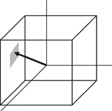
The way that texels are fetched out of a cubemap is by using a 3D vector (s,t,r) as the texture coordinate to look up into a cubemap. The 3D vector is used to first select a face of the cubemap to fetch from, and then the coordinate is projected into a 2D (s,t) coordinate to fetch from the cubemap face. The actual math for computing the 2D (s,t) coordinate is outside our scope here, but suffice to say that a 3D vector is used to look up into a cubemap. You can visualize the way this works by picturing a 3D vector coming from the origin inside of a cube. The point at which that vector intersects the cube is the texel that would be fetched from the cubemap. This is shown in Figure 9-2, where a 3D vector intersects the cube face.
The faces of a cubemap are each specified in the same manner as one would specify a 2D texture. Each of the faces must be square (e.g., the width and height must be equal) and each of the faces must have the same width and height. The 3D vector that is used for the texture coordinate is not normally stored directly per-vertex on the mesh as it is for 2D texturing. Rather, the most common way cubemaps are fetched from is to use the normal vector as a basis for computing the cubemap texture coordinate. Typically the normal vector is used along with a vector from the eye to compute a reflection vector that is then used to look up into a cubemap. This computation is described in the environment mapping example in Chapter 13, “Advanced Programming with OpenGL ES 2.0.”
The first step in the application of textures is to create a texture object. A texture object is a container object that holds the texture data that is needed for rendering such as image data, filtering modes, and wrap modes. In OpenGL ES, a texture object is represented by an unsigned integer that is a handle to the texture object. The function that is used for generating texture objects is glGenTextures.
|
|
| specifies the number of texture objects to generate |
| an array of unsigned integers that will hold |
Texture objects also need to be deleted when an application no longer needs them. This is typically either done at application shutdown or, for example, when changing levels in a game. This can be done using glDeleteTextures.
|
|
| specifies the number of texture objects to delete |
| an array of unsigned integers that hold |
Once texture object IDs have been generated with glGenTextures, the application must bind the texture object to operate on it. Once texture objects are bound, subsequent operations such as glTexImage2D and glTexParameter affect the bound texture object. The function used to bind texture objects is glBindTexture.
|
|
| bind the texture object to target |
| the handle to the texture object to bind |
Once a texture is bound to a particular texture target, that texture object will remain bound to that target until it is deleted. After generating a texture object and binding it, the next step to using a texture is to actually load the image data. The primary function that is used for loading textures is glTexImage2D.
|
|
specifies the texture target, either | |
| specifies which mip level to load. The base level is specified by 0 followed by an increasing level for each successive mipmap |
| the internal format for the texture storage, can be:
|
| the width of the image in pixels |
| the height of the image in pixels |
| this parameter is ignored in OpenGL ES, but it was kept for compatibility with the desktop OpenGL interface; should be 0 |
| the format of the incoming texture data. Note that in OpenGL ES the |
| the type of the incoming pixel data, can be:
|
| contains the actual pixel data for the image. The data must contain ( |
The code in Example 9-1 from the Simple_Texture2D example demonstrates generating a texture object, binding it, and then loading a 2 × 2 2D texture with RGB image data made from unsigned bytes.
Example 9-1. Generating a Texture Object, Binding It, and Loading Image Data
// Texture object handle
GLuint textureId;

// 2 x 2 Image, 3 bytes per pixel(R, G, B)
GLubyte pixels[4 * 3] =
{
   255,   0,   0, // Red
     0, 255,   0, // Green
     0,   0, 255, // Blue
   255, 255,   0  // Yellow
};

// Use tightly packed data
glPixelStorei(GL_UNPACK_ALIGNMENT, 1);

// Generate a texture object
glGenTextures(1, &textureId);

// Bind the texture object
glBindTexture(GL_TEXTURE_2D, textureId);

// Load the texture
glTexImage2D(GL_TEXTURE_2D, 0, GL_RGB, 2, 2, 0, GL_RGB,
             GL_UNSIGNED_BYTE, pixels);

// Set the filtering mode
glTexParameteri(GL_TEXTURE_2D, GL_TEXTURE_MIN_FILTER, GL_NEAREST);
glTexParameteri(GL_TEXTURE_2D, GL_TEXTURE_MAG_FILTER, GL_NEAREST);
In the first part of the code, the pixels array is initialized with simple 2 × 2 texture data. The data is composed of unsigned byte RGB triplets that are in the range [0, 255]. When data is fetched from an 8-bit unsigned byte texture component in the shader, the values are mapped from the range [0, 255] to the floating-point range [0.0, 1.0]. Typically, an application would not create texture data in this simple manner but rather load the data from an image file. This example is provided to demonstrate the use of the API.
Note that prior to calling glTexImage2D the application makes a call to glPixelStorei to set the unpack alignment. When texture data is uploaded via glTexImage2D, the rows of pixels are assumed to be aligned to the value set for GL_UNPACK_ALIGNMENT. By default, the value is 4, meaning that rows of pixels are assumed to begin on 4-byte boundaries. This application sets the unpack alignment to 1, meaning that each row of pixels begins on a byte boundary (in other words, the data is tightly packed). The full definition for glPixelStorei is given next.
|
|
| specifies the pixel storage type to set, must be either |
| specifies the integer value for the pack or unpack alignment |
The GL_PACK_ALIGNMENT argument to glPixelStorei does not have any impact on texture image uploading. The pack alignment is used by glReadPixels, which is described in Chapter 11, “Fragment Operations.” The pack and unpack alignments set by glPixelStorei are global state and are not stored or associated with a texture object.
Back to the example program, after defining the image data, a texture object is generated using glGenTextures and then that object is bound to the GL_TEXTURE_2D target using glBindTexture. Finally, the image data is loaded into the texture object using glTexImage2D. The format is set as GL_RGB, which signifies that the image data is composed of (R,G,B) triplets. The type is set as GL_UNSIGNED_BYTE, which signifies that each channel of the data is stored in an 8-bit unsigned byte. There are a number of other options for loading texture data, including different formats as described in Table 9-1. In addition, all of the components in a texel can be packed into 16 bits using GL_UNSIGNED_SHORT_4_4_4_4, GL_UNSIGNED_SHORT_5_5_5_1, or GL_UNSIGNED_SHORT_5_6_5.
The last part of the code uses glTexParameteri to set the minification and magnification filtering modes to GL_NEAREST. This code is required because we have not loaded a complete mipmap chain for the texture so we must select a nonmipmapped minification filter. The other option would have been to use minification and magnification modes of GL_LINEAR, which provides bilinear nonmipmapped filtering. The details of texture filtering and mipmapping are explained in the next section.
So far, we have limited our explanation of 2D textures to describing a single 2D image. Although this allowed us to explain the concept of texturing, there is actually a bit more to how textures are specified and used in OpenGL ES. The reason has to do with the visual artifacts and performance issues that occur due to using a single texture map. As we have described texturing so far, the texture coordinate is used to generate a 2D index to fetch from the texture map. When the minification and magnification filters are set to GL_NEAREST, this is exactly what will happen: a single texel will be fetched at the texture coordinate location provided. This is known as point or nearest sampling.
However, nearest sampling might produce significant visual artifacts. The reason for the artifacts is that as a triangle becomes smaller in screen space, the texture coordinates take large jumps when being interpolated from pixel to pixel. As a result, a small number of samples are taken from a large texture map, resulting in aliasing artifacts. The solution that is used to resolve this type of artifact in OpenGL ES is known as mipmapping. The idea behind mipmapping is to build a chain of images known as a mipmap chain. The mipmap chain begins with the originally specified image and then continues with each subsequent image being half as large in each dimension as the one before it. This chain continues until we reach a single 1 × 1 texture at the bottom of the chain. The mip levels can be generated programmatically, typically by computing each pixel in a mip level as an average of the four pixels at the same location in the mip level above it (box filtering).
In the Chapter_9/MipMap2D sample program, we provide an example demonstrating how to generate a mipmap chain for a texture using a box filtering technique. The code to generate the mipmap chain is given by the GenMipMap2D function. This function takes an RGB8 image as input and generates the next mipmap level by performing a box filter on the preceding image. Please see the source code in the example for details on how the box filtering is done. The mipmap chain is then loaded using glTexImage2D as shown in Example 9-2.
Example 9-2. Loading a 2D Mipmap Chain
// Load mipmap level 0
glTexImage2D(GL_TEXTURE_2D, 0, GL_RGB, width, height,
             0, GL_RGB, GL_UNSIGNED_BYTE, pixels);

level = 1;
prevImage = &pixels[0];

while(width > 1 && height > 1)
{
   int newWidth,
       newHeight;
   // Generate the next mipmap level
   GenMipMap2D(prevImage, &newImage, width, height,
               &newWidth, &newHeight);

   // Load the mipmap level
   glTexImage2D(GL_TEXTURE_2D, level, GL_RGB,
                newWidth, newHeight, 0, GL_RGB,
                GL_UNSIGNED_BYTE, newImage);

   // Free the previous image
   free(prevImage);

   // Set the previous image for the next iteration
   prevImage = newImage;
   level++;

   // Half the width and height
   width = newWidth;
   height = newHeight;

}

free(newImage);
With a mipmap chain loaded, we can then set up the filtering mode to use mipmaps. The result is that we achieve a better ratio between screen pixels and texture pixels and thereby reduce aliasing artifacts. Aliasing is also reduced because each image in the mipmap chain is successively filtered so that high-frequency elements are attenuated further and further as we move down the chain.
There are two different types of filtering that occur when texturing: minification and magnification. Minification is what happens when the size of the projected polygon on the screen is smaller than the size of the texture. Magnification is what happens when the size of the projected polygon on screen is larger than the size of the texture. The determination of which filter type to use is all done automatically by the hardware, but the API provides control over what type of filtering to use in each case. For magnification, mipmapping is not relevant, because we will always be sampling from the largest level available. For minification, there are a variety of different sampling modes that can be used. The choice of which mode to use is based on the visual quality you need to achieve and how much performance you are willing to give up for texture filtering.
The way that the filtering modes are specified is with glTexParameter[i|f][v].
| |
|
|
|
|
|
|
| bind the texture object to target |
| the parameter to set, one of:
|
| the value (or array of values for the “v” entrypoints) to set the texture parameter to |
If
| |
If
| |
If
|
The magnification filter can be either GL_NEAREST or GL_LINEAR. In GL_NEAREST magnification filtering, a single point sample will be taken from the texture nearest to the texture coordinate. In GL_LINEAR magnification filtering, a bilinear (average of four samples) will be taken from the texture about the texture coordinate.
The minification filter can be set to any of the following values:
GL_NEAREST—. A single point sample will be taken from the texture nearest to the texture coordinate.GL_LINEAR—. A bilinear sample will be taken from the texture nearest to the texture coordinate.GL_NEAREST_MIPMAP_NEAREST—. A single point sample will be taken from the closest mip level chosen.GL_NEAREST_MIPMAP_LINEAR—. Will take a sample from the two closest mip levels and interpolate between those samples.GL_LINEAR_MIPMAP_NEAREST—. Will take a bilinear fetch from the closest mip level chosen.GL_LINEAR_MIPMAP_LINEAR—. Will take a bilinear fetch from each of the two closest mip levels and then interpolate between them. This last mode is typically referred to as trilinear filtering and produces the best quality of all modes.
Note
GL_NEAREST and GL_LINEAR are the only texture minification modes that do not require a complete mipmap chain to be specified for the texture. All of the other modes require that a complete mipmap chain exists for the texture.
The MipMap2D example in Figure 9-3 shows the difference between a polygon drawn with GL_NEAREST versus GL_LINEAR_MIPMAP_LINEAR filtering.
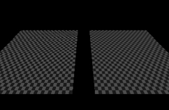
It is worth mentioning some performance implications for the texture filtering mode that you choose. If minification occurs and performance is a concern, using a mipmap filtering mode is usually the best choice on most hardware. The reason is because you tend to get very poor texture cache utilization without mipmaps because fetches happen at sparse locations throughout a map. However, the higher the filtering mode you use, there usually is some performance cost in the hardware. For example, on most hardware it is the case that doing bilinear filtering is less costly than doing trilinear filtering. You should choose a mode that gives you the quality desired without unduly negatively impacting performance. On some hardware, you might get high-quality filtering virtually for free particularly if the cost of the texture filtering is not your bottleneck. This is something that needs to be tuned for the application and hardware on which you plan to run your application.
In the MipMap2D example in the previous section, the application created an image for level zero of the mipmap chain. It then generated the rest of the mipmap chain by performing a box filter on each image and successively halving the width and height. This is one way to generate mipmaps, but OpenGL ES 2.0 also provides a mechanism for automatically generating mipmaps using glGenerateMipmap.
|
|
| the texture target to generate mipmaps for, can be |
When calling glGenerateMipmap on a bound texture object, this function will generate the entire mipmap chain from the contents of the image in level zero. For a 2D texture, this means that the contents of texture level zero will be successively filtered and used for each of the subsequent levels. For a cubemap, each of the cube faces will be generated from the level zero in each cube face. Note that to use this function with cubemaps you must have specified level zero for each cube face and each face must have a matching internal format, width, and height. An additional note is that OpenGL ES 2.0 does not mandate a particular filtering algorithm that will be used for generating mipmaps (although it recommends box filtering). If you require a particular filtering method, then you will still need to generate the mipmaps on your own.
Automatic mipmap generation becomes particularly important when you start to use framebuffer objects for rendering to a texture. When rendering to a texture, we don’t want to have to read back the contents of the texture to the CPU to generate mipmaps. Instead, glGenerateMipmap can be used and the graphics hardware can then potentially generate the mipmaps without ever having to read the data back to the CPU. When we cover framebuffer objects in more detail in Chapter 12, “Framebuffer Objects,” this point should become clear.
Texture wrap modes are used to set what the behavior is when a texture coordinate is outside of the range [0.0, 1.0]. The texture wrap modes are set using glTexParameter[i|f][v]. The texture wrap mode can be set independently for both the s-coordinate and t-coordinate. The GL_TEXTURE_WRAP_S mode defines what the behavior is when the s-coordinate is outside of the range [0.0, 1.0] and GL_TEXTURE_WRAP_T sets the behavior for the t-coordinate. In OpenGL ES, there are three wrap modes to choose from, as described in Table 9-2.
Note that the texture wrap modes also have an impact for the behavior of filtering. For example, when a texture coordinate is at the edge of a texture, the bilinear filter kernel might span beyond the edge of the texture. In this case, the wrap mode will determine which texels are fetched for the portion of the kernel that is outside the texture edge. GL_CLAMP_TO_EDGE should be used whenever you do not want any form of repeating.
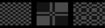
In Chapter_9/TextureWrap there is an example that draws a quad with each of the three different texture wrap modes. The quads have a checkerboard image applied to them and are rendered with texture coordinates in the range from [–1.0, 2.0]. The results are shown in Figure 9-4.
The three quads are rendered using the following setup code for the texture wrap modes.
// Draw left quad with repeat wrap mode
glTexParameteri(GL_TEXTURE_2D, GL_TEXTURE_WRAP_S, GL_REPEAT);
glTexParameteri(GL_TEXTURE_2D, GL_TEXTURE_WRAP_T, GL_REPEAT);
glUniform1f(userData->offsetLoc, -0.7f);
glDrawElements(GL_TRIANGLES, 6, GL_UNSIGNED_SHORT, indices);

// Draw middle quad with clamp to edge wrap mode
glTexParameteri(GL_TEXTURE_2D, GL_TEXTURE_WRAP_S, GL_CLAMP_TO_EDGE);
glTexParameteri(GL_TEXTURE_2D, GL_TEXTURE_WRAP_T, GL_CLAMP_TO_EDGE);
glUniform1f(userData->offsetLoc, 0.0f);
glDrawElements(GL_TRIANGLES, 6, GL_UNSIGNED_SHORT, indices);

// Draw right quad with mirrored repeat
glTexParameteri(GL_TEXTURE_2D, GL_TEXTURE_WRAP_S,
                GL_MIRRORED_REPEAT);
glTexParameteri(GL_TEXTURE_2D, GL_TEXTURE_WRAP_T,
                GL_MIRRORED_REPEAT);
glUniform1f(userData->offsetLoc, 0.7f);
glDrawElements GL_TRIANGLES, 6, GL_UNSIGNED_SHORT, indices);
In Figure 9-4, the quad on the far left is rendered using GL_REPEAT mode. In this mode, the texture simply repeats outside of the range [0, 1] resulting in a tiling pattern of the image. The quad in the center is rendered with GL_CLAMP_TO_EDGE mode. As you can see, when the texture coordinates go outside the range [0, 1], the texture coordinates get clamped to sample from the edge of the texture. The quad on the right is rendered with GL_MIRRORED_REPEAT, which mirrors and then repeats the image when the texture coordinates are outside [0, 1].
Now that we have covered the basics of setting up texturing, let’s take a look at some sample shader code. The vertex-fragment shader pair in Example 9-3 from the Simple_Texture2D sample demonstrates the basics of how 2D texturing is done in a shader.
Example 9-3. Vertex and Fragment Shader for Performing 2D Texturing
GLbyte vShaderStr[] =
   "attribute vec4 a_position;
"
   "attribute vec2 a_texCoord;
"
   "varying vec2 v_texCoord;
"
   "void main()
"
   "{
"
   "   gl_Position = a_position;
"
   "   v_texCoord = a_texCoord;
"
   "}
";

GLbyte fShaderStr[] =
   "precision mediump float;
"
   "varying vec2 v_texCoord;
"
   "uniform sampler2D s_texture;
"
   "void main()
"
   "{
"
   "  gl_FragColor = texture2D(s_texture, v_texCoord);
"
   "}
";
The vertex shader takes in a two-component texture coordinate as a vertex attribute and passes it through as a varying to the fragment shader. The fragment shader consumes that varying and will use it as a texture coordinate for the texture fetch. The fragment shader declares a uniform variable of type sampler2D called s_texture. A sampler is a special type of uniform variable that is used to fetch from a texture map. The sampler uniform will be loaded with a value specifying the texture unit to which the texture is bound; for example, specifying that a sampler with a value of 0 says to fetch from unit GL_TEXTURE0, and a value of 1 from GL_TEXTURE1, and so on. The way that textures get bound to texture units is using the glActiveTexture function.
|
|
texture | the texture unit to make active, |
The function glActiveTexture sets the current texture unit so that subsequent calls to glBindTexture will bind the texture to the currently active unit. The number of texture units available on an implementation of OpenGL ES can be queried for by using glGetIntegeriv with the parameter GL_MAX_TEXTURE_IMAGE_UNITS.
The following example code from the Simple_Texture2D example shows how the sampler and texture gets bound to the texture unit.
// Get the sampler locations
userData->samplerLoc = glGetUniformLocation(
                              userData->programObject,
                              "s_texture");

// ...
// Bind the texture
glActiveTexture(GL_TEXTURE0);
glBindTexture(GL_TEXTURE_2D, userData->textureId);

// Set the sampler texture unit to 0
glUniform1i(userData->samplerLoc, 0);
So finally, we have the texture loaded, the texture bound to texture unit 0, and the sampler set to use texture unit 0. Going back to the fragment shader in the Simple_Texture2D example, we see that the shader code then uses the built-in function texture2D to fetch from the texture map. The texture2D built-in function takes the form shown here.
|
|
| a sampler bound to a texture unit specifying the texture from which to fetch |
| a 2D texture coordinate used to fetch from the texture map |
| an optional parameter that provides a mipmap bias used for the texture fetch. This allows the shader to explicitly bias the computed LOD value used for mipmap selection |
The texture2D returns a vec4 representing the color fetched from the texture map. The way the texture data is mapped into the channels of this color is dependent on the base format of the texture. Table 9-3 shows the way in which texture formats are mapped to vec4 colors.
In the case of the Simple_Texture2D example, the texture was loaded as GL_RGB so the result of the texture fetch will be a vec4 with values (R, G, B, 1.0).
Using a cubemap texture is very similar to using a 2D texture. The example Simple_TextureCubemap demonstrates drawing a sphere with a simple cubemap. The cubemap contains six 1 × 1 faces, each with a different color. The code in Example 9-4 is used to load the cubemap texture.
Example 9-4. Loading a Cubemap Texture
GLuint CreateSimpleTextureCubemap()
{
   GLuint textureId;
   // Six 1 x 1 RGB faces
   GLubyte cubePixels[6][3] =
   {
      // Face 0 - Red
      255, 0, 0,
      // Face 1 - Green,
      0, 255, 0,
      // Face 3 - Blue
      0, 0, 255,
      // Face 4 - Yellow
      255, 255, 0,
      // Face 5 - Purple
      255, 0, 255,
      // Face 6 - White
      255, 255, 255
   };
   // Generate a texture object
   glGenTextures(1, &textureId);

   // Bind the texture object
   glBindTexture(GL_TEXTURE_CUBE_MAP, textureId);

   // Load the cube face - Positive X
   glTexImage2D(GL_TEXTURE_CUBE_MAP_POSITIVE_X, 0, GL_RGB, 1, 1,
                0, GL_RGB, GL_UNSIGNED_BYTE, &cubePixels[0]);

   // Load the cube face - Negative X
   glTexImage2D(GL_TEXTURE_CUBE_MAP_NEGATIVE_X, 0, GL_RGB, 1, 1,
                0, GL_RGB, GL_UNSIGNED_BYTE, &cubePixels[1]);

   // Load the cube face - Positive Y
   glTexImage2D(GL_TEXTURE_CUBE_MAP_POSITIVE_Y, 0, GL_RGB, 1, 1,
                0, GL_RGB, GL_UNSIGNED_BYTE, &cubePixels[2]);

   // Load the cube face - Negative Y
   glTexImage2D(GL_TEXTURE_CUBE_MAP_NEGATIVE_Y, 0, GL_RGB, 1, 1,
                0, GL_RGB, GL_UNSIGNED_BYTE, &cubePixels[3]);

   // Load the cube face - Positive Z
   glTexImage2D(GL_TEXTURE_CUBE_MAP_POSITIVE_Z, 0, GL_RGB, 1, 1,
                0, GL_RGB, GL_UNSIGNED_BYTE, &cubePixels[4]);

   // Load the cube face - Negative Z
   glTexImage2D(GL_TEXTURE_CUBE_MAP_NEGATIVE_Z, 0, GL_RGB, 1, 1,
                0, GL_RGB, GL_UNSIGNED_BYTE, &cubePixels[5]);

   // Set the filtering mode
   glTexParameteri(GL_TEXTURE_CUBE_MAP, GL_TEXTURE_MIN_FILTER,
                   GL_NEAREST);
   glTexParameteri(GL_TEXTURE_CUBE_MAP, GL_TEXTURE_MAG_FILTER,
                   GL_NEAREST);

   return textureId;

}
This code loads each individual cubemap face with 1 × 1 RGB pixel data by calling glTexImage2D for each cubemap face. The shader code to render the sphere with a cubemap is provided in Example 9-5.
Example 9-5. Vertex and Fragment Shader Pair for Cubemap Texturing
GLbyte vShaderStr[] =
   "attribute vec4 a_position;
"
   "attribute vec3 a_normal;
"
   "varying vec3 v_normal;
"
   "void main()
"
   "{
"
   "   gl_Position = a_position;
"
   "   v_normal = a_normal;
"
   "}
";

GLbyte fShaderStr[] =
   "precision mediump float;
"
   "varying vec3 v_normal;
"
   "uniform samplerCube s_texture;
"
   "void main()
"
   "{
"
   "  gl_FragColor = textureCube(s_texture, v_normal);
"
   "}
";
The vertex shader takes in a position and normal as vertex attributes. A normal is stored at each vertex of the sphere that will be used as a texture coordinate. The normal is passed through to the fragment shader in a varying. The fragment shader then uses the built-in function textureCube to fetch from the cubemap using the normal as a texture coordinate. The textureCube built-in function takes the form shown here.
|
|
| the sampler is bound to a texture unit specifying the texture from which to fetch |
| a 3D texture coordinate used to fetch from the cubemap |
| an optional parameter that provides a mipmap bias used for the texture fetch. This allows the shader to explicitly bias the computed LOD value used for mipmap selection |
The function for fetching a cubemap is very similar to a 2D texture. The only difference is that the texture coordinate is three components instead of two and the sampler type must be samplerCube. The same method is used to bind the cubemap texture and load the sampler as is used for the Simple_Texture2D example.
Thus far, we have been dealing with textures that were loaded with uncompressed texture image data using glTexImage2D. OpenGL ES 2.0 also supports the loading of compressed texture image data. There are several reasons why compressing textures is desirable. The first and obvious reason to compress textures is to reduce the memory footprint of the textures on the device. A second, less obvious reason to compress textures is that there is a memory bandwidth savings when fetching from compressed textures in a shader. Finally, compressed textures might allow you to reduce the download size of your application by reducing the amount of image data that must be stored.
The core OpenGL ES 2.0 specification does not define any compressed texture image formats. That is, OpenGL ES 2.0 core simply defines a mechanism whereby compressed texture image data can be loaded, but no compressed formats are defined. It is up to the vendor that implements OpenGL ES 2.0 to provide optional extension(s) that provide compressed image data types. One ratified compressed texture extension, Ericsson Texture Compression (ETC), is likely to be supported by a number of vendors. Vendors such as AMD, ARM, Imagination Technologies, and NVIDIA also provide hardware-specific extensions for formats that their hardware supports.
The function used to load compressed image data for 2D textures and cubemaps is glCompressedTexImage2D.
|
|
| specifies the texture target, should be |
| specifies which mip level to load. The base level is specified by 0 followed by an increasing level for each successive mipmap |
the internal format for the texture storage. This is the compressed texture format to use. No compressed formats are defined by core OpenGL ES 2.0, so the format used here must come from an extension | |
| the width of the image in pixels |
| the height of the image in pixels |
| this parameter is ignored in OpenGL ES, it was kept for compatibility with the desktop OpenGL interface. Should be 0 |
| the size of the image in bytes |
| contains the actual compressed pixel data for the image. These data must hold imageSize number of bytes |
Once a texture has been loaded as a compressed texture, it can be used for texturing in exactly the same way as an uncompressed texture. Note that if you attempt to use a texture compression format on an OpenGL ES 2.0 implementation that does not support it, a GL_INVALID_ENUM error will be generated. It is important that you check that the OpenGL ES 2.0 implementation exports the extension string for the texture compression format you use. If it does not, you must fall back to using an uncompressed texture format.
In addition to checking extension strings, there is another method you can use to determine which texture compression formats are supported by an implementation. You can query for GL_NUM_COMPRESSED_TEXTURE_FORMATS using glGetIntegerv to determine the number of compressed image formats supported. You can then query for GL_COMPRESSED_TEXTURE_FORMATS using glGetIntegerv, which will return an array of GLenum values. Each GLenum value in the array will be a compressed texture format that is supported by the implementation.
After uploading a texture image using glTexImage2D, it is possible to update portions of the image. This would be useful if you wanted to update just a subregion of an image. The function to load a portion of a 2D texture image is glTexSubImage2D.
| |
| specifies the texture target, either |
| specifies which mip level to update |
| the x index of the texel to start updating from |
| the y index of the texel to start updating from |
| the width of the subregion of the image to update |
| the height of the subregion of the image to update |
| the format of the incoming texture data, can be:
|
| the type of the incoming pixel data, can be:
|
| contains the actual pixel data for the subregion of the image |
This function will update the region of texels in the range (xoffset, yoffset) to (xoffset + width - 1, yoffset + height - 1). Note that to use this function, the texture must already be fully specified. The range of the subimage must be within the bounds of the previously specified texture image. The data in the pixels array must be aligned to the alignment that is specified by GL_UNPACK_ALIGNMENT with glPixelStorei.
There is also a function for updating a subregion of a compressed 2D texture image that is glCompressedTexSubImage2D. The definition for this function is more or less the same as glTexImage2D.
| |
| specifies the texture target, either |
| specifies which mip level to update |
| the x index of the texel to start updating from |
| the y index of the texel to start updating from |
| the width of the subregion of the image to update |
| the height of the subregion of the image to update |
| the compressed texture format to use. No compressed formats are defined by core OpenGL ES 2.0, so the format used here must come from an extension and match the format with which the image was originally specified |
| contains the actual pixel data for the subregion of the image |
An additional texturing feature that is supported in OpenGL ES 2.0 is the ability to copy data from the color buffer to a texture. This can be useful if you want to use the results of rendering as an image in a texture. Please note that framebuffer objects (Chapter 12) provide a fast method for doing render-to-texture and are a faster method than copying image data. However, if performance is not a concern, the ability to copy image data out of the color buffer can be a useful feature.
Recall that OpenGL ES 2.0 only supports double-buffered EGL displayable surfaces. This means that all OpenGL ES 2.0 applications that draw to the display will have a color buffer for both the front and back buffer. The buffer that is currently front or back is determined by the most recent call to eglSwapBuffers (described in Chapter 3, “An Introduction to EGL”). When you copy image data out of the color buffer from a displayable EGL surface, you will always be copying the contents of the back buffer. If you are rendering to an EGL pbuffer, then copying will occur from the pbuffer surface. Finally, if you are rendering to a framebuffer object, then copying will occur out of the color buffer attached to the framebuffer object as the color attachment.
The functions to copy data from the color buffer to a texture are glCopyTexImage2D and glCopyTexSubImage2D.
|
|
| specifies the texture target, either |
| specifies which mip level to load |
| the internal format of the image, can be:
|
| the x window-coordinate of the lower left rectangle in the framebuffer to read from |
| the y window-coordinate of the lower left rectangle in the framebuffer to read from |
| the width in pixels of the region to read |
| the height in pixels of the region to read |
| borders are not supported in OpenGL ES 2.0, so this parameter must be 0 |
Calling this function will cause the texture image to be loaded with the pixels in the color buffer from region (x, y) to (x + width - 1, y + height - 1). This width and height of the texture image will be the size of the region copied from the color buffer. You should be using this to fill the entire contents of the texture.
In addition, you can update just the subregion of an already specified image using glCopyTexSubImage2D.
|
|
| specifies the texture target, either |
| specifies which mip level to update |
| the x index of the texel to start updating from |
| the y index of the texel to start updating from |
| the x window-coordinate of the lower left rectangle in the framebuffer to read from |
| the y window-coordinate of the lower left rectangle in the framebuffer to read from |
| the width in pixels of the region to read |
| the height in pixels of the region to read |
This function will update the subregion of the image starting at (xoffset, yoffset) to (xoffset + width – 1, yoffset + height – 1) with the pixels in the color buffer from (x, y) to (x + width – 1, y + height – 1).
One thing to keep in mind with both glCopyTexImage2D and glCopyTexSubImage2D is that the texture image format cannot have more components than the color buffer. In other words, when copying data out of the color buffer, it is possible to convert to a format with fewer components, but not with more. Table 9-4 shows the valid format conversions when doing a texture copy. For example, you can see from the table that it is possible to copy an RGBA image into any of the possible formats. However, it is not possible to copy an RGB into an RGBA image because no alpha component exists in the color buffer.
There are a number of Khronos-ratified extensions that provide additional texture functionality beyond what is available in core OpenGL ES 2.0. These extensions provide support for 3D textures, floating-point textures, Ericsson texture compression, and non-power-of-2 textures. The following sections contain descriptions of the Khronos-ratified texture extensions.
In addition to 2D textures and cubemaps, there is a ratified OpenGL ES 2.0 extension for 3D textures named GL_OES_texture_3D. This extension exposes methods for loading and rendering with 3D textures (or volume textures). 3D textures can be thought of as an array of multiple slices of 2D textures. A 3D texture is accessed with a three-tuple (s,t,r) coordinate much like a cubemap. For 3D textures, the r-coordinate selects which slice of the 3D texture to sample from and the (s,t) coordinate is used to fetch into the 2D map at each slice. Each mipmap level in a 3D texture contains half the number of slices in the texture above it.
The command to load 3D textures is glTexImage3DOES, which is very similar to glTexImage2D.
|
|
| specifies the texture target, should be |
| specifies which mip level to load. The base level is specified by 0 followed by an increasing level for each successive mipmap |
| the internal format for the texture storage, can be:
|
| the width of the image in pixels |
| the height of the image in pixels |
| the number of slices of the 3D texture |
| this parameter is ignored in OpenGL ES. It was kept for compatibility with the desktop OpenGL interface. Should be 0 |
| the format of the incoming texture data. Note that in OpenGL ES the |
| the type of the incoming pixel data, can be:
|
| contains the actual pixel data for the image. The data must contain ( |
Once a 3D texture has been loaded using glTexImage3DOES the texture can be fetched in the shader using the texture3D built-in function. Before doing so, the shader must enable the 3D texture extension using the #extension mechanism.
#extension GL_OES_texture_3D : enable
Once the extension is enabled in the fragment shader, the shader can use the texture3D built-in function, which takes the following form:
|
|
| a sampler bound to a texture unit specifying the texture to fetch from |
| a 3D texture coordinate used to fetch from the texture map |
| an optional parameter that provides a mipmap bias use for the texture fetch. This allows the shader to explicitly bias the computed LOD value used for mipmap selection |
Note that the r-coordinate is a floating point value. Depending on the filtering mode set, the texture fetch might span two slices of the volume. The 3D texture extension also adds support for GL_TEXTURE_WRAP_R_OES, which can be used to set the r-coordinate wrap mode (just like the s- and t-coordinate wrap modes for 2D textures). In addition, this extension adds support for loading compressed 3D texture data. Compressed 3D texture data can be loaded using the glCompressedTexImage3DOES function. As with compressed 2D textures, no specific compressed 3D texture formats are given by this extension.
|
|
specifies the texture target, should be | |
| specifies which mip level to load. The base level is specified by 0 followed by an increasing level for each successive mipmap |
| the internal format for the texture storage. This is the compressed texture format to use. No compressed formats are defined by OES_texture_3D, so the format used here must come from another extension |
| the width of the image in pixels |
| the height of the image in pixels |
| the depth of the image in pixels |
| this parameter is ignored in OpenGL ES. It was kept for compatibility with the desktop OpenGL interface. Should be 0 |
| the size of the image in bytes |
| contains the actual compressed pixel data for the image. These data must hold imageSize number of bytes |
In addition, just as with 2D textures, it is possible to update just a subregion of an existing 3D texture using glTexSubImage3DOES.
|
|
| specifies the texture target, either |
| specifies which mip level to update |
| the x index of the texel to start updating from |
the y index of the texel to start updating from | |
| the z index of the texel to start updating from |
| the width of the subregion of the image to update |
| the height of the subregion of the image to update |
| the depth of the subregion of the image to update |
| the format of the incoming texture data, can be: |
| |
| |
| |
| |
| |
| the type of the incoming pixel data, can be:
|
| contains the actual pixel data for the subregion of the image |
glTexSubImage3DOES behaves just like glTexSubImage2D, which was covered earlier in the chapter. The only difference is that the subregion contains a zoffset and a depth for specifying the subregion within the depth slices to update. For compressed 3D textures, it is also possible to update a subregion of the texture using glCompressedTexSubImage3DOES.
|
|
| specifies the texture target, either |
specifies which mip level to update | |
| the x index of the texel to start updating from |
| the y index of the texel to start updating from |
| the z index of the texel to start updating from |
| the width of the subregion of the image to update |
| the height of the subregion of the image to update |
| the depth of the subregion of the image to update |
| the compressed texture format to use. No compressed formats are defined by core OpenGL ES 2.0, so the format used here must come from an extension and match the format with which the image was originally specified |
| contains the actual pixel data for the subregion of the image |
Finally, one can also copy the contents of the color buffer into a slice (or subregion of a slice) of a previously specified 3D texture using glCopyTexSubImage3DOES.
|
|
| specifies the texture target, either |
| specifies which mip level to update |
| the x index of the texel to start updating from |
| the y index of the texel to start updating from |
| the z index of the texel to start updating from |
| the x window-coordinate of the lower left rectangle in the framebuffer to read from |
the y window-coordinate of the lower left rectangle in the framebuffer to read from | |
| the width in pixels of the region to read |
| the height in pixels of the region to read |
This function takes exactly the same arguments as glCopyTexSubImage2D with the exception of the zoffset parameter. This parameter is used to select the slice into which to copy the color buffer contents. The rest of the arguments used are the same on the color buffer and within the 2D slice of the texture.
The GL_OES_compressed_ETC1_RGB8_texture is a ratified OpenGL ES 2.0 extension for compressed textures. The texture compression technique described in this extension is the ETC format. The ETC format can be used to compress RGB textures into a block-based compression format. The ETC format stores data in 4 × 4 blocks of texels that are each 64 bits in size. This means that if an original source image is 24-bit RGB data the compression ratio that will be achieved by using ETC is 6:1. The details of the bit layout of this format are outside of our scope here. However, there are freely available tools such as The Compressonator from AMD that can be used to compress images using ETC. Once compressed texture image data has been generated, it can be loaded using the glCompressedTexImage2D function.
In core OpenGL ES 2.0, there is no way to store textures with 16-bit or 32-bit floating-point precision. There are a series of ratified extensions that allow for loading and fetching from 16-bit and 32-bit floating-point textures. The extensions GL_OES_texture_half_float and GL_OES_texture_float indicate support for 16-bit and 32-bit float textures, respectively. These textures can be loaded using the GL_HALF_FLOAT_OES and GL_FLOAT_OES token values. The extensions GL_OES_texture_half_float_linear and GL_OES_texture_float_linear indicate that floating-point textures can be filtered with more than nearest sampling (e.g., bilinear, trilinear). The format for a 16-bit floating point value is 1 bit of sign, a 5-bit exponent, and 10-bit mantissa. A full description of the format for 16-bit floating-point values is provided in Appendix A.
In OpenGL ES 2.0, textures can have non-power-of-two (npot) dimensions. In other words, the width and height do not need to be a power of two. However, OpenGL ES 2.0 does have a restriction on the wrap modes that can be used if the texture dimensions are not power of two. That is, for npot textures, the wrap mode can only be GL_CLAMP_TO_EDGE and the minification filter can only be GL_NEAREST or GL_LINEAR (in other words, not mipmapped). The extension GL_OES_texture_npot relaxes these restrictions and allows wrap modes of GL_REPEAT and GL_MIRRORED_REPEAT and also allows npot textures to be mipmapped with the full set of minification filters.