
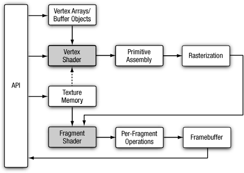
This chapter describes the OpenGL ES 2.0 programmable vertex pipeline. Figure 8-1 illustrates the OpenGL ES 2.0 programmable pipeline. The shaded boxes in Figure 8-1 indicate the programmable stages in OpenGL ES 2.0. In this chapter we discuss the vertex shader stage. Vertex shaders can be used to do traditional vertex-based operations such as transforming the position by a matrix, computing the lighting equation to generate a per-vertex color, and generating or transforming texture coordinates.
The previous chapters, specifically Chapter 5, “OpenGL ES Shading Language,” and Chapter 6, “Vertex Attributes, Vertex Arrays, and Buffer Objects,” discussed how to specify the vertex attribute and uniform inputs and also gave a good description of the OpenGL ES 2.0 shading language. In Chapter 7, “Primitive Assembly and Rasterization,” we discussed how the output of the vertex shader, referred to as varying variables, is used by the rasterization stage to generate per-fragment values, which are then input to the fragment shader. In this chapter we begin with a high-level overview of a vertex shader including its inputs and outputs. We then discuss some of the limitations imposed by the OpenGL ES 2.0 shading language and describe points to keep in mind when writing shaders that need to be portable across multiple OpenGL ES 2.0 implementations. We then describe how to write vertex shaders by discussing a few examples. These examples describe common use cases such as transforming a vertex position with a model view and projection matrix, examples of vertex lighting that generate per-vertex diffuse and specular colors, texture coordinate generation, and vertex skinning. We hope that these examples help the reader get a good idea of how to write vertex shaders, rules to keep in mind to make vertex shaders portable as much as possible, and an upper limit on how big vertex shaders can be. Last but not least, we describe a vertex shader that implements the OpenGL ES 1.1 fixed function vertex pipeline. These two shaders should also give the reader a good understanding of the complexity of vertex shaders that will be supported by the first generation of handheld devices that implement OpenGL ES 2.0.
The vertex shader provides a general-purpose programmable method for operating on vertices. Figure 8-2 shows the inputs and outputs of a vertex shader. The inputs to the vertex shader consist of the following:
Attributes—Per-vertex data supplied using vertex arrays.
Uniforms—Constant data used by the vertex shader.
Shader program—Vertex shader program source code or executable that describes the operations that will be performed on the vertex.
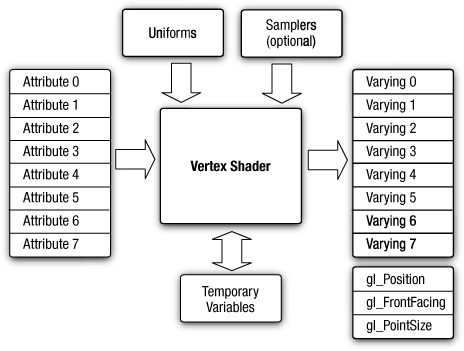
The outputs of the vertex shader are called varying variables. In the primitive rasterization stage, these variables are computed for each generated fragment and are passed in as inputs to the fragment shader.
The built-in variables of a vertex shader can be categorized into special variables that are output by the vertex shader, uniform state such as depth range, and constants that specify maximum values such as the number of attributes, number of varyings, and number of uniforms.
OpenGL ES 2.0 has built-in special variables that are either output by the vertex shader that then become input to the fragment shader, or are output by the fragment shader. The built-in special variables available to the vertex shader are as follows:
gl_Position—.gl_Positionis used to output the vertex position in clip coordinates. Thegl_Positionvalues are used by the clipping and viewport stages to perform appropriate clipping of primitives and convert the vertex position from clip coordinates to screen coordinates. The value ofgl_Positionis undefined if the vertex shader does not write togl_Position.gl_Positionis a floating-point variable declared using thehighpprecision qualifier.gl_PointSize—.gl_PointSizeis used to write the size of the point sprite in pixels.gl_PointSizeis used when point sprites are rendered. Thegl_PointSizevalue output by a vertex shader is then clamped to the aliased point size range supported by the OpenGL ES 2.0 implementation.gl_PointSizeis a floating-point variable declared using themediumpprecision qualifier.gl_FrontFacing—. This special variable, although not directly written by the vertex shader, is generated based on the position values generated by the vertex shader and primitive type being rendered.gl_FrontFacingis a boolean variable.
The only built-in uniform state available inside a vertex shader is the depth range in window coordinates. This is given by the built-in uniform name gl_DepthRange, which is declared as a uniform of type gl_DepthRangeParameters.
struct gl_DepthRangeParameters {
   highp float near; // near Z
   highp float far;  // far Z
   highp float diff; // far - near
}

uniform gl_DepthRangeParameters gl_DepthRange;The following built-in constants are also available inside the vertex shader.
const mediump int gl_MaxVertexAttribs             = 8;
const mediump int gl_MaxVertexUniformVectors      = 128;
const mediump int gl_MaxVaryingVectors            = 8;
const mediump int gl_MaxVertexTextureImageUnits   = 0;
const mediump int gl_MaxCombinedTextureImageUnits = 8;
The built-in constants describe the following maximum terms:
gl_MaxVertexAttribs—. This is the maximum number of vertex attributes that can be specified. The minimum value supported by all ES 2.0 implementations is eight.gl_MaxVertexUniformVectors—. This is the maximum number ofvec4uniform entries that can be used inside a vertex shader. The minimum value supported by all ES 2.0 implementations is128 vec4entries. The number of vec4 uniform entries that can actually be used by a developer can vary from implementation to implementation and from one vertex shader to another. For example, some implementations might count user-specified literal values used in a vertex shader against the uniform limit. In other cases, implementation-specific uniforms (or constants) might need to be included depending on whether the vertex shader makes use of any built-in transcendental functions. There currently is no mechanism that an application can use to find the number of uniform entries that it can use in a particular vertex shader. The vertex shader compilation will fail and there might be information in the compile log that provides specific information with regards to number of uniform entries being used. However, the information returned by the compile log is implementation specific. We provide some guidelines in this chapter to help maximize the use of vertex uniform entries available in a vertex shader.gl_MaxVaryingVectors—. This is the maximum number of varying vectors; that is, the number ofvec4entries that can be output by a vertex shader. The minimum value supported by all ES 2.0 implementations is eightvec4entries.gl_MaxVertexTextureImageUnits—. This is the maximum number of texture units available in a vertex shader. The minimum value is0, which implies that the implementation does not support a vertex texture fetch.gl_MaxCombinedTextureImageUnits—. This is the sum of the maximum number of texture units available in the vertex + fragment shaders. The minimum value is eight.
The values specified for each built-in constant are the minimum values that must be supported by all OpenGL ES 2.0 implementations. It is possible that implementations might support values greater than the minimum values described. The actual supported values can be queried using the following code.
GLint maxVertexAttribs, maxVertexUniforms, maxVaryings;
GLint maxVertexTextureUnits, maxCombinedTextureUnits;

glGetIntegerv(GL_MAX_VERTEX_ATTRIBS, &maxVertexAttribs);
glGetIntegerv(GL_MAX_VERTEX_UNIFORM_VECTORS, &maxVertexUniforms);
glGetIntegerv(GL_MAX_VARYING_VECTORS, &maxVaryings);
glGetIntegerv(GL_MAX_VERTEX_TEXTURE_IMAGE_UNITS,
              &maxVertexTextureUnits);
glGetIntegerv(GL_MAX_COMBINED_TEXTURE_IMAGE_UNITS,
&maxCombinedTextureUnits);We do a brief review of precision qualifiers. Precisions qualifiers are covered in Chapter 5. Precision qualifiers can be used to specify the precision of any float- or integer-based variable. The keywords for specifying the precision are lowp, mediump, and highp. Some examples of declarations with precision qualifiers are shown here.
highp vec4        position;
varying lowp vec4 color;
mediump float     specularExp;
In addition to precision qualifiers, there is also the notion of default precision. That is, if a variable is declared without having a precision qualifier, it will have the default precision for that type. The default precision qualifier is specified at the top of a vertex or fragment shader using the following syntax:
precision highp float;
precision mediump int;
The precision specified for float will be used as the default precision for all variables based on a floating-point value. Likewise, the precision specified for int will be used as the default precision for all integer-based variables. In the vertex shader, if no default precision is specified, the default precision for both int and float is highp.
For operations typically performed in a vertex shader, the precision qualifier that will most likely be needed is the highp precision qualifier. Operations that transform a position with a matrix, transform normals and texture coordinates, or generate texture coordinates will need to be done with highp precision. Color computations and lighting equations can most likely be done with mediump precision. Again, this will depend on the kind of color computations being performed and the range and precision required for operations that are being performed. We believe that highp will most likely be the default precision used for most operations in a vertex shader and therefore use highp as the default precision qualifier in the examples that follow.
In this section we describe the limitations imposed by the OpenGL ES 2.0 shading language for vertex shaders. These limitations should help developers write a portable vertex shader that should compile and run on most OpenGL ES 2.0 implementations.
There is no way to query the maximum number of instructions supported in a vertex shader across all OpenGL ES 2.0 implementations. It is therefore not possible to say with certainty whether a given vertex shader’s instruction count is less than or equal to the number of instructions supported in a vertex shader by an implementation. If the instruction count exceeds the maximum number of instructions allowed in a vertex shader, the vertex shader source will fail to compile.
The OpenGL ES working group recognizes that not being able to query the maximum instruction count and the actual number of uniforms available in a vertex shader are serious issues that can make developers’ lives somewhat difficult. The plan is to be able to provide a suite of vertex (and fragment) shaders that will help demonstrate the instruction complexity and uniform usage. In addition, this suite of shaders will be part of the OpenGL ES 2.0 conformance test, which means that all conformant OpenGL ES 2.0 implementations will be capable of running the shaders.
A temporary variable refers to a variable declared inside a function or a variable that stores an intermediate value. Because OpenGL ES shading language is a high-level language, there is no way to specify the minimum number of temporary variables that must be supported by all OpenGL ES 2.0 implementations. It is therefore possible that a vertex shader might run into this issue and not compile on all ES 2.0 implementations.
OpenGL ES 2.0 requires implementations to support for loops in a vertex shader without requiring that they must be unrolled. For example, you could have a for loop with a loop index that goes from 0 to 1023. This will typically not be unrolled by the shader compiler, as the code size of the unrolled shader will most likely be too big for most ES 2.0 implementations.
The following restrictions apply to for loops used in a vertex shader:
Only one loop index can be used in a
forloop.The loop index must be initialized to a constant integral expression.
The condition expression declared in the
forloop must be one of the following:loop_indx < constant_expression
loop_indx <= constant_expression
loop_indx > constant_expression
loop_indx >= constant_expression
loop_indx != constant_expression
loop_indx == constant_expression
The loop index can be modified in the
forloop statement using one of the following expressions only:loop_index--
loop_index++
loop_index -= constant_expression
loop_index += constant_expression
The loop index can be passed as a read-only argument to functions inside the
forloop (i.e., the loop index can be used with arguments declared using theinparameter qualifier).
Examples of valid for loop constructs are shown here.
const int numLights = 4;

int i, j;
for (i=0; i<numLights; i++)
{
   ...
}

for (j=4; j>0; j--)
{
   ...
   foo(j);  // argument to function foo that takes j
            // is declared with the in qualifier.
}
Examples of invalid for loop constructs are shown here.
uniform int numLights;

int i;
for (i=0; i<numLights; i++)  // conditional expression is
                             // not constant
{
   ...
}

for (i=0; i<8; i++)
{
   i = foo();   // return value of foo() cannot be
                // assigned to loop index i
}

for (j=4; j>0;)
{
   ...
   j--;   // loop index j cannot be modified
          // inside for loop
}
while and do-while loops, though specified by the OpenGL ES 2.0 shading language specification, are not a requirement and therefore might not be supported by all OpenGL ES 2.0 implementations.
The following conditional statements are fully supported without any restrictions.
if(bool_expression)
{
   ...
}

if(bool_expression)
{
   ...
}
else
{
   ...
}
bool_expression must be a scalar boolean value.
GPUs typically execute a vertex shader with multiple vertices or a fragment shader with multiple fragments in parallel. The number of vertices or fragments that are executed in parallel will depend on the GPU’s performance target. The bool_expression in the if and if-else conditional statements can have different values for the vertices or fragments being executed in parallel. This can impact performance as the number of vertices or fragments executed in parallel by the GPU is reduced. We recommend that for best performance, conditional statements should be used with bool_expression values that are the same for vertices or fragments being executed in parallel. This will be the case if a uniform expression is used.
Array indexing of uniforms (excluding samplers) is fully supported. The array index can be a constant, uniform, or computed value. Samplers can only be indexed using a constant integral expression. A constant integral expression is a literal value (e.g., 4), a const integer variable (e.g., const int sampler_indx = 3;), or a constant expression (e.g., 3 + sampler_indx).
Attribute matrices and vectors can be indexed using a constant integral expression. Indexing attribute matrices and vectors with a non-constant integral expression is not mandated. This, however, is a very useful feature. The following code shows a vertex shader that performs vertex skinning. a_matrixweights is a vertex attribute that stores the matrix weight, for up to four matrices.
attribute vec4   a_matrixweights;    // matrix weights
attribute vec4   a_matrixindices;    // matrix palette indices

int i;

for (i=0; i<=3; i++)
{
   float   m_wt = a_matrixweights[i];
   int     m_indx = int(a_matrixindices[i]) * 3;

   ...
}
The code a_matrixweights[i] and a_matrixindices[i] highlighted in bold is not required to be supported and can therefore fail to compile.
gl_MaxVertexUniformVectors describes the maximum number of uniforms that can be used in a vertex shader. The minimum value for gl_MaxVertexUniformVectors that must be supported by any compliant OpenGL ES 2.0 implementation is 128 vec4 entries. The uniform storage is used to store the following variables:
Variables declared with the uniform qualifier.
Const variables.
Literal values.
Implementation-specific constants
The number of uniform variables used in a vertex shader along with the variables declared with the const qualifier, literal values, and implementation-specific constants must fit in gl_MaxVertexUniformVectors as per the packing rules described in Chapter 5. If these do not fit, then the vertex shader will fail to compile. It is possible for a developer to apply the packing rules and determine the amount of uniform storage needed to store uniform variables, const variables, and literal values. It is not possible to determine the number of implementation-specific constants as this value will not only vary from implementation to implementation but will also change depending on which built-in shading language functions are being used by the vertex shader. Typically, the implementation-specific constants are required when built-in transcendental functions are used.
As far as literal values are concerned, the OpenGL ES 2.0 shading language spec states that no constant propagation is assumed. This means that multiple instances of the same literal value(s) will be counted multiple times. Understandably it is easier to use literal values such as 0.0 or 1.0 in a vertex shader, but our recommendation is that this be avoided as much as possible. Instead of using literal values, appropriate const variables should be declared. This avoids having the same literal value count multiple times, which might cause the vertex shader to fail to compile if vertex uniform storage requirements exceed what the implementation supports.
Consider the following example that describes a snippet of vertex shader code that transforms two texture coordinates per vertex:
#define NUM_TEXTURES   2

uniform mat4  tex_matrix[NUM_TEXTURES];        // texture matrices
uniform bool  enable_tex[NUM_TEXTURES];        // texture enables
uniform bool  enable_tex_matrix[NUM_TEXTURES]; // texture matrix
                                               // enables

attribute vec4  a_texcoord0;  // available if enable_tex[0] is true
attribute vec4  a_texcoord1;  // available if enable_tex[1] is true

varying vec4    v_texcoord[NUM_TEXTURES];

v_texcoord[0] = vec4(0.0, 0.0, 0.0, 1.0);
// is texture 0 enabled
if (enable_tex[0])
{
    // is texture matrix 0 enabled
    if(enable_tex_matrix[0])
       v_texcoord[0] = tex_matrix[0] * a_texcoord0;
    else
       v_texcoord[0] = a_texcoord0;
}

v_texcoord[1] = vec4(0.0, 0.0, 0.0, 1.0);
// is texture 1 enabled
if (enable_tex[1])
{
    // is texture matrix 1 enabled
    if(enable_tex_matrix[1])
       v_texcoord[1] = tex_matrix[1] * a_texcoord1;
    else
       v_texcoord[1] = a_texcoord1;
}
The code just described might result in each reference to the literal values 0, 1, 0.0, 1.0 counting against the uniform storage. To guarantee that these literal values count only once against the uniform storage, the vertex shader code snippet should be written as follows:
#define NUM_TEXTURES   2

const int  c_zero = 0;
const int  c_one  = 1;

uniform mat4  tex_matrix[NUM_TEXTURES];        // texture matrices
uniform bool  enable_tex[NUM_TEXTURES];        // texture enables
uniform bool  enable_tex_matrix[NUM_TEXTURES]; // texture matrix
                                               // enables
attribute vec4  a_texcoord0;  // available if enable_tex[0] is true
attribute vec4  a_texcoord1;  // available if enable_tex[1] is true

varying vec4    v_texcoord[NUM_TEXTURES];

v_texcoord[c_zero] = vec4(float(c_zero), float(c_zero),
                          float(c_zero), float(c_one));
// is texture 0 enabled
if(enable_tex[c_zero])
{
   // is texture matrix 0 enabled
   if(enable_tex_matrix[c_zero])
      v_texcoord[c_zero] = tex_matrix[c_zero] * a_texcoord0;
   else
      v_texcoord[c_zero] = a_texcoord0;
}

v_texcoord[c_one] = vec4(float(c_zero), float(c_zero),
                         float(c_zero), float(c_one));
// is texture 1 enabled
if(enable_tex[c_one])
{
   // is texture matrix 1 enabled
   if(enable_tex_matrix[c_one])
      v_texcoord[c_one] = tex_matrix[c_one] * a_texcoord1;
   else
      v_texcoord[c_one] = a_texcoord1;
}
Hopefully this section has been helpful in providing a good understanding of the limitations of the OpenGL ES 2.0 shading language and how to write vertex shaders that should compile and run on most OpenGL ES 2.0 implementations.
We now present a few examples that demonstrate how to implement the following features in a vertex shader:
Transforming vertex position with a matrix.
Lighting computations to generate per-vertex diffuse and specular color.
Texture coordinate generation.
Vertex skinning.
These features represent typical use cases that OpenGL ES 2.0 applications will want to perform in a vertex shader.
Example 8-1 describes a simple vertex shader written using the OpenGL ES shading language. The vertex shader takes a position and its associated color data as inputs or attributes, transforms the position by a 4 × 4 matrix and outputs the transformed position and color.
Example 8-1. A Simple Vertex Shader
// uniforms used by the vertex shader
uniform mat4    u_mvp_matrix; // matrix to convert P from
                              // model space to clip space.

// attributes input to the vertex shader
attribute vec4  a_position;   // input position value
attribute vec4  a_color;      // input vertex color

// varying variables - input to the fragment shader
varying vec4    v_color;      // output vertex color

void
main()
{
   v_color = a_color;
   gl_Position = u_mvp_matrix * a_position;
}
The transformed vertex positions and primitive type are then used by the setup and rasterization stages to rasterize the primitive into fragments. For each fragment, the interpolated v_color will be computed and passed as input to the fragment shader.
In this section, we look at examples that compute the lighting equation for directional lights and point, spot lights. The vertex shaders described in this section use the OpenGL ES 1.1 lighting equation model to compute the lighting equation for a directional or a spot (or point) light. In the lighting examples described here, the viewer is assumed to be at infinity.
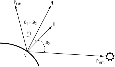
A directional light is a light source that is at an infinite distance from the objects in the scene being lit. An example of a directional light is the sun. As the light is at infinite distance, the light rays from the light source are parallel. The light direction vector is a constant and does not need to be computed per vertex. Figure 8-3 describes the terms that are needed in computing the lighting equation for a directional light. Peye is the position of the viewer, Plight is the position of the light (Plight .w = 0), N is the normal, and H is the half-plane vector. Because Plight . w = 0, the light direction vector will be Plight . xyz. The half-plane vector H is computed as || VPlight + VPeye ||. As both the light source and viewer are at infinity, the half-plane vector H = || Plight . xyz + (0, 0, 1) ||.
Example 8-2 describes the vertex shader code that computes the lighting equation for a directional light. The directional light properties are described by a directional_light struct that contains the following elements:
direction—. The normalized light direction in eye space.halfplane—. The normalized half-plane vector H. This can be precomputed for a directional light, as it does not change.ambient_color—. The ambient color of the light.diffuse_color—. The diffuse color of the light.specular_color—. The specular color of the light.
The material properties needed to compute the vertex diffuse and specular color are described by a material_properties struct that contains the following elements:
diffuse_color—. The diffuse color of the material.specular_color—. The specular color of the material.specular_exponent—. The specular exponent that describes the shininess of the material and is used to control the shininess of the specular highlight.
Example 8-2. Directional Light
struct directional_light {
   vec3  direction;     // normalized light direction in eye space
   vec3  halfplane;     // normalized half-plane vector
   vec4  ambient_color;
   vec4  diffuse_color;
   vec4  specular_color;
};

struct material_properties {
   vec4   ambient_color;
   vec4   diffuse_color;
   vec4   specular_color;
   float  specular_exponent;
};

const float                  c_zero = 0.0;
const float                  c_one = 1.0;

uniform material_properties  material;
uniform directional_light    light;

// normal has been transformed into eye space and is a normalized
// value returns the computed color.
vec4
directional_light(vec3 normal)
{
   vec4   computed_color = vec4(c_zero, c_zero, c_zero, c_zero);
   float  ndotl;  // dot product of normal & light direction
   float  ndoth;  // dot product of normal & half-plane vector

   ndotl = max(c_zero, dot(normal, light.direction));
   ndoth = max(c_zero, dot(normal, light.halfplane));

   computed_color += (light.ambient_color * material.ambient_color);
   computed_color += (ndotl * light.diffuse_color
                      * material.diffuse_color);
   if (ndoth > c_zero)
   {
      computed_color += (pow(ndoth, material.specular_exponent) *
                         material.specular_color *
                         light.specular_color);
   }

   return computed_color;
}
The directional light vertex shader code described in Example 8-2 combines the per-vertex diffuse and specular color into a single color (given by computed_color). Another option would be to compute the per-vertex diffuse and specular colors and pass them as separate varying variables to the fragment shader.
Note
In Example 8-2 we multiply the material colors (ambient, diffuse, and specular) with the light colors. This is fine if we are computing the lighting equation for only one light. If we have to compute the lighting equation for multiple lights, we should compute the ambient, diffuse, and specular values for each light and then compute the final vertex color by multiplying the material ambient, diffuse, and specular colors to appropriate computed terms and then summing them all to generate a per-vertex color.
A point light is a light source that emanates light in all directions from a position in space. A point light is given by a position vector (x, y, z, w), where w ≠ 0. The point light shines evenly in all directions but its intensity falls off (i.e., gets attenuated) based on the distance from the light to the object. This attenuation is computed using the following equation:
distance attenuation = 1 / (K0 + K1 × ‖ VPlight ‖ + K2 × ‖ VPlight ‖2)
K0, K1, and K2 are the constant, linear, and quadratic attenuation factors.
A spotlight is a light source with both a position and a direction that simulates a cone of light emitted from a position (Plight) in a direction (given by spotdirection). Figure 8-4 describes the terms that are needed in computing the lighting equation for a spotlight.

The intensity of the emitted light is attenuated by a spot cutoff factor based on the angle from the center of the cone. This angle from the center of the cone is computed as the dot product of VPlight and spotdirection. The spot cutoff factor is 1.0 in the spot light direction given by spotdirection and falls off exponentially to 0.0 spotcutoff angle radians away.
Example 8-3 describes the vertex shader code that computes the lighting equation for a spot (and point) light. The spot light properties are described by a spot_light struct that contains the following elements:
direction—. The light direction in eye space.ambient_color—. The ambient color of the light.diffuse_color—. The diffuse color of the light.specular_color—. The specular color of the light.attenuation_factors—. The distance attenuation factors K0, K1, and K2.compute_distance_attenuation—. This boolean term determines if the distance attenuation must be computed.spot_direction—. The normalized spot direction vector.spot_exponent—. The spotlight exponent used to compute the spot cutoff factor.spot_cutoff_angle—. The spotlight cutoff angle in degrees.
Example 8-3. Spot Light
struct spot_light {
   vec4    position;            // light position in eye space
   vec4    ambient_color;
   vec4    diffuse_color;
   vec4    specular_color;
   vec3    spot_direction;      // normalized spot direction
   vec3    attenuation_factors; // attenuation factors K0, K1, K2
   bool    compute_distance_attenuation;
   float   spot_exponent;       // spotlight exponent term
   float   spot_cutoff_angle;   // spot cutoff angle in degrees
};

struct material_properties {
   vec4    ambient_color;
   vec4    diffuse_color;
   vec4    specular_color;
   float   specular_exponent;
};

const float                  c_zero = 0.0;
const float                  c_one = 1.0;

uniform material_properties  material;
uniform spot_light           light;

// normal and position are normal and position values in eye space.
// normal is a normalized vector.
// returns the computed color.

vec4
spot_light(vec3 normal, vec4 position)
{
   vec4    computed_color = vec4(c_zero, c_zero, c_zero, c_zero);
   vec3    lightdir;
   vec3    halfplane;
   float   ndotl, ndoth;
   float   att_factor;

   att_factor = c_one;

   // we assume "w" values for light position and
   // vertex position are the same
   lightdir = light.position.xyz - position.xyz;

   // compute distance attenuation
   if(light.compute_distance_attenuation)
   {
       vec3    att_dist;

       att_dist.x = c_one;
       att_dist.z = dot(lightdir, lightdir);
       att_dist.y = sqrt(att_dist.z);
       att_factor = c_one / dot(att_dist, light.attenuation_factors);
   }

   // normalize the light direction vector
   lightdir = normalize(lightdir);

   // compute spot cutoff factor
   if(light.spot_cutoff_angle < 180.0)
   {
       float  spot_factor = dot(-lightdir, light.spot_direction);

       if(spot_factor >= cos(radians(light.spot_cutoff_angle)))
          spot_factor = pow(spot_factor, light.spot_exponent);
       else
          spot_factor = c_zero;

       // compute combined distance & spot attenuation factor
       att_factor *= spot_factor;
    }

    if(att_factor > c_zero)
    {
       // process lighting equation --> compute the light color
       computed_color += (light.ambient_color *
                          material.ambient_color);
       ndotl = max(c_zero, dot(normal, lightdir));
       computed_color += (ndotl * light.diffuse_color *
                          material.diffuse_color);
       halfplane = normalize(lightdir + vec3(c_zero, c_zero, c_one));
       ndoth = dot(normal, halfplane);
       if (ndoth > c_zero)
       {
          computed_color += (pow(ndoth, material.specular_exponent)*
                             material.specular_color *
                             light.specular_color);
       }

       // multiply color with computed attenuation
       computed_color *= att_factor;
    }

    return computed_color;
}We look at two examples that generate texture coordinates in a vertex shader. The two examples are used when rendering shiny (i.e., reflective) objects in a scene by generating a reflection vector and then using this to compute a texture coordinate that indexes into a latitude longitude map (also called a sphere map) or a cube map (represents six views or faces that capture reflected environment assuming a single viewpoint in the middle of the shiny object). The OpenGL 2.0 specification describes the texture coordinate generation modes as GL_SPHERE_MAP and GL_REFLECTION_MAP, respectively. The GL_SPHERE_MAP mode generates a texture coordinate that uses a reflection vector to compute a 2D texture coordinate for lookup into a 2D texture map. The GL_REFLECTION_MAP mode generates a texture coordinate that is a reflection vector that can be used as a 3D texture coordinate for lookup into a cube map. Examples 8-4 and 8-5 describe the vertex shader code that generates texture coordinates that will be used by the appropriate fragment shader to calculate the reflected image on the shiny object.
Example 8-4. Sphere Map Texture Coordinate Generation
// position is the normalized position coordinate in eye space
// normal is the normalized normal coordinate in eye space
// returns a vec2 texture coordinate
vec2
sphere_map(vec3 position, vec3 normal)
{
   reflection = reflect(position, normal);
   m = 2.0 * sqrt(reflection.x * reflection.x +
                  reflection.y * reflection.y +
                  (reflection.z + 1.0) * (reflection.z + 1.0));
   return vec2((reflection.x / m + 0.5), (reflection.y / m + 0.5));
}
Example 8-5. Cube Map Texture Coordinate Generation
// position is the normalized position coordinate in eye space
// normal is the normalized normal coordinate in eye space
// returns the reflection vector as a vec3 texture coordinate
vec3
cube_map(vec3 position, vec3 normal)
{
   return reflect(position, normal);
}
The reflection vector will then be used inside a fragment shader as the texture coordinate to the appropriate cube map.
Vertex skinning is a commonly used technique whereby the joins between polygons are smoothed. This is implemented by applying additional transform matrices with appropriate weights to each vertex. The multiple matrices used to skin vertices are stored in a matrix palette. Matrices indices per vertex are used to refer to appropriate matrices in the matrix palette that will be used to skin the vertex. Vertex skinning is commonly used for character models in 3D games to ensure that they appear smooth and realistic (as much as possible) without having to use additional geometry. The number of matrices used to skin a vertex is typically two to four.
The mathematics of vertex skinning is given by the following equations:

where
n is the number of matrices that will be used to transform the vertex
P is the vertex position
P′ is the transformed (skinned) position
N is the vertex normal
N′ is the transformed (skinned) normal
Mi is the matrix associated with the ith matrix per vertex and is computed as
Mi = matrix_palette [ matrix_index[i] ] with n matrix_index values specified per vertex
Mi-1T is the inverse transpose of matrix Mi
wi is the weight associated with the matrix
We discuss how to implement vertex skinning with a matrix palette of 32 matrices and up to four matrices per vertex to generate a skinned vertex. A matrix palette size of 32 matrices is quite common. The matrices in the matrix palette typically are 4 × 3 column major matrices (i.e., four vec3 entries per matrix). If the matrices were to be stored in column-major order, this will take 128 uniform entries with three elements of each uniform entry used to store a row. The minimum value of gl_MaxVertexUniformVectors that is supported by all OpenGL ES 2.0 implementations is 128 vec4 entries. This means we will only have the fourth row of these 128 vec4 uniform entries available. This row of floats can only be used to store uniforms declared to be of type float (as per the uniform packing rule). There is no room therefore to store a vec2, vec3, or vec4 uniform. It would be better to store the matrices in the palette in row-major order using three vec4 entries per matrix. If we did this, then we use 96 vec4’s of uniform storage and the remaining 32 vec4 entries can be used to store other uniforms. Note that we do not have enough uniform storage to store inverse transpose matrices needed to compute the skinned normal. This is typically not a problem as in most cases the matrices used are orthonormal and therefore can be used to transform the vertex position and the normal.
Example 8-6 describes the vertex shader code that computes the skinned normal and position. We assume 32 matrices in the matrix palette, and that the matrices are stored in row-major order. The matrices are also assumed to be orthonormal (i.e., the same matrix can be used to transform position and normal) and up to four matrices are used to transform each vertex.
Example 8-6. Vertex Skinning Shader with No Check to See if Matrix Weight = 0
#define NUM_MATRICES  32  // 32 matrices in matrix palette

const int       c_zero  = 0;
const int       c_one   = 1;
const int       c_two   = 2;
const int       c_three = 3;

// store 32 4 x 3 matrices as an array of floats representing
// each matrix in row-major order i.e. 3 vec4s
uniform vec4    matrix_palette[NUM_MATRICES * 3];

// vertex position and normal attributes
attribute vec4  a_position
attribute vec3  a_normal;

// matrix weights - 4 entries / vertex
attribute vec4  a_matrixweights;
// matrix palette indices
attribute vec4  a_matrixindices;

void
skin_position(in vec4 position, float m_wt, int m_indx,
                                out vec4 skinned_position)
{
   vec4    tmp;

   tmp.x = dot(position, matrix_palette[m_indx]);
   tmp.y = dot(position, matrix_palette[m_indx + c_one]);
   tmp.z = dot(position, matrix_palette[m_indx + c_two]);
   tmp.w = position.w;

   skinned_position += m_wt * tmp;
}

void
skin_normal(in vec3 normal, float m_wt, int m_indx,
                                out vec3 skinned_normal)
{
   vec3    tmp;

   tmp.x = dot(normal, matrix_palette[m_indx].xyz);
   tmp.y = dot(normal, matrix_palette[m_indx + c_one].xyz);
   tmp.z = dot(normal, matrix_palette[m_indx + c_two].xyz);

   skinned_position += m_wt * tmp;
}


void
do_skinning(in vec4 position, in vec3 normal,
            out vec4 skinned_position, out vec4 skinned_normal)
{
   skinned_position = vec4(float(c_zero));
   skinned_normal = vec3(float(c_zero));

   // transform position and normal to eye space using matrix
   // palette with four matrices used to transform a vertex

   m_wt = a_matrixweights[0];
   m_indx = int(a_matrixindices[0]) * c_three;
   skin_position(position, m_wt, m_indx, skinned_position);
   skin_normal(normal, m_wt, m_indx, skinned_normal);

   m_wt = a_matrixweights[1];
   m_indx = int(a_matrixindices[1]) * c_three;
   skin_position(position, m_wt, m_indx, skinned_position);
   skin_normal(normal, m_wt, m_indx, skinned_normal);

   m_wt = a_matrixweights[2];
   m_indx = int(a_matrixindices[2]) * c_three;
   skin_position(position, m_wt, m_indx, skinned_position);
   skin_normal(normal, m_wt, m_indx, skinned_normal);

   m_wt = a_matrixweights[3];
   m_indx = int(a_matrixindices[3]) * c_three;
   skin_position(position, m_wt, m_indx, skinned_position);
   skin_normal(normal, m_wt, m_indx, skinned_normal);

}
In Example 8-6, the vertex skinning shader generates a skinned vertex by transforming a vertex with four matrices and appropriate matrix weights. It is possible and quite common that some of these matrix weights may be zero. In Example 8-6, the vertex is transformed using all four matrices, irrespective of their weights. It might be better to use a conditional expression to check if matrix weight is zero before calling skin_position and skin_normal. Example 8-7 describes the vertex skinning shader that checks if the matrix weight is zero before applying the matrix transformation.
Example 8-7. Vertex Skinning Shader with Checks to See if Matrix Weight = 0
void
do_skinning(in vec4 position, in vec3 normal,
            out vec4 skinned_position, out vec4 skinned_normal)
{
   skinned_position = vec4(float(c_zero));
   skinned_normal = vec3(float(c_zero));

   // transform position and normal to eye space using matrix
   // palette with four matrices used to transform a vertex

   m_wt = a_matrixweights[0];
   if(m_wt > 0.0)
   {
       m_indx = int(a_matrixindices[0]) * c_three;
       skin_position(position, m_wt, m_indx, skinned_position);
       skin_normal(normal, m_wt, m_indx, skinned_normal);
   }

   m_wt = a_matrixweights[1];
   if(m_wt > 0.0)
   {
       m_indx = int(a_matrixindices[1]) * c_three;
       skin_position(position, m_wt, m_indx, skinned_position);
       skin_normal(normal, m_wt, m_indx, skinned_normal);
   }

   m_wt = a_matrixweights[2];
   if(m_wt > 0.0)
   {
       m_indx = int(a_matrixindices[2]) * c_three;
       skin_position(position, m_wt, m_indx, skinned_position);
       skin_normal(normal, m_wt, m_indx, skinned_normal);
   }

   m_wt = a_matrixweights[3];
   if(m_wt > 0.0)
   {
       m_indx = int(a_matrixindices[3]) * c_three;
       skin_position(position, m_wt, m_indx, skinned_position);
       skin_normal(normal, m_wt, m_indx, skinned_normal);
   }
}
At first glance, we might conclude that the vertex skinning shader in Example 8-7 has better performance than the vertex skinning shader in Example 8-6. This is not necessarily true and the answer can vary across GPUs. This is because in the conditional expression if (m_wt > 0.0), m_wt is a dynamic value and can be different for vertices being executed in parallel by the GPU. We now run into divergent flow control where vertices being executed in parallel may have different values for m_wt and this can cause execution to serialize. If a GPU does not implement divergent flow control efficiently, the vertex shader in Example 8-7 might not be as efficient as the version in Example 8-6. Applications should, therefore, test performance of divergent flow control by executing a test shader on the GPU as part of the application initialization phase to determine which shaders to use.
We hope that the examples discussed so far have provided a good understanding of vertex shaders, how to write them, and how to use them for a wide-ranging array of effects.
We now discuss a vertex shader that implements the OpenGL ES 1.1 fixed function vertex pipeline without vertex skinning. This is also meant to be an interesting exercise in figuring out how big a vertex shader can be for it to run across all OpenGL ES 2.0 implementations.
This vertex shader implements the following fixed functions of the OpenGL ES 1.1 vertex pipeline:
Transform the normal and position to eye space, if required (typically required for lighting). Rescale or normalization of normal is also performed.
Computes the OpenGL ES 1.1 vertex lighting equation for up to eight directional, point, or spot lights with two-sided lighting and color material per vertex.
Transform texture coordinates for up to two texture coordinates per vertex.
Compute fog factor passed to fragment shader. The fragment shader uses the fog factor to interpolate between fog color and vertex color.
Computes per-vertex user clip plane factor. Only one user clip plane is supported.
Transform position to clip space.
Example 8-8 is the vertex shader that implements the OpenGL ES 1.1 fixed function vertex pipeline as already described.
Example 8-8. OpenGL ES 1.1 Fixed Function Vertex Pipeline
//******************************************************************
//
// OpenGL ES 2.0 vertex shader that implements the following
// OpenGL ES 1.1 fixed function pipeline
//
// - compute lighting equation for up to eight directional/point/
// - spot lights
// - transform position to clip coordinates
// - texture coordinate transforms for up to two texture coordinates
// - compute fog factor
// - compute user clip plane dot product (stored as v_ucp_factor)
//
//******************************************************************
#define NUM_TEXTURES                2
#define GLI_FOG_MODE_LINEAR         0
#define GLI_FOG_MODE_EXP            1
#define GLI_FOG_MODE_EXP2           2

struct light {
   vec4    position;  // light position for a point/spot light or
                      // normalized dir. for a directional light
   vec4    ambient_color;
   vec4    diffuse_color;
   vec4    specular_color;
   vec3    spot_direction;
   vec3    attenuation_factors;
   float   spot_exponent;
   float   spot_cutoff_angle;
   bool    compute_distance_attenuation;
};

struct material {
   vec4    ambient_color;
   vec4    diffuse_color;
   vec4    specular_color;
   vec4    emissive_color;
   float   specular_exponent;
};

const float       c_zero = 0.0;
const float       c_one = 1.0;
const int         indx_zero = 0;
const int         indx_one = 1;

uniform mat4      mvp_matrix;   // combined model-view +
                                // projection matrix

uniform mat4      modelview_matrix;     // model view matrix
uniform mat3      inv_modelview_matrix; // inverse model-view
                                        // matrix used
// to transform normal
uniform mat4      tex_matrix[NUM_TEXTURES]; // texture matrices
uniform bool      enable_tex[NUM_TEXTURES]; // texture enables
uniform bool      enable_tex_matrix[NUM_TEXTURES]; // texture matrix
                                                   // enables

uniform material  material_state;
uniform vec4      ambient_scene_color;
uniform light     light_state[8];
uniform bool      light_enable_state[8];  // booleans to indicate
                                          // which of eight
                                          // lights are enabled
uniform int       num_lights;// number of lights enabled = sum of
                             // light_enable_state bools set to TRUE

uniform bool      enable_lighting;        // is lighting enabled
uniform bool      light_model_two_sided;  // is two-sided lighting
                                          // enabled
uniform bool      enable_color_material;  // is color material
                                          // enabled

uniform bool      enable_fog;             // is fog enabled
uniform float     fog_density;
uniform float     fog_start, fog_end;
uniform int       fog_mode;               // fog mode - linear, exp,
                                          // or exp2

uniform bool      xform_eye_p;   // xform_eye_p is set if we need
                                 // Peye for user clip plane,
                                 // lighting, or fog
uniform bool      rescale_normal;     // is rescale normal enabled
uniform bool      normalize_normal;   // is normalize normal enabled
uniform float     rescale_normal_factor; // rescale normal factor if
                                      // glEnable(GL_RESCALE_NORMAL)

uniform vec4      ucp_eqn;       // user clip plane equation -
                                 // - one user clip plane specified

uniform bool      enable_ucp;    // is user clip plane enabled

//******************************************************
// vertex attributes - not all of them may be passed in
//******************************************************
attribute vec4     a_position; // this attribute is always specified
attribute vec4     a_texcoord0;// available if enable_tex[0] is true
attribute vec4     a_texcoord1;// available if enable_tex[1] is true
attribute vec4     a_color;    // available if !enable_lighting or
                       // (enable_lighting && enable_color_material)
attribute vec3     a_normal;   // available if xform_normal is set
                               // (required for lighting)

//************************************************
// varying variables output by the vertex shader
//************************************************
varying vec4        v_texcoord[NUM_TEXTURES];
varying vec4        v_front_color;
varying vec4        v_back_color;
varying float       v_fog_factor;
varying float       v_ucp_factor;
//************************************************
// temporary variables used by the vertex shader
//************************************************
vec4                p_eye;
vec3                n;
vec4                mat_ambient_color;
vec4                mat_diffuse_color;

vec4
lighting_equation(int i)
{
   vec4    computed_color = vec4(c_zero, c_zero, c_zero, c_zero);
   vec3    h_vec;
   float   ndotl, ndoth;
   float   att_factor;

   att_factor = c_one;
   if(light_state[i].position.w != c_zero)
   {
      float   spot_factor;
      vec3    att_dist;
      vec3    VPpli;

      // this is a point or spot light
      // we assume "w" values for PPli and V are the same
      VPpli = light_state[i].position.xyz - p_eye.xyz;
      if(light_state[i].compute_distance_attenuation)
      {
          // compute distance attenuation
          att_dist.x = c_one;
          att_dist.z = dot(VPpli, VPpli);
          att_dist.y = sqrt(att_dist.z);
          att_factor = c_one / dot(att_dist,
             light_state[i].attenuation_factors);
      }
      VPpli = normalize(VPpli);

      if(light_state[i].spot_cutoff_angle < 180.0)
      {
         // compute spot factor
         spot_factor = dot(-VPpli, light_state[i].spot_direction);
         if(spot_factor >= cos(radians(
                               light_state[i].spot_cutoff_angle)))
            spot_factor = pow(spot_factor,
                              light_state[i].spot_exponent);
         else
            spot_factor = c_zero;

         att_factor *= spot_factor;
       }
    }
    else
    {
       // directional light
       VPpli = light_state[i].position.xyz;
    }

    if(att_factor > c_zero)
    {
       // process lighting equation --> compute the light color
       computed_color += (light_state[i].ambient_color *
                          mat_ambient_color);
       ndotl = max(c_zero, dot(n, VPpli));
       computed_color += (ndotl * light_state[i].diffuse_color *
                          mat_diffuse_color);
       h_vec = normalize(VPpli + vec3(c_zero, c_zero, c_one));
       ndoth = dot(n, h_vec);
       if (ndoth > c_zero)
       {
          computed_color += (pow(ndoth,
                             material_state.specular_exponent) *
                             material_state.specular_color *
                             light_state[i].specular_color);
       }
       computed_color *= att_factor; // multiply color with
                                     // computed attenuation factor
                                     // * computed spot factor
    }
    return computed_color;
}

float
compute_fog()
{
   float   f;

   // use eye Z as approximation
   if(fog_mode == GLI_FOG_MODE_LINEAR)
   {
      f = (fog_end - p_eye.z) / (fog_end - fog_start);
   }
   else if(fog_mode == GLI_FOG_MODE_EXP)
   {
       f = exp(-(p_eye.z * fog_density));
   }
   else
   {
       f = (p_eye.z * fog_density);
       f = exp(-(f * f));
   }

   f = clamp(f, c_zero, c_one);
   return f;
}

vec4
do_lighting()
{
   vec4    vtx_color;
   int     i, j;

   vtx_color = material_state.emissive_color +
               (mat_ambient_color * ambient_scene_color);
   j = (int)c_zero;
   for (i=(int)c_zero; i<8; i++)
   {
      if(j >= num_lights)
         break;

      if (light_enable_state[i])
      {
         j++;
         vtx_color += lighting_equation(i);
      }
   }

   vtx_color.a = mat_diffuse_color.a;

   return vtx_color;
}


void
main(void)
{
   int      i, j;

   // do we need to transform P
   if(xform_eye_p)
      p_eye = modelview_matrix * a_position;

   if(enable_lighting)
   {
      n = inv_modelview_matrix * a_normal;
      if(rescale_normal)
         n = rescale_normal_factor * n;
      if (normalize_normal)
            n = normalize(n);
      mat_ambient_color = enable_color_material ? a_color
                                    : material_state.ambient_color;
      mat_diffuse_color = enable_color_material ? a_color
                                    : material_state.diffuse_color;
      v_front_color = do_lighting();
      v_back_color = v_front_color;

      // do 2-sided lighting
      if(light_model_two_sided)
      {
         n = -n;
         v_back_color = do_lighting();
      }
   }
   else
   {
      // set the default output color to be the per-vertex /
      // per-primitive color
      v_front_color = a_color;
      v_back_color = a_color;
   }

   // do texture xforms
   v_texcoord[indx_zero] = vec4(c_zero, c_zero, c_zero, c_one);
   if(enable_tex[indx_zero])
   {
      if(enable_tex_matrix[indx_zero])
         v_texcoord[indx_zero] = tex_matrix[indx_zero] *
                                 a_texcoord0;
      else
         v_texcoord[indx_zero] = a_texcoord0;
   }

   v_texcoord[indx_one] = vec4(c_zero, c_zero, c_zero, c_one);
   if(enable_tex[indx_one])
   {
      if(enable_tex_matrix[indx_one])
         v_texcoord[indx_one] = tex_matrix[indx_one] * a_texcoord1;
      else
         v_texcoord[indx_one] = a_texcoord1;
   }

   v_ucp_factor = enable_ucp ? dot(p_eye, ucp_eqn) : c_zero;
   v_fog_factor = enable_fog ? compute_fog() : c_one;

   gl_Position = mvp_matrix * a_position;
}