
Chapter 8. Texture Mapping: The Basics
WHAT YOU’LL LEARN IN THIS CHAPTER:

In the preceding chapter, we covered in detail the groundwork for loading image data into OpenGL. Image data, unless modified by pixel zoom, generally has a one-to-one correspondence between a pixel in an image and a pixel on the screen. In fact, this is where we get the term pixel (picture element). In this chapter, we extend this knowledge further by applying images to three-dimensional primitives. When we apply image data to a geometric primitive, we call this a texture or texture map. Figure 8.1 shows the dramatic difference that can be achieved by texture mapping geometry. The cube on the left is a lit and shaded featureless surface, whereas the cube on the right shows a richness in detail that can be reasonably achieved only with texture mapping.
Figure 8.1. The stark contrast between textured and untextured geometry.

A texture image when loaded has the same makeup and arrangement as pixmaps, but now a one-to-one correspondence seldom exists between texels (the individual picture elements in a texture) and pixels on the screen. This chapter covers the basics of loading a texture map into memory and all the ways in which it may be mapped to and applied to geometric primitives.
Loading Textures
The first necessary step in applying a texture map to geometry is to load the texture into memory. Once loaded, the texture becomes part of the current texture state (more on this later). Three OpenGL functions are most often used to load texture data from a memory buffer (which is, for example, read from a disk file):
void glTexImage1D(GLenum target, GLint level, GLint internalformat,
GLsizei width, GLint border,
GLenum format, GLenum type, void *data);
void glTexImage2D(GLenum target, GLint level, GLint internalformat,
GLsizei width, GLsizei height, GLint border,
GLenum format, GLenum type, void *data);
void glTexImage3D(GLenum target, GLint level, GLint internalformat,
GLsizei width, GLsizei height, GLsizei depth, GLint border,
GLenum format, GLenum type, void *data);
These three rather lengthy functions tell OpenGL everything it needs to know about how to interpret the texture data pointed to by the data parameter.
The first thing you should notice about these functions is that they are essentially three flavors of the same root function, glTexImage. OpenGL supports one-, two-, and three-dimensional texture maps and uses the corresponding function to load that texture and make it current. You should also be aware that OpenGL copies the texture information from data when you call one of these functions. This data copy can be quite expensive, and in the section “Texture Objects,” later in this chapter, we discuss some ways to help mitigate this problem.
The target argument for these functions should be GL_TEXTURE_1D, GL_TEXTURE_2D, or GL_TEXTURE_3D, respectively. You may also specify proxy textures in the same manner in which you used proxies in the preceding chapter, by specifying GL_PROXY_TEXTURE_1D, GL_PROXY_TEXTURE_2D, or GL_PROXY_TEXTURE_3D and using the function glGetTexParameter to retrieve the results of the proxy query.
The level parameter specifies the mipmap level being loaded. Mipmaps are covered in an upcoming section called “Mipmapping,” so for nonmipmapped textures (just your plain old ordinary texture mapping), always set this to 0 (zero) for the moment.
Next, you have to specify the internalformat parameter of the texture data. This information tells OpenGL how many color components you want stored per texel and possibly the storage size of the components and/or whether you want the texture compressed (see the next chapter for information about texture compression). Table 8.1 lists the most common values for this function. A complete listing is given in Appendix C, “API Reference.”
Table 8.1. Most Common Texture Internal Formats

The width, height, and depth parameters (where appropriate) specify the dimensions of the texture being loaded. It is important to note that prior to OpenGL 2.0, these dimensions must be integer powers of 2 (1, 2, 4, 8, 16, 32, 64, and so on). There is no requirement that texture maps be square (all dimensions equal), but a texture loaded with non–power of 2 dimensions on older OpenGL implementations will cause texturing to be implicitly disabled. Even though OpenGL 2.0 (and later) allows non–power of two textures, this is no guarantee that they will necessarily be fast on the underlying hardware. Many performance-minded developers still avoid non–power of two textures for this reason.
The border parameter allows you to specify a border width for texture maps. Texture borders allow you to extend the width, height, or depth of a texture map by an extra set of texels along the borders. Texture borders play an important role in the discussion of texture filtering to come. For the time being, always set this value to 0 (zero).
The last three parameters—format, type, and data—are identical to the corresponding arguments when you used glDrawPixels to place image data into the color buffer. For the sake of convenience, we list the valid constants for format and type in Tables 8.2 and 8.3.
Table 8.2. Texel Formats for glTexImage
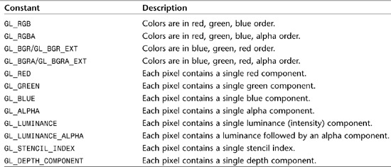
Table 8.3. Data Types for Pixel Data

Loaded textures are not applied to geometry unless the appropriate texture state is enabled. You can call glEnable or glDisable with GL_TEXTURE_1D, GL_TEXTURE_2D, or GL_TEXTURE_3D to turn texturing on or off for a given texture state. Only one of these texture states may be on at a time for a given texture unit (see the next chapter for a discussion of multitexturing).
A final word about texture loading: Texture data loaded by the glTexImage functions goes through the same pixel and imaging pipeline covered in the preceding chapter. This means pixel packing, pixel zoom, color tables, convolutions, and so on are applied to the texture data when it is loaded.
Using the Color Buffer
One- and two-dimensional textures may also be loaded using data from the color buffer. You can read an image from the color buffer and use it as a new texture by using the following two functions:
void glCopyTexImage1D(GLenum target, GLint level, GLenum internalformat,
GLint x, GLint y,
GLsizei width, GLint border);
void glCopyTexImage2D(GLenum target, GLint level, GLenum internalformat,
GLint x, GLint y,
GLsizei width, GLsizei height, GLint border);
These functions operate similarly to glTexImage, but in this case, x and y specify the location in the color buffer to begin reading the texture data. The source buffer is set using glReadBuffer and behaves just like glReadPixels. Note that there is no glCopyTexImage3D, because you can’t get volumetric data from a 2D color buffer!
Updating Textures
Repeatedly loading new textures can become a performance bottleneck in time-sensitive applications such as games or simulation applications. If a loaded texture map is no longer needed, it may be replaced entirely or in part. Replacing a texture map can often be done much more quickly than reloading a new texture directly with glTexImage. The function you use to accomplish this is glTexSubImage, again in three variations:
void glTexSubImage1D(GLenum target, GLint level,
GLint xOffset,
GLsizei width,
GLenum format, GLenum type, const GLvoid *data);
void glTexSubImage2D(GLenum target, GLint level,
GLint xOffset, GLint yOffset,
GLsizei width, GLsizei height,
GLenum format, GLenum type, const GLvoid *data);
void glTexSubImage3D(GLenum target, GLint level,
GLint xOffset, GLint yOffset, GLint zOffset,
GLsizei width, GLsizei height, GLsizei depth,
GLenum format, GLenum type, const GLvoid *data);
Most of the arguments correspond exactly to the parameters used in glTexImage. The xOffset, yOffset, and zOffset parameters specify the offsets into the existing texture map to begin replacing texture data. The width, height, and depth values specify the dimensions of the texture being “inserted” into the existing texture.
A final set of functions allows you to combine reading from the color buffer and inserting or replacing part of a texture. These glCopyTexSubImage variations do just that:
void glCopyTexSubImage1D(GLenum target, GLint level,
GLint xoffset,
GLint x, GLint y,
GLsizei width);
void glCopyTexSubImage2D(GLenum target, GLint level,
GLint xoffset, GLint yoffset,
GLint x, GLint y,
GLsizei width, GLsizei height);
void glCopyTexSubImage3D(GLenum target, GLint level,
GLint xoffset, GLint yoffset, Glint zoffset,
GLint x, GLint y,
GLsizei width, GLsizei height);
You may have noticed that no glCopyTexImage3D function is listed here. The reason is that the color buffer is 2D, and there simply is no corresponding way to use a 2D color image as a source for a 3D texture. However, you can use glCopyTexSubImage3D to use the color buffer data to set a plane of texels in a three-dimensional texture.
Mapping Textures to Geometry
Loading a texture and enabling texturing cause OpenGL to apply the texture to any of the OpenGL primitives. You must, however, provide OpenGL with information about how to map the texture to the geometry. You do this by specifying a texture coordinate for each vertex. Texels in a texture map are addressed not as a memory location (as you would for pixmaps), but as a more abstract (usually floating-point values) texture coordinate.
Typically, texture coordinates are specified as floating-point values that are in the range 0.0 to 1.0. Texture coordinates are named s, t, r, and q (similar to vertex coordinates x, y, z, and w), supporting from one- to three-dimensional texture coordinates, and optionally a way to scale the coordinates.
Figure 8.2 shows one-, two-, and three-dimensional textures and the way the texture coordinates are laid out with respect to their texels.
Figure 8.2. How texture coordinates address texels.

Because there are no four-dimensional textures, you might ask what the q coordinate is for. The q coordinate corresponds to the w geometric coordinate. This is a scaling factor applied to the other texture coordinates; that is, the actual values used for the texture coordinates are s/q, t/q, and r/q. By default, q is set to 1.0.
You specify a texture coordinate using the glTexCoord function. Much like vertex coordinates, surface normals, and color values, this function comes in a variety of familiar flavors that are all listed in the reference section. The following are three simple variations used in the sample programs:
void glTexCoord1f(GLfloat s);
void glTexCoord2f(Glfloat s, GLfloat t);
void glTexCoord3f(GLfloat s, GLfloat t, GLfloat r);
One texture coordinate is applied using these functions for each vertex. OpenGL then stretches or shrinks the texture as necessary to apply the texture to the geometry as mapped. (This stretching or shrinking is applied using the current texture filter; we’ll discuss this issue shortly as well.) Figure 8.3 shows an example of a two-dimensional texture being mapped to a GL_QUAD. Note that the corners of the texture correspond to the corners of the quad. As you do with other vertex properties (materials, normals, and so on), you must specify the texture coordinate before the vertex!
Figure 8.3. Applying a two-dimensional texture to a quad.

Rarely, however, do you have such a nice fit of a square texture mapped to a square piece of geometry. To help you better understand texture coordinates, we provide another example in Figure 8.4. This figure also shows a square texture map, but the geometry is a triangle. Superimposed on the texture map are the texture coordinates of the locations in the map being extended to the vertices of the triangle.
Figure 8.4. Applying a portion of a texture map to a triangle.

Texture Matrix
Texture coordinates are also transformed via the texture matrix. The texture matrix stack works just like the other matrices previously discussed (modelview, projection, and color). You make the texture matrix the target of matrix function calls by calling glMatrixMode with the argument GL_TEXTURE:
glMatrixMode(GL_TEXTURE);
The texture matrix stack is required to be only two elements deep for the purposes of glPushMatrix and glPopMatrix. Texture coordinates can be translated, scaled, and even rotated. If you decide to scale your texture coordinates with a q texture coordinate value, this is done after the texture matrix is applied.
A Simple 2D Example
Loading a texture and providing texture coordinates are the fundamental requirements for texture mapping. There are a number of issues we have yet to address, such as coordinate wrapping, texture filters, and the texture environment. What do they mean, and how do we make use of them? Let’s pause here first and examine a simple example that uses a 2D texture. In Listing 8.1, we use the functions covered so far and add several new ones. We use this example, then, as a framework to describe these additional texture mapping issues.
Listing 8.1 shows all the pertinent code for the sample program PYRAMID. This program draws a simple lit four-sided pyramid made up of triangles. A stone texture is applied to each face and the bottom of the pyramid. You can spin the pyramid around with the arrow keys much like the samples in earlier chapters. Figure 8.5 shows the output of the PYRAMID program.
Figure 8.5. Output from the PYRAMID sample program.

Listing 8.1. The PYRAMID Sample Program Source Code


The SetupRC function does all the necessary initialization for this program, including loading the texture using the gltLoadTGA function presented in the preceding chapter and supplying the bits to the glTexImage2D function:
// Load texture
pBytes = gltLoadTGA("Stone.tga", &iWidth, &iHeight,
&iComponents, &eFormat);
glTexImage2D(GL_TEXTURE_2D, 0, iComponents, iWidth, iHeight,
0, eFormat, GL_UNSIGNED_BYTE, pBytes);
free(pBytes);
Of course, texture mapping must also be turned on:
glEnable(GL_TEXTURE_2D);
The RenderScene function draws the pyramid as a series of texture-mapped triangles. The following excerpt shows one face being constructed as a normal (calculated using the corner vertices) is specified for the face, followed by three texture and vertex coordinates:
// Front Face
gltGetNormalVector(vCorners[0], vCorners[4], vCorners[3], vNormal);
glNormal3fv(vNormal);
glTexCoord2f(0.5f, 1.0f);
glVertex3fv(vCorners[0]);
glTexCoord2f(0.0f, 0.0f);
glVertex3fv(vCorners[4]);
glTexCoord2f(1.0f, 0.0f);
glVertex3fv(vCorners[3]);
Texture Environment
In the PYRAMID sample program, the pyramid is drawn with white material properties, and the texture is applied in such a way that its colors are scaled by the coloring of the lit geometry. Figure 8.6 shows the untextured pyramid alongside the source texture and the textured but shaded pyramid.
Figure 8.6. Lit Geometry + Texture = Shaded Texture.

How OpenGL combines the colors from texels with the color of the underlying geometry is controlled by the texture environment mode. You set this mode by calling the glTexEnv function:
void glTexEnvi(GLenum target, GLenum pname, GLint param);
void glTexEnvf(GLenum target, GLenum pname, GLfloat param);
void glTexEnviv(GLenum target, GLenum pname, GLint *param);
void glTexEnvfv(GLenum target, GLenum pname, GLfloat *param);
This function comes in a variety of flavors, as shown here, and controls a number of more advanced texturing options covered in the next chapter. In the PYRAMID sample program, this function set the environment mode to GL_MODULATE before any texture application was performed:
glTexEnvi(GL_TEXTURE_ENV, GL_TEXTURE_ENV_MODE, GL_MODULATE);
The modulate environment mode multiplies the texel color by the geometry color (after lighting calculations). This is why the shaded color of the pyramid comes through and makes the texture appear to be shaded. Using this mode, you can change the color tone of textures by using colored geometry. For example, a black-and-white brick texture applied to red, yellow, and brown geometry would yield red, yellow, and brown bricks with only a single texture.
If you want to simply replace the color of the underlying geometry, you can specify GL_REPLACE for the environment mode. Doing so replaces fragment colors from the geometry directly with the texel colors. Making this change eliminates any effect on the texture from the underlying geometry. If the texture has an alpha channel, you can enable blending (or use the alpha test), and you can use this mode to create transparent geometry patterned after the alpha channel in the texture map.
If the texture doesn’t have an alpha component, GL_DECAL behaves the same way as GL_REPLACE. It simply “decals” the texture over the top of the geometry and any color values that have been calculated for the fragments. However, if the texture has an alpha component, the decal can be applied in such a way that the geometry shows through where the alpha is blended with the underlying fragments.
Textures can also be blended with a constant blending color using the GL_BLEND texture environment. If you set this environment mode, you must also set the texture environment color:
GLfloat fColor[4] = { 1.0f, 0.0f, 0.0f, 0.0f };
glTexEnvi(GL_TEXTURE_ENV, GL_TEXTURE_ENV_MODE, GL_BLEND);
glTexEnvfv(GL_TEXTURE_ENV, GL_TEXTURE_ENV_COLOR, fColor);
Finally, you can simply add texel color values to the underlying fragment values by setting the environment mode to GL_ADD. Any color component values that exceed 1.0 are clamped, and you may get saturated color values (basically, white or closer to white than you might intend).
We have not presented an exhaustive list of the texture environment constants here. See Appendix C and the next chapter for more modes and texturing effects that are enabled and controlled through this function. We also revisit some additional uses in coming sections and sample programs.
Texture Parameters
More effort is involved in texture mapping than slapping an image on the side of a triangle. Many parameters affect the rendering rules and behaviors of texture maps as they are applied. These texture parameters are all set via variations on the function glTexParameter:
void glTexParameterf(GLenum target, GLenum pname, GLfloat param);
void glTexParameteri(GLenum target, GLenum pname, GLint param);
void glTexParameterfv(GLenum target, GLenum pname, GLfloat *params);
void glTexParameteriv(GLenum target, GLenum pname, GLint *params);
The first argument, target, specifies which texture mode the parameter is to be applied to and may be GL_TEXTURE_1D, GL_TEXTURE_2D, or GL_TEXTURE_3D. The second argument, pname, specifies which texture parameter is being set, and finally, the param or params argument sets the value of the particular texture parameter.
Basic Filtering
Unlike pixmaps being drawn to the color buffer, when a texture is applied to geometry, there is almost never a one-to-one correspondence between texels in the texture map and pixels on the screen. A careful programmer could achieve this result, but only by texturing geometry that was carefully planned to appear onscreen such that the texels and pixels lined up. Consequently, texture images are always either stretched or shrunk as they are applied to geometric surfaces. Because of the orientation of the geometry, a given texture could even be stretched and shrunk at the same time across the surface of some object.
The process of calculating color fragments from a stretched or shrunken texture map is called texture filtering. Using the texture parameter function, OpenGL allows you to set both magnification and minification filters. The parameter names for these two filters are GL_TEXTURE_MAG_FILTER and GL_TEXTURE_MIN_FILTER. For now, you can select from two basic texture filters for them, GL_NEAREST and GL_LINEAR, which correspond to nearest neighbor and linear filtering. Make sure you always choose one of these two filters for the GL_TEXTURE_MIN_FILTER—the default filter setting will not work without mipmaps (see the later section, “Mipmapping”).
Nearest neighbor filtering is the simplest and fastest filtering method you can choose. Texture coordinates are evaluated and plotted against a texture’s texels, and whichever texel the coordinate falls in, that color is used for the fragment texture color. Nearest neighbor filtering is characterized by large blocky pixels when the texture is stretched especially large. An example is shown in Figure 8.7. You can set the texture filter (for GL_TEXTURE_2D) for both the minification and the magnification filter by using these two function calls:
glTexParameteri(GL_TEXTURE_2D, GL_TEXTURE_MAG_FILTER, GL_NEAREST);
glTexParameteri(GL_TEXTURE_2D, GL_TEXTURE_MIN_FILTER, GL_NEAREST);
Figure 8.7. Nearest neighbor filtering up close.

Linear filtering requires more work than nearest neighbor, but often is worth the extra overhead. On today’s commodity hardware, the extra cost of linear filtering is negligible. Linear filtering works by not taking the nearest texel to the texture coordinate, but by applying the weighted average of the texels surrounding the texture coordinate (a linear interpolation). For this interpolated fragment to match the texel color exactly, the texture coordinate needs to fall directly in the center of the texel. Linear filtering is characterized by “fuzzy” graphics when a texture is stretched. This fuzziness, however, often lends to a more realistic and less artificial look than the jagged blocks of the nearest neighbor filtering mode. A contrasting example to Figure 8.7 is shown in Figure 8.8. You can set linear filtering (for GL_TEXTURE_2D) simply enough by using the following lines, which are also included in the SetupRC function in the PYRAMID example:
glTexParameteri(GL_TEXTURE_2D, GL_TEXTURE_MAG_FILTER, GL_LINEAR);
glTexParameteri(GL_TEXTURE_2D, GL_TEXTURE_MIN_FILTER, GL_LINEAR);
Figure 8.8. Linear filtering up close. (Color Plate 4 in the Color insert shows nearest neighbor and linear filtering side by side.)
Texture Wrap
Normally, you specify texture coordinates between 0.0 and 1.0 to map out the texels in a texture map. If texture coordinates fall outside this range, OpenGL handles them according to the current texture wrapping mode. You can set the wrap mode for each coordinate individually by calling glTexParameteri with GL_TEXTURE_WRAP_S, GL_TEXTURE_WRAP_T, or GL_TEXTURE_WRAP_R as the parameter name. The wrap mode can then be set to one of the following values: GL_REPEAT, GL_CLAMP, GL_CLAMP_TO_EDGE, or GL_CLAMP_TO_BORDER.
The GL_REPEAT wrap mode simply causes the texture to repeat in the direction in which the texture coordinate has exceeded 1.0. The texture repeats again for every integer texture coordinate. This mode is very useful for applying a small tiled texture to large geometric surfaces. Well-done seamless textures can lend the appearance of a seemingly much larger texture, but at the cost of a much smaller texture image. The other modes do not repeat, but are “clamped”—thus their name.
If the only implication of the wrap mode is whether the texture repeats, you would need only two wrap modes: repeat and clamp. However, the texture wrap mode also has a great deal of influence on how texture filtering is done at the edges of the texture maps. For GL_NEAREST filtering, there are no consequences to the wrap mode because the texture coordinates are always snapped to some particular texel within the texture map. However, the GL_LINEAR filter takes an average of the pixels surrounding the evaluated texture coordinate, and this creates a problem for texels that lie along the edges of the texture map.
This problem is resolved quite neatly when the wrap mode is GL_REPEAT. The texel samples are simply taken from the next row or column, which in repeat mode wraps back around to the other side of the texture. This mode works perfectly for textures that wrap around an object and meet on the other side (such as spheres).
The clamped texture wrap modes offer a number of options for the way texture edges are handled. For GL_CLAMP, the needed texels are taken from the texture border or the TEXTURE_BORDER_COLOR (set with glTexParameterfv). The GL_CLAMP_TO_EDGE wrap mode forces texture coordinates out of range to be sampled along the last row or column of valid texels. Finally, GL_CLAMP_TO_BORDER uses only border texels whenever the texture coordinates fall outside the range 0.0 to 1.0. Border texels are loaded as an extra row and column surrounding the base image, loaded along with the base texture map.
A typical application of the clamped modes occurs when you must texture a large area that would require a single texture too large to fit into memory, or that may be loaded into a single texture map. In this case, the area is chopped up into smaller “tiles” that are then placed side by side. In such a case, not using a wrap mode such as GL_CLAMP_TO_EDGE can sometimes cause visible filtering artifacts along the seams between tiles. Rarely, even, this is not sufficient, and you will have to resort to texture border texels.
Cartoons with Texture
The first example for this chapter used 2D textures because they are usually the simplest and easiest to understand. Most people can quickly get an intuitive feel for putting a 2D picture on the side of a piece of 2D geometry (such as a triangle). We will step back now and present a one-dimensional texture mapping example that is commonly used in computer games to render geometry that appears onscreen shaded like a cartoon. Toon-shading, which is often referred to as cell-shading, uses a one-dimensional texture map as a lookup table to fill in geometry with a solid color (using GL_NEAREST) from the texture map.
The basic idea is to use a surface normal from the geometry and a vector to the light source to find the intensity of the light striking the surface of the model. The dot product of these two vectors gives a value between 0.0 and 1.0 and is used as a one-dimensional texture coordinate (this is your basic diffuse lighting technique). The sample program TOON presented in Listing 8.2 draws a green torus using this technique. The output from TOON is shown in Figure 8.9.
Figure 8.9. A cell-shaded torus.

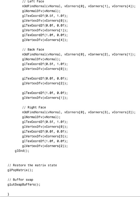
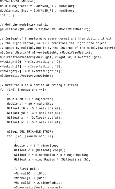
Listing 8.2. Source Code for the TOON Sample Program


Mipmapping
Mipmapping is a powerful texturing technique that can improve both the rendering performance and the visual quality of a scene. It does this by addressing two common problems with standard texture mapping. The first is an effect called scintillation (aliasing artifacts) that appears on the surface of objects rendered very small onscreen compared to the relative size of the texture applied. Scintillation can be seen as a sort of sparkling that occurs as the sampling area on a texture map moves disproportionately to its size on the screen. The negative effects of scintillation are most noticeable when the camera or the objects are in motion.
The second issue is more performance related, but is due to the same scenario that leads to scintillation. That is, a large amount of texture memory must be loaded and processed through filtering to display a small number of fragments onscreen. This causes texturing performance to suffer greatly as the size of the texture increases.
The solution to both of these problems is to simply use a smaller texture map. However, this solution then creates a new problem: When near the same object, it must be rendered larger, and a small texture map will then be stretched to the point of creating a hopelessly blurry or blocky textured object.
The solution to both of these issues is mipmapping. Mipmapping gets its name from the Latin phrase multum in parvo, which means “many things in a small place.” In essence, you load not a single image into the texture state, but a whole series of images from largest to smallest into a single “mipmapped” texture state. OpenGL then uses a new set of filter modes to choose the best-fitting texture or textures for the given geometry. At the cost of some extra memory (and possibly considerably more processing work), you can eliminate scintillation and the texture memory processing overhead for distant objects simultaneously, while maintaining higher resolution versions of the texture available when needed.
A mipmapped texture consists of a series of texture images, each one half the size of the previous image. This scenario is shown in Figure 8.10. Mipmap levels do not have to be square, but the halving of the dimensions continues until the last image is 1×1 texel. When one of the dimensions reaches 1, further divisions occur on the other dimension only. Using a square set of mipmaps requires about one-third more memory than not using mipmaps.
Figure 8.10. A series of mipmapped images.

Mipmap levels are loaded with glTexImage. Now the level parameter comes into play because it specifies which mip level the image data is for. The first level is 0, then 1, 2, and so on. If mipmapping is not being used, only level 0 is ever loaded. By default, to use mipmaps, all mip levels must be populated. You can, however, specifically set the base and maximum levels to be used with the GL_TEXTURE_BASE_LEVEL and GL_TEXTURE_MAX_LEVEL texture parameters. For example, if you want to specify that only mip levels 0 through 4 need to be loaded, you call glTexParameteri twice as shown here:
glTexParameteri(GL_TEXTURE_2D, GL_TEXTURE_BASE_LEVEL, 0);
glTexParameteri(GL_TEXTURE_2D, GL_TEXTURE_MAX_LEVEL, 4);
Although GL_TEXTURE_BASE_LEVEL and GL_TEXTURE_MAX_LEVEL control which mip levels are loaded, you can also specifically limit the range of loaded mip levels to be used by using the parameters GL_TEXTURE_MIN_LOD and GL_TEXTURE_MAX_LOD instead.
Mipmap Filtering
Mipmapping adds a new twist to the two basic texture filtering modes GL_NEAREST and GL_LINEAR by giving four permutations for mipmapped filtering modes. They are listed in Table 8.4.
Table 8.4. Mipmapped Texture Filters
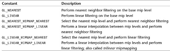
Just loading the mip levels with glTexImage does not by itself enable mipmapping. If the texture filter is set to GL_LINEAR or GL_NEAREST, only the base texture level is used, and any mip levels loaded are ignored. You must specify one of the mipmapped filters listed for the loaded mip levels to be used. The constants have the form GL_FILTER_MIPMAP_SELECTOR, where FILTER specifies the texture filter to be used on the mip level selected. The SELECTOR specifies how the mip level is selected; for example, GL_NEAREST selects the nearest matching mip level. Using GL_LINEAR for the selector creates a linear interpolation between the two nearest mip levels, which is again filtered by the chosen texture filter. Selecting one of the mipmapped filtering modes without loading the mip levels has the effect of disabling texture mapping.
Which filter you select varies depending on the application and the performance requirements at hand. GL_NEAREST_MIPMAP_NEAREST, for example, gives very good performance and low aliasing (scintillation) artifacts, but nearest neighbor filtering is often not visually pleasing. GL_LINEAR_MIPMAP_NEAREST is often used to speed up games because a higher quality linear filter is used, but a fast selection (nearest) is made between the different-sized mip levels available.
Using nearest as the mipmap selector (as in both examples in the preceding paragraph), however, can also leave an undesirable visual artifact. For oblique views, you can often see the transition from one mip level to another across a surface. It can be seen as a distortion line or a sharp transition from one level of detail to another. The GL_LINEAR_MIPMAP_LINEAR and GL_NEAREST_MIPMAP_LINEAR filters perform an additional interpolation between mip levels to eliminate this transition zone, but at the extra cost of substantially more processing overhead. The GL_LINEAR_MIPMAP_LINEAR filter is often referred to as trilinear mipmapping and until recently was the gold standard (highest fidelity) of texture filtering. More recently, anisotropic texture filtering (covered in the next chapter) has become widely available on OpenGL hardware but even further increases the cost (performance-wise) of texture mapping.
Generating Mip Levels
As mentioned previously, mipmapping requires approximately one-third more texture memory than just loading the base texture image. It also requires that all the smaller versions of the base texture image be available for loading. Sometimes this can be inconvenient because the lower resolution images may not necessarily be available to either the programmer or the end user of your software. The GLU library does include a function named gluScaleImage that you could use to repeatedly scale and load an image until all the needed mip levels are loaded. More frequently, however, an even more convenient function is available; it automatically creates the scaled images for you and loads them appropriately with glTexImage. This function, gluBuildMipmaps, comes in three flavors and supports one-, two-, and three-dimensional texture maps:
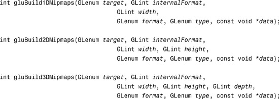
The use of these functions closely parallels the use of glTexImage, but they do not have a level parameter for specifying the mip level, nor do they provide any support for a texture border. You should also be aware that using these functions may not produce mip level images with the same quality you can obtain with other tools such as Photoshop. The GLU library uses a box filter to reduce images, which can lead to an undesirable loss of fine detail as the image shrinks.
With newer versions of the GLU library, you can also obtain a finer-grained control over which mip levels are loaded with these functions:

With these functions, level is the mip level specified by the data parameter. This texture data is used to build mip levels base through max.
Hardware Generation of Mipmaps
If you know beforehand that you want all mip levels loaded, you can also use OpenGL hardware acceleration to quickly generate all the necessary mip levels. You do so by setting the texture parameter GL_GENERATE_MIPMAP to GL_TRUE:
glTexParameteri(GL_TEXTURE_2D, GL_GENERATE_MIPMAP, GL_TRUE);
When this parameter is set, all calls to glTexImage or glTexSubImage that update the base texture map (mip level 0) automatically update all the lower mip levels. By making use of the graphics hardware, this feature is substantially faster than using gluBuildMipmaps. However, you should be aware that this feature was originally an extension and was promoted to the OpenGL core API only as of version 1.4. This is definitely the fastest and easiest way to build mipmaps on-the-fly.
LOD BIAS
When mipmapping is enabled, OpenGL uses a formula to determine which mip level should be selected based on the size of the mipmap levels and the onscreen area the geometry occupies. OpenGL does its best to make a close match between the mipmap level chosen and the texture’s representation onscreen. You can tell OpenGL to move its selection criteria back (lean toward larger mip levels) or forward (lean toward smaller mip levels). This can have the effect of increasing performance (using smaller mip levels) or increasing the sharpness of texture-mapped objects (using larger mip levels). This bias one way or the other is selected with the texture environment parameter GL_TEXTURE_LOD_BIAS, as shown here:
glTexEnvf(GL_TEXTURE_FILTER_CONTROL, GL_TEXTURE_LOD_BIAS, -1.5);
In this example, the texture level of detail is shifted slightly toward using higher levels of detail (smaller level parameters), resulting in sharper looking textures, at the expense of slightly more texture processing overhead.
Texture Objects
So far, you have seen how to load a texture and set texture parameters to affect how texture maps are applied to geometry. The texture image and parameters set with glTexParameter compose the texture state. Loading and maintaining the texture state occupies a considerable portion of many texture-heavy OpenGL applications (games in particular).
Especially time-consuming are function calls such as glTexImage, glTexSubImage, and gluBuildMipmaps. These functions move a large amount of memory around and possibly need to reformat the data to match some internal representation. Switching between textures or reloading a different texture image would ordinarily be a costly operation.
Texture objects allow you to load up more than one texture state at a time, including texture images, and switch between them very quickly. The texture state is maintained by the currently bound texture object, which is identified by an unsigned integer. You allocate a number of texture objects with the following function:
void glGenTextures(GLsizei n, GLuint *textures);
With this function, you specify the number of texture objects and a pointer to an array of unsigned integers that will be populated with the texture object identifiers. You can think of them as handles to different available texture states. To “bind” to one of these states, you call the following function:
void glBindTexture(GLenum target, GLuint texture);
The target parameter needs to specify GL_TEXTURE_1D, GL_TEXTURE_2D, or GL_TEXTURE_3D, and texture is the specific texture object to bind to. Hereafter, all texture loads and texture parameter settings affect only the currently bound texture object. To delete texture objects, you call the following function:
void glDeleteTextures(GLsizei n, GLuint *textures);
The arguments here have the same meaning as for glGenTextures. You do not need to generate and delete all your texture objects at the same time. Multiple calls to glGenTextures have very little overhead. Calling glDeleteTextures multiple times may incur some delay, but only because you are deallocating possibly large amounts of texture memory.
You can test texture object names (or handles) to see whether they are valid by using the following function:
GLboolean glIsTexture(GLuint texture);
This function returns GL_TRUE if the integer is a previously allocated texture object name or GL_FALSE if not.
Managing Multiple Textures
Generally, texture objects are used to load up several textures at program initialization and switch between them quickly during rendering. These texture objects are then deleted when the program shuts down. The TUNNEL sample program loads three textures at startup and then switches between them to render a tunnel. The tunnel has a brick wall pattern with different materials on the floor and ceiling. The output from TUNNEL is shown in Figure 8.11.
Figure 8.11. A tunnel rendered with three different textures.

The TUNNEL sample program also shows off mipmapping and the different mipmapped texture filtering modes. Pressing the up- and down-arrow keys moves the point of view back and forth in the tunnel, and the context menu (right-click menu) allows you to switch among six different filtering modes to see how they affect the rendered image. The abbreviated source code is provided in Listing 8.3.
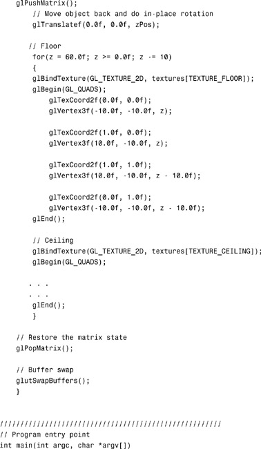
Listing 8.3. Source Code for the TUNNEL Sample Program


In this example, you first create identifiers for the three texture objects. The array textures will contain three integers, which will be addressed by using the macros TEXTURE_BRICK, TEXTURE_FLOOR, and TEXTURE_CEILING. For added flexibility, you also create a macro that defines the maximum number of textures that will be loaded and an array of character strings containing the names of the texture map files:
// Texture objects
#define TEXTURE_BRICK 0
#define TEXTURE_FLOOR 1
#define TEXTURE_CEILING 2
#define TEXTURE_COUNT 3
GLuint textures[TEXTURE_COUNT];
const char *szTextureFiles[TEXTURE_COUNT] =
{ "brick.tga", "floor.tga", "ceiling.tga" };
The texture objects are allocated in the SetupRC function:
glGenTextures(TEXTURE_COUNT, textures);
Then a simple loop binds to each texture object in turn and loads its texture state with the texture image and texturing parameters:
for(iLoop = 0; iLoop < TEXTURE_COUNT; iLoop++)
{
// Bind to next texture object
glBindTexture(GL_TEXTURE_2D, textures[iLoop]);
// Load texture, set filter and wrap modes
pBytes = gltLoadTGA(szTextureFiles[iLoop],&iWidth, &iHeight,
&iComponents, &eFormat);
gluBuild2DMipmaps(GL_TEXTURE_2D, iComponents, iWidth, iHeight, eFormat,
GL_UNSIGNED_BYTE, pBytes);
glTexParameteri(GL_TEXTURE_2D, GL_TEXTURE_MAG_FILTER, GL_LINEAR);
glTexParameteri(GL_TEXTURE_2D, GL_TEXTURE_MIN_FILTER,
GL_LINEAR_MIPMAP_LINEAR);
glTexParameteri(GL_TEXTURE_2D, GL_TEXTURE_WRAP_S, GL_CLAMP_TO_EDGE);
glTexParameteri(GL_TEXTURE_2D, GL_TEXTURE_WRAP_T, GL_CLAMP_TO_EDGE);
// Don't need original texture data any more
free(pBytes);
}
With each of the three texture objects initialized, you can easily switch between them during rendering to change textures:
glBindTexture(GL_TEXTURE_2D, textures[TEXTURE_FLOOR]);
glBegin(GL_QUADS);
glTexCoord2f(0.0f, 0.0f);
glVertex3f(-10.0f, -10.0f, z);
glTexCoord2f(1.0f, 0.0f);
glVertex3f(10.0f, -10.0f, z);
...
...
Finally, when the program is terminated, you only need to delete the texture objects for the final cleanup:
///////////////////////////////////////////////////
// Shut down the rendering context. Just deletes the
// texture objects
void ShutdownRC(void)
{
glDeleteTextures(TEXTURE_COUNT, textures);
}
Also, note that when the mipmapped texture filter is set in the TUNNEL sample program, it is selected only for the minification filter:
glTexParameteri(GL_TEXTURE_2D, GL_TEXTURE_MAG_FILTER, GL_LINEAR);
glTexParameteri(GL_TEXTURE_2D, GL_TEXTURE_MIN_FILTER, GL_LINEAR_MIPMAP_LINEAR);
This is typically the case because after OpenGL selects the largest available mip level, no larger levels are available to select from. Essentially, this is to say that after a certain threshold is passed, the largest available texture image is used and there are no additional mipmap levels to choose from.
Resident Textures
Most OpenGL implementations support a limited amount of high-performance texture memory. Textures located in this memory are accessed very quickly, and performance is high. Initially, any loaded texture is stored in this memory; however, only a limited amount of memory is typically available, and at some point textures may need to be stored in slower memory. As is often the case, this slower memory may even be located outside the OpenGL hardware (such as in a PC’s system memory as opposed to being stored on the graphics card or in AGP memory).
To optimize rendering performance, OpenGL automatically moves frequently accessed textures into this high-performance memory. Textures in this high-performance memory are called resident textures. To determine whether a bound texture is resident, you can call glGetTexParameter and find the value associated with GL_TEXTURE_RESIDENT. Testing a group of textures to see whether they are resident may be more useful, and you can perform this test using the following function:
GLboolean glAreTexturesResident(GLsizei n, const GLuint *textures,
GLboolean *residences);
This function takes the number of texture objects to check, an array of the texture object names, and finally an array of Boolean flags set to GL_TRUE or GL_FALSE to indicate the status of each texture object. If all the textures are resident, the array is left unchanged, and the function returns GL_TRUE. This feature is meant to save the time of having to check through an entire array to see whether all the textures are resident.
Texture Priorities
By default, most OpenGL implementations use a Most Frequently Used (MFU) algorithm to decide which textures can stay resident. However, if several smaller textures are used only slightly more frequently than, say, a much larger texture, texturing performance can suffer considerably. You can provide hints to whatever mechanism an implementation uses to decide texture residency by setting each texture’s priority with this function:
void glPrioritizeTextures(GLsizei n, const GLuint *textures,
const GLclampf *priorities);
This function takes an array of texture object names and a corresponding array of texture object priorities that are clamped between 0 and 1.0. A low priority tells the implementation that this texture object should be left out of resident memory whenever space becomes tight. A higher priority (such as 1.0) tells the implementation that you want that texture object to remain resident if possible, even if the texture seems to be used infrequently.
Bear in mind that texture priorities are only a hint to the implementation. Some OpenGL implementations are known to ignore them completely.
Summary
In this chapter, we extended the simple image loading and display methods from the preceding chapter to applying images as texture maps to real three-dimensional geometry. You learned how to load a texture map and use texture coordinates to map the image to the vertices of geometry. You also learned the different ways in which texture images can be filtered and blended with the geometry color values and how to use mipmaps to improve both performance and visual fidelity. Finally, we discussed how to manage multiple textures and switch between them quickly and easily, and how to tell OpenGL which textures should have priority if any high-performance (or local) texture memory is available.