
Chapter 10
Color Management

Photograph by David Kelbe, Imaging Science student, Rochester Institute of Technology.
What Is CM?
Color Management (CM) has been going on for as long as color printing paper and color slide film have been available. For instance, a photographer would find a particular batch of emulsion printed a bit on the magenta side and would adjust the printing color balance until that batch of emulsion was finished. CM accomplishes the same thing, however the problem has gotten much more complicated.
In photography today, your digital camera may communicate with your monitor or your printer directly. Creating an image on your computer means your monitor has to communicate with your printer. This seems like a manageable problem as illustrated in Figure 10-1. The relationships between the camera and the monitor, the monitor and the printer, and the camera and the printer have to be defined. This is a system with only three possible relationships.
In the world of digital photography, it is rare that these are the only three devices involved. Perhaps you send an image to a customer electronically. That customer then shares the image with their staff. Your camera now needs to communicate with monitors that you have never seen. That same customer then prints the image on a local printer in their office and sends it to the production department to be printed on a large-format printer. The same digital image could look different when it is viewed on different monitors or printed to different printers. The problem now becomes bigger, as illustrated in Figure 10-2. Color management is the solution to this problem.

Figure 10-1 Managing color in a system.

Figure 10-2 The problem of defining a relationship between multiple devices.
The International Color Consortium (ICC) is the governing body for color management.
What Is Color Management?
In the world of digital imaging systems, color management is the conversion between the representations of color on different devices. These devices can include digital cameras, image scanners, monitors, LCD and plasma television screens, printers, offset presses, and projectors. The goal of color management is to assist in achieving the same appearance of an image on all of these devices. This of course depends on the ability of the devices to produce similar color gamuts. When they can't, color management assists in producing the best compromise of color representation. This is achieved through the use of ICC profiles. ICC profiles are created using a standard common format so that devices made by different manufacturers are compatible with each other.
Who Governs Color Management?
Before going further, we should discuss the background of color management and who governs the standard. The International Color Consortium1 (ICC) is the governing body in the field of color management. The ICC was founded in 1993 and is the group that oversees the field of color management and maintains the ICC profile specification. The ICC's mission is to promote the use and the adoption of open, vendor-neutral, cross-platform color management systems.
The nine founding members of the ICC were: Adobe Systems Incorporated, Agfa-Gevaert N.V., Apple Computer, Inc., Eastman Kodak Company, FOGRA-Institute, Microsoft Corporation, Silicon Graphics Inc., Sun Microsystems, Inc., and Taligent, Inc. Today there are now approximately seventy members across the photographic and printing industry. There are also six honorary members, including Rochester Institute of Technology, home to the Munsell Color Science Laboratory.
For color management to be successful these industry giants realized that there was a need for all devices and software created by different companies to be able to communicate with each other. To accomplish this, they combined to develop the framework for a color management system that utilized ICC profiles developed to a standard format. The current version of the standard is Specification ICC.1:2004:10 and can be found at www.color.org.
Chromaticity Diagram and Chromaticity Values
Before going further, we need to explain a few of the tools needed to understand CM. Most tools used to examine the contents of an ICC profile will use a chromaticity diagram to display a color gamut. See Figure 10-3. The chroma-ticity diagram was developed by the CIE (International Commission on Illumination). In 1931, the CIE defined a color space referred to as CIE XYZ. The XYZ values are called tristimulus values and represent three imaginary primaries. These values are determined by integrating the spectral power distribution of the light source, the spectral response of the sample, and the spectral response of the human visual system. See Appendix D. The difficulty when working with tristimulus values is that they cannot be visualized, meaning if you are provided with an X, Y, and Z tristimulus value and asked what color it represents, it would be a very difficult if not impossible task for most to accomplish.

Figure 10-3 Chromaticity diagram.
Realizing this, the CIE has also defined a method to transform tristimulus values into chromaticity coordinates that can be plotted on a chromaticity diagram. These values are xyY. The Y is a luminance value and is not plotted. The chromaticity coordinates x and y are calculated according to Equations 10-1 and 10-2 below.
These chromaticity coordinates allow hue and saturation to be plotted on a chromaticity diagram independent of luminance (see Figure 10-3). Pure colors plot along the outside of the horseshoe shaped diagram referred to as the spectral or monochromatic locus. The numbers in blue indicate the wavelength of light in nanometers. The chromaticity diagram is used in color management to illustrate color gamuts and white points.
Color Gamut
A color gamut is the set of colors that a device can produce.
A color gamut can be defined as the set of colors that a device can reproduce. Human vision has the largest color gamut. Unfortunately there is not a device available that can reproduce every color that we can see. Color gamuts are usually represented on the chromaticity diagram as shown in Figure 10-3. The chromaticity coordinates of the pure red, green, and blue are calculated and plotted. Lines are drawn connecting the three points. Any color that falls in the interior of the triangle can be reproduced; any color that is outside the triangle cannot be reproduced and is referred to as an out-of-gamut color.
An out-of-gamut color cannot be accurately reproduced and must be remapped to an in-gamut color.
This is one of the problems that has to be addressed by color management. For example, when the color gamut of the monitor is larger than the color gamut of the printer, how are the out-of-gamut colors going to be printed? This is handled by use of rendering intents in CM.
Rendering Intents
The ICC specifies four different rendering intents; perceptual, saturation, relative colorimetric, and absolute colorimetric. These will be discussed later. Rendering intents are the methods the CM software engine uses to handle out-of-gamut colors. Referring to Figure 10-3, out-of-gamut colors would be those colors that exist in the Device 1 color gamut but not in the Device 2 color gamut.
There are two basic methods for handling out-of-gamut colors. The first is gamut clipping. In this method, every out-of-gamut color is mapped to the closest color that is in gamut. See Figure 10-4. In this case, several different input colors can be mapped to the same output color. This can cause a loss of tonal variation in highly color-saturated areas.
The second method is gamut compression. In this method, the larger input gamut is compressed to fit inside of the smaller output color gamut. However, to accomplish this, the smaller gamut is first compressed to make room for the larger gamut.
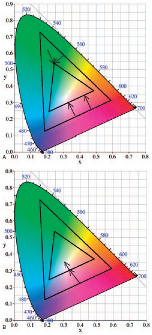
Figure 10-4 Illustration of (A) gamut clipping and (B) gamut compression.
In this method, some colors that were perfectly reproduced prior to the compression will be changed after compression. This can also lead to loss of some tonal variation in highly color-saturated areas.
Rendering Intents
As mentioned earlier, there are four rendering intents: perceptual, saturation, relative colorimetric, and absolute colorimetric. Each has its own specific characteristics and applications.
The perceptual rendering intent is mainly used for pictorial images. This rendering intent tries to preserve luminance or brightness over saturation and hue information. This is done because an observer is more likely to notice changes in brightness over subtle changes in hue. The perceptual rendering intent is the only one that uses gamut compression to handle gamut mapping; the remaining three use gamut clipping.
The saturation rending intents primary use is with graphics, such as company logos or pie charts. With these types of images, it is believed that bright colors that grab the attention are best. The saturation rendering intent will put emphasis on mapping out-ofgamut colors to a nearby color that is highly saturated. This may result in a color shift from the original image to the reproduction. However, human color memory is poor. We will often remember the sunset on a beach as being much more colorful that it was. Keeping this in mind, there are times when the saturation intent, which favors brilliant colors, will produce very pleasing color photographic images.
The absolute rendering intent is used when strict color conversions are necessary and is usually used when you want to proof what the final product will look like. For example, an image needs to be proofed for reproduction in a magazine. The printer we have to work with is a photographic-quality printer that uses a bright white paper. The paper used in the magazine is of lesser quality and has a white point that is darker than the photographic paper. The absolute-rendering intent can be used to map the white of the photographic paper to the white of the magazine paper. All the remaining colors are then mapped accordingly. This allows for proofing of the final product to be done without having to print it on the magazine paper.
The last rendering intent is relative colorimetric. In this intent, the white point of the source is mapped to the white point of the destination. This is referred to as white point compensation. All the remaining colors are shifted accordingly. The resulting image may be slightly brighter or darker than the original, but the whites will match. This intent will also often work well with photographs.
Calibration vs. Characterization
The terms calibration and characterization are often used interchangeably in photography and CM. They do not mean the same thing.
Calibration is a process of returning a device to a known standard. For example, if you have a scale that is no longer reading 0 pounds when there is nothing on it, the scale can be adjusted back to zero or calibrated. In the world of digital photography, if a printer, monitor, or scanner can be adjusted back to a known standard, then it can be calibrated.
The four rendering intents in CM are perceptual, saturation, absolute, and colorimetric.
Characterization is the process of determining how a device is performing. This would include what its capabilities and limitations are. As an example, we can characterize the performance of a camera. This can be done by testing the camera for a linear response, determining its spectral response, determining the noise level present, and determining the range of illuminances it can record. Characterization describes the behavior of the device. These characteristics are used to set the standard for calibration. When something in a device's characteristics change a new standard for calibration may have to be developed. The need to re-characterize a device usually becomes apparent when the device can no longer be calibrated, which often indicates its characteristics have changed.
All the parts of a digital system— the camera, monitor, scanner, printer, and any hardware used in the CM process—are described in mathematical terms that a computer can then use. This allows us to characterize all of these devices. The term used for this characterization is a profile or more specially an ICC profile.
Color Spaces
There are two types of color spaces: device-dependent and device-independent color spaces. A device-dependent color space is tied to the behavior of a specific device such as a camera or monitor. Every device defines its own device-dependent color space. For example, the color space of a monitor is defined by a finite set of RGB values that are used to control the monitor's output, or a CMYK printer's color space depends on the finite combination of the CMYK dyes that can be used to create a print.

Figure 10-5 A graphical representation of color management.
A device-independent color space, on the other hand, uses numerical values to model human vision. There are many such color spaces, but in CM there are two that are used—the CIE XYZ space and the CIE LAB space discussed in Chapter 9. These two color spaces are used in CM and the profile connection space.
What Is an ICC Profile?
An ICC profile is used to describe or define the relationship between a device-dependent color space, such at the RGB values of a monitor to the corresponding values in a deviceindependent color space such as CIELAB. Profiles follow the standard crossplatform format defined by the ICC so that they can be used with any software or hardware that follows the standard.
Profiles can be device-specific such that they describe a single device, such as a camera or scanner. Profiles can also be abstract so that they describe a color space such as CIELAB.
Profile Connection Space
Bringing all this information together is the profile connection space or PCS. The PCS takes Figure 10-2 and simplifies the process as shown in Figure 10-5. Now the user no longer has to define the relationship between all possible devices. Instead, a profile is developed that defines the relationship between a device and the PCS. For example, a camera profile would define the relationship between the RGB digital counts in the camera to the PCS, or a printer profile would define the relationship between the PCS and the CMYK values required for the printer. Both of these are oneway profiles. There are profiles such as a monitor profile that define both the relationship from RGB pixel values to the PCS and also the reverse. Therefore, by defining the relationship between a device and the PCS any two devices can now easily communicate through the use of ICC profiles.
Profile Classes
There are several classes of profiles designed for specific reasons.
- Input profiles describe scanners and digital cameras. This type of profile is a one-way profile. It can only take input and convert it to PSC space. You cannot output data to a scanner or camera so there is no need for these profiles to provide a two-way path.
- Display profiles describe monitors and display devices. A display profile is a two-way profile because a display device can act as both an input device and an output device. You can create an image on your monitor and want to reproduce it on your printer. Here the monitor is acting as an input device. On the other hand, if you display an image from a camera onto a monitor, it is now acting as an output device. For example, a two-way profile can take an image from a monitor and move it to the PCS or it can take an image in the PCS and display it to the monitor.
- Output profiles describe printers and presses. An output profile is also a one-way profile because it only needs to take an image from the PCS and send it to the output device.
Building a Profile
Many devices, such as cameras and printers, come with profiles provided by the manufacturer often referred to as “canned profiles". These profiles have been created for the “average" device. For example, the profile that comes with an inkjet printer is the profile that was developed based the average performance for that printer. In many cases, this will work fine, however there are times when it may be necessary to create a unique profile for that printer. For example, a canned profile for an Epson printer will have been developed using Epson inks in the printer. If you use inks made by another manufacturer the canned profile may no longer produce satisfactory results. There are many products available to accomplish this that range in price from the very affordable to the very expensive.

Figure 10-6 IT8 target used for ICC profile creation.
All of these products come with software that steps the user through creating an ICC profile. The user will be prompted to set the necessary parameters for the creation of the profile, such as the device type with options including a scanner, printer, camera, or projector among others. The type of target being used, such as the IT8 target shown in Figure 10-6, must be designated. These are available in reflection and transmission versions. A reference file is always provided with these targets, which provides the software with the color information it is trying to match. If the profile is for a display device such as an LCD or projector, the desired white point and gamma must also be selected.
When all the set-up parameters have been determined, the color patches that are printed or displayed must be measured. This is usually done with a colorimeter or a spectroradiometer. The data is then provided to the software, which then creates the profile.
Using an ICC profile
ICC profiles are applied in several manners. Many cameras will embed the camera default profile in the output image file. This can be removed using image editing software if necessary. Most ICC profiles are applied within image editing software while preparing the image for printing.
REVIEW QUESTIONS
- Who developed and governs the standard for ICC profiles?
- American National Standards Institute
- International Commission on Illumination
- International Color Consortium
- What is the goal of color management?
- to make all devices have the same color gamut
- to assist in achieving the same appearance of an image on all devices
- to have all devices use the same ICC profile
- In most color management software, color gamut's are displayed on a
- chromaticity diagram
- on a CIELAB plot
- on a polar coordinate plot
- Chromaticity coordinates are calculated from
- CIELAB values
- RGB pixel values
- tristimulus values
- CMYK values
- A color that falls outside of a devices color gamut is referred to as
- an out-of-gamut color
- as a dark color
- as color with high saturation
- How many rendering intents are used in color management?
- 2
- 3
- 4
- 5
- Which rendering intent using gamut-compression to handle out-of-gamut colors?
- perceptual rendering intent
- saturation rendering intent
- absolute rendering intent
- relative colorimetric rendering intent
- A digital camera would require what type of profile?
- input profile
- display profile
- output profile