
Chapter 6
Tone Reproduction
Photograph by Robert Weber, student, Rochester Institute of Technology
Purposes of Tone Reproduction
Except where the photographer is creating a photograph that bears no resemblance to an original subject, it is important to study the relationship between the tones in the original scene and the corresponding tones in the reproduction. Thus, by studying the factors influencing the reproduction of tone, the photographer can learn how to control the process to give the desired results.
Chapter 4 showed how the tone-recording properties of films and papers can be described through the use of the characteristic curve. If the conditions of measurement used to obtain the data simulate the conditions of use, the characteristic curve provides an excellent description of the tone-rendering properties of the film or paper emulsion. However, the result of the photographic process is a reproduction that will be observed by a person, which therefore involves the characteristics of the human visual system. In this respect, perceptual phenomena, including brightness adaptation, appear to play a significant role. Thus, determining the objective tone-reproduction properties required in a photograph of excellent quality is related to the perceptual conditions at work when the image is viewed. The final image that is viewed normally includes the cumulative tone-repro-duction characteristics of the film or digital sensor plus the camera optics and the printing material plus the printing optics, inkjet, or laser printer characteristics or, in the case of slides and motion-picture films, the projector optical system.
Objective and Subjective Tone Reproduction
When determining the tone-reproduction properties of the photographic system, objective and subjective aspects are considered. In the objective phase, measurements of light reflected from the subject are compared to measurements of light reflected or transmitted by the photographic reproduction or light emitted from a display. These reflected-light readings from the subject are called luminances and can be measured accurately with a photoelectric meter having a relative spectral response equivalent to that of the “average" human eye. The logarithms of these luminances are then plotted against the corresponding reflection or transmission densities in the photographic reproduction, and the resulting plot is identified as the objective tone-reproduction curve.
Luminance is light per unit area, an objective concept. Lightness is a subjective perception that correlates only roughly with luminance.
The contrast of a photographic print will appear lower when viewed against a dark surround than when viewed with a light surround.
The perception of the lightness of a subject or image area corresponds roughly to its luminance but, unlike luminance, lightness is not directly measurable. Because the perception of lightness involves physiological as well as psychological factors, an area of constant luminance can appear to change in lightness for various reasons, including whether the viewer had previously been adapted to a high or a low light level. Psychological scaling procedures have been devised to determine the effect of viewing conditions on the perception of lightness and contrast. It has been established, for example, that a photograph appears lighter when viewed against a dark background than when viewed against a light background; and that the contrast of a photograph appears lower when viewed with a dark surround than when viewed with a light surround.
A graph showing the relationship between the perceived lightnesses of various areas of a scene or photograph and the measured luminances of the corresponding areas would be called a subjective tone-reproduction curve. It is because the perception of a photograph’s tonal qualities can vary with the viewing conditions, that the American National Standards Institute and other organizations have prepared standards for the viewing conditions in which photographs are produced, judged, and displayed. The influence of viewing conditions should not be underestimated when considering the specifications for optimum tone reproduction.
Objective Tone Reproduction/Preferred Photographs
Most photographers realize that tone-reproduction characteristics required for satisfactory photographs depend to a great extent upon the lighting conditions under which the photographs are viewed. Unfortunately, reflection-type prints are commonly viewed under illumination levels ranging from less than 100 lux to more than 5,000 lux. (The Photographic Society of America currently recommends an illuminance of 800 lux for judging and displaying reflection prints [PSA Uniform Practice No. 1, 1981].) Large transparencies are usually viewed with back illumination, with a recommended illuminance of approximately 1,400 candelas per square foot.
However, since these transparencies are viewed under the same general room illumination as reflection-type prints, the eye is in a similar state of adaptation. Slides and motion-picture films projected onto a screen and observed in a darkened room are viewed with the eye in a considerably different state of adaptation. As there are three widely varying viewing conditions, different objective tone-reproduction curves are required if the photographs are to meet the subjective standards of excellence in each case.
In order to determine the objective tone-reproduction curve that gives the best subjective tone reproduction for black-and-white reflection prints, an experiment was performed under the conditions typically encountered by photographers. Various outdoor scenes were photographed at different exposure levels. The exposed films were processed to different contrasts, and from the resulting negatives black-and-white prints were produced. The prints varied in contrast, density, and tone-reproduc-tion properties. Numerous observers were asked to view these prints and judge them for their subjective quality. The objective tone-reproduction curves for all of the first-choice prints were averaged, and the resulting curve is illustrated in Figure 6-1, where the reflection densities of the print are plotted against the log luminances of the scene.
The 45° reference line is arbitrarily located so that its lowest point corresponds to a diffuse white object in the scene and the minimum density of the photographic print material. If the luminances in the scene were reproduced exactly in the print, the resulting tone-reproduction curve would have a slope of 1.00, matching that of the reference line. In fact, the average curve for first-choice prints is located 0.2 to

Figure 6-1 Objective tone-reproduction curve for a preferred reflection print of an average outdoor scene.
0.3 density units below the 45° line except in the highlight region, where the curve cannot go below the minimum density of the paper. The curve shows low slope in both the highlight and shadow regions, but has a gradient of 1.1 to 1.2 in the midtone area. This indicates that the print’s highlights and shadow regions are compressed compared to the original scene, while the mid-tones have been slightly expanded in contrast. The experiments that lead to this tone-reproduction curve involved scenes of low and high contrast, as well as interior and exterior subject matter. The results in all cases were remarkably similar to that shown in Figure 6-1. Whenever the departure from the desired slopes was greater than 0.05, the observers invariably judged the prints as being unacceptable in contrast, indicating very narrow tolerance levels. Consequently, it appears that the desired objective tone-reproduction properties in a black-and-white reflection print are essentially

Figure 6-2 Objective tone-reproduction curve for a transparency of preferred quality, viewed on a bright illuminator under average room light.
independent of the characteristics of the original subject.
The tone-reproduction curve for facsimile reproduction would be a 45° straight line.
A projected image in a darkened room that had the same luminances as a good-quality reflection print would appear to be unacceptably flat.
Similar studies have been performed with large transparencies viewed under room light conditions on a back illuminator. The objective tone-reproduc-tion curve that gave the best objective tone reproduction for this condition is illustrated in Figure 6-2, where the diffuse transmission density of the image is plotted against the log luminance of the scene. The desired objective tone-reproduction curve is very nearly the same as the 45° reference line but with a midtone slope still greater than 1.0.
The differences in curve shape between the transparency and the reflection print are due primarily to the increased density range of which the transparency film is capable, since the eye is in a similar state of adaptation. As the brightness of the illuminator used to view the transparency increases, the desired tone-reproduction curve moves slightly above and to the right of the one illustrated in Figure 6-2.
The preferred objective tone-reproduction curve for a transparency or a motion picture projected onto a screen and viewed in a darkened room is illustrated in Figure 6-3, where the effective screen viewing densities (measurements made with a spot photometer of the projected image on the screen) are plotted against the log luminances of the scene. This curve shows a slope considerably greater than that of the previous two and is principally the result of the dark-adaptation, lateral-adaptation, and visual-flare characteristics of the eye. Psychophysical experiments of the human eye’s response indicate that the perceived brightness (lightness) contrast is lower when the eye is dark adapted than when it is light adapted.
Since it is desirable to obtain a subjective lightness contrast in the

Figure 6-3 Objective tone-reproduction curve for motion pictures (and slides) of preferred quality, projected on a screen in a darkened room.
projected image on the screen similar to what would occur in a reflection print, the objective tone-reproduction curve necessary for dark-adapted conditions must have a greater slope. If a higher-intensity lamp is used in the projector, the tone-reproduction curve shifts slightly to the right and above that shown in a Figure 6-3. Therefore, the preferred density level and optimum

Figure 6-4 Flow diagram of the photographic process.
exposure for a transparency film are related to the amount of light supplied by the projector and screen used when viewing the images. This means that the effective film speed for a reversal film is in part related to the conditions under which the images will be viewed.
The three conditions illustrated represent those most commonly encountered in photographic reproductions and pertain only to pictorial representations. In each case, the (objective) curve represents optimum subjective tone reproduction, and thus an aim for the system. It is the task of the photographer to select the appropriate materials and processes to achieve these aims.
Objective Tone Reproduction Analysis
The flow diagram in Figure 6-4 isolates some of the more important factors to be considered in a study of the photographic reproduction of tones. Since the subject represents input in terms of log luminance values and the print represents output in terms of densities, it is the stages in between that must concern us. It should be noted that a study of tone-reproduction characteristics excludes many important properties of the photographic system. For example, no attention is paid to the reproduction of small detail or to the reproduction of various colors in the scene. Thus, when considering the various stages of the process, only those factors that influence the large-scale tonal relationship should be considered
Densities, which are used to measure image tones, are logarithms; therefore it is appropriate to express the measurements of subject tones as log luminances for tone-reproduction graphs.
To simplify this task it is necessary to consider only three principal stages in the process, as illustrated in Figure 6-5. Each of these stages will be represented by a graph illustrating its influence on the tonal relationships. Each graph has a set of input values and a set of output values. The output from the first stage becomes the input to the second, and so on through the system, thus forming a chain of input/output relationships. In this fashion, the major stages of the process can be studied for their effects upon the end result. The important phases of the photographic process can be synthesized by means of this tone-reproduction study. For such an approach to work, data must be obtained about these phases. Methods for obtaining data about the

Figure 6-5 Simplified tone-reproduction system.
subject, film, and photographic papers were discussed in Chapter 3 and so will not be repeated here. However, the problem of optical flare was only briefly mentioned in Chapter 2, and so a discussion of it follows.
Optical Flare
When a camera is aimed at a subject, the subject luminances and, therefore, the physical values of light reaching the lens represent the initial input data for the process. If the luminance of the lightest diffuse highlight is divided by the luminance of the darkest shadow with detail, the resulting value is termed the luminance ratio, and the log of that ratio is termed the log luminance range. In an important experiment conducted by Jones and Condit of the Eastman Kodak Research Laboratory, the luminance ratios of more than 100 outdoor scenes were measured. The frequency distribution of the luminance ratios is shown in Figure 6-6. The smallest ratio encountered was 27:1 and the largest was 760:1, with an average ratio of 160:1. The frequency distribution in Figure 6-6 indicates that luminance ratios of less than 100:1 and greater than 300:1 are encountered much less often.

Figure 6-6 Frequency distribution of luminance ratios of outdoor scenes.
Much less information exists about the luminance ratios of interior scenes, but some experiments indicate that the average luminance ratio of an interior scene is not greatly different from 160:1. The average scene ratio of 160:1 has special significance since most manufacturers optimize exposure and development conditions for their products based on this value. A set of luminance readings from a typical outdoor scene is shown in Table 6-1. Nine different areas of the scene were measured with a spot meter to obtain the data. The luminance ratio of the scene is 160:1.
When the camera is pointed at such a scene, the lens receives the light from each area and focuses it on the film plane at the back of the camera. Thus, in this first stage of tone reproduction, the subject luminances are transformed to image illuminances at the image plane. In an ideal situation there would be a direct proportion between the subject luminances and the image illuminances and the tonal relationships would be maintained at the back of the camera. However, at any point in the image plane of a camera, the illuminance is the result of two different sources: (a) the illumination focused by the lens and projected to the image plane, which constitutes the image-forming light, and (b) light that is the result of single and multiple reflections from the lens surfaces, diaphragm, shutter blades, and additional interior surfaces of the camera, providing an approximately uniform illuminance over the whole image area.
Table 6-1 Luminance values of an outdoor scene
| Luminance | |||
| Area No. | Description of Area | Candela/Square Foot | Foot lambert |
| 1 | White cloud | 1,114 | 3,500 |
| 2 | Clear sky | 637 | 2,000 |
| 3 | Grass in sunlight | 350 | 1,100 |
| 4 | Side of house in sunlight | 200 | 630 |
| 5 | Front of house | 115 | 360 |
| 6 | Car in open shade | 67 | 210 |
| 7 | Tree trunk | 38 | 120 |
| 8 | Grass in shade | 22 | 70 |
| 9 | Base of tree in heavy shade | 7 | 22 |
Luminance ratio of subject = 160:1
The luminance ratio of average outdoor and indoor scenes is considered to be approximately 160:1.
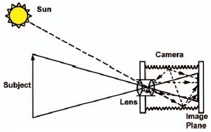
Figure 6-7 The occurrence of flare in a camera. Solid lines in camera represent image-forming light, while dashed lines in camera represent non-image-forming (flare) light.
This second source of light is referred to as flare light, or simply flare, and provides non-image-forming light, since it is not directly focused by the lens. Figure 6-7 illustrates how flare occurs in a simple camera. Flare light is present on any projected image, whether it is formed by the lens or a pinhole, because the projected light is reflected off any interior surface.
Since flare is non-image-forming light and occurs in the image plane as a uniform veil, it increases the illuminance of every point on the camera image and thus results in a loss of image contrast. The effect is similar to viewing a projected transparency on a screen in a darkened room and then viewing the same image with the room lights on. The loss of image contrast on the screen is due to the additional illuminance on the screen surface produced by the room lights.
To illustrate the effect in the camera, assume that the camera is being pointed at an average subject with a 160:1 luminance ratio. If there were no flare light in the camera, the range of image illuminances at the back of the camera would also be 160:1. However, if in addition to that image-forming light there was one unit of flare light uniformly distributed over the film plane (that is, the corners are receiving one unit, the edges are receiving one unit, the center is receiving one unit), the ratio would now be 161:2, which reduces to approximately 80:1. Thus the 160:1 luminance ratio in front of the camera has been reduced to an illuminance ratio of 80:1 at the back of the camera.
It is perhaps obvious that the reduction in contrast is the result of different percentage increases at the opposite ends of the scale. For example, the additional unit of flare light in the shadows provides a doubling of the light in that region, while the additional unit of light in the highlights represents only a very small percentage of increase in that region. The result is that the ratio of illuminances at the back of the camera is always less than the ratio of luminances in the subject. Flare can be expressed as a flare factor (Eq. 6-1), which is derived by dividing the luminance ratio in front of the camera by the illuminance ratio at the back of the camera:
The flare factor will be 1.0 when there is no flare light, which would occur only in a contact-printing situation. The results of many experiments indicate that most modern lenses and cameras have an average flare factor of nearly 2.5 under typical conditions. Under some conditions, the flare factor may be as high as 4 or 8, or as low as 1.5.
Some of the more important factors that influence the amount of flare are:
1.Subject characteristics. Subjects with high luminance ratios or subjects with large areas of high luminance tend to produce large amounts of flare. Snow scenes, beach scenes, and high-key scenes (white on white) are all examples of subject matter that would give large amounts of flare.
2.Lighting conditions. Subjects that are backlit (with the light source in the field of view) give greater amounts of flare than subjects that are frontlit.
3.Lens design. Designing a lens to contain the smallest number of elements possible and coating the elements with antireflection materials will greatly minimize flare. However, lens design and coatings cannot decrease the flare factor to 1.00 (zero flare), since considerable stray light still reaches the image plane by reflection from the lens mount and other inner areas of the camera, and even the surface of the film itself.
4.Camera design. If the camera’s interior is black and the surfaces are matte, stray light reflections will be minimized. Any light leaks in the camera body will also act as flare and further reduce the image contrast.
5.Dust and dirt. By keeping the lens surfaces clean and minimizing dust particles in the camera body, the number of surface areas on which light reflections may occur can be minimized and the flare reduced.
Of all the factors listed, the two with the greatest influence on flare are the subject characteristics and the lighting conditions. A number of studies suggest that approximately 80% of the flare encountered in typical photographic situations is governed by these two factors. Consequently, even when high-quality lenses and cameras are used and kept in good condition, the photographer cannot avoid the loss of image contrast that results from flare. Thus, it is important for the photographer to obtain an estimate of the amount of flare, in the form of a flare factor that is affecting the camera system.
The direct method for measuring flare involves the use of a gray scale and a small spot meter. The camera is focused on the gray scale and the small spot meter is used to measure the corresponding image areas at the back of the camera. The ratio of luminances on the original gray scale can then be compared to the ratio of illuminances at the back of the camera, and the flare factor can be computed. Although this method is direct, it is a difficult procedure to follow.
An alternative method for a film camera is to work backwards using a photographic film as the measuring device. First, a negative of the gray scale is made with the camera. A second piece of film is exposed in a sensitometer, which is a flare-free instrument since it involves a contact print. Both pieces of film are processed together to ensure identical development and the resulting characteristic curves are drawn. The highlight densities of the curves are matched, and any difference in the rest of the curves can be attributed to flare. The actual amount of flare can be found by measuring the horizontal displacements between the two curves, at the bottom of the top curve. The antilog of the difference in log exposures is the flare factor. There is currently no alternative method similar to this for a digital camera.
Such a set of curves is illustrated in Figure 6-8, which shows that the effect of flare on the characteristic curve is to increase the length of the toe, add curvature to the lower part of the straight line, and reduce the shadow contrast (slope) in the negative. The greater the amount of flare in the system, the greater the differences will be between these two curves.
Camera flare reduces contrast mostly in the shadow areas. Enlarger flare reduces contrast mostly in the highlight areas.
A typical camera flare factor of 2.5 reduces a scene luminance ratio of 160:1 to 64:1, and in small-format cameras it is a practical impossibility.
The purpose for obtaining the flare factor is to estimate the range of illuminances that will occur at the back

Figure 6-8 The effects of flare on the characteristic curve of a black-and-white negative material. Curve A was generated by photographing a reflection gray scale with a camera, while curve B came from a sensitometer (contact printed to a step tablet.)
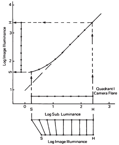
Figure 6-9 The effect of optical flare (or other stray light) on the image illuminances at the back of the camera.
of the camera, and thus the range of tones to which the film or sensor will be exposed. For example, if a scene with a luminance ratio of 200:1 is photographed with a lens-camera combination with a flare factor of 4, the film or sensor will actually receive a ratio of illuminances of 200 divided by 4, which equals 50:1. For film, the exposure ratio (or, more usefully, the log-exposure range) and ultimately the development time necessary to produce a normal-contrast negative, can be determined. In a digital system, the contrast would be adjusted using image editing software such as Photoshop. There are several options such as the Levels, Curves, or Contrast command that can be used.
In order to study more thoroughly the influence of flare in the tone-reproduction cycle, consider the graph in Figure 6-9. The data for such a graph are derived from the flare-measurement method first described. A small spot photometer was used to meter the illuminances provided by the gray scale at the back of a camera, and the relationships between subject luminance and image illuminance were plotted. Logarithms are commonly used to describe the input and output properties of light-sensitive photographic materials. For this reason the scales are log luminance and log illuminance on the graph. If there were no flare in the system, the relationship between subject log luminance and image log illuminance would be a 45° straight line, indicating a direct proportion.
However, as discussed earlier, the low-illuminance shadow regions at the back of the camera suffer a greater percentage increase than do the highlight illuminances. Since the highlights are relatively unaffected, the relationship is at a slope of 1.0 (45°) in that area. As the image illuminances decrease (the shadows become darker), the percentage increase becomes greater and thus reduces the slope of the curve considerably, resulting in a loss of contrast in the shadow area. This indicates that flare reduces shadow contrast in addition to reducing the overall ratio of tones at the film plane.
In Figure 6-9, the nine dots on the log luminance axis represent the nine luminances of a typical outdoor scene listed in Table 6-1. By extending straight lines directly up from these nine points until they intersect the flare curve, and then extending them to the left until they intersect the log illuminance axis, the nine dots on that axis can be generated.
A diagram at the bottom of Figure 6-9 compares the log subject luminances in front of the camera to the log image illuminances at the back of the camera for a normal amount of camera flare. The log image illuminance range is shorter, indicating an overall loss of contrast, and the relationship between the darker tones has been compressed, indicating a loss primarily of shadow contrast.
The graph in Figure 6-9 is important because it represents the first stage of the objective tone-reproduction process and illustrates the effect on tonal relationships occurring at that stage. Ultimately, the log image illuminances will be fixed in position when the camera shutter is tripped, converting them to log exposures, which become the input to the film or sensor. In this example, the two dashed lines on the graph indicate the location of the darkest shadow with detail and the lightest diffuse highlight. These two tones will be followed through the four-quadrant objective tone-reproduction cycle.
The Making of the Negative
Tone reproduction will first be examined for a film-based system followed, later in the chapter, by a digital system.
The next stage of the process involves the making of the negative and is represented by the characteristic curve of the film-development combination used. Since the output of stage I (the optical flare quadrant) becomes the input of stage II (the making of the negative), it is necessary to rotate the characteristic curve of the film 90° counter-clockwise so that the log-illu-minance axis of quadrant I matches the log-exposure axis for quadrant II, as illustrated in Figure 6-10. Here the broken line indicating the shadow detail area (S) has been located at the log exposure for the film that results in a minimum useful density of 0.10 above film base plus fog. This is reasonable as this density level is considered to be the minimum density for maintaining minimum shadow detail.
Flare in the human eye reduces contrast in the shadow areas, the same as flare in a camera does.
A negative density range of approximately 1.05 is recommended for printing on grade-2 paper with a diffusion enlarger, but a density range of 0.80 is recommended with a condenser enlarger.
Since this is the ISO/ASA speed point for pictorial films, the shadow detail of the scene should be exposed in a way that produces this density. If less camera exposure is given, the dashed shadow detail line from quadrant I would intersect the negative curve at a much lower density (quadrant II would be shifted upward). If more

Figure 6-10 The combined effect of the transfer of camera flare onto the negative’s characteristic curve.
camera exposure were given, the dashed shadow line would fall at a higher density on the characteristic curve (quadrant II would be shifted downward).
The shape of the characteristic curve shown in quadrant II indicates that it was developed to a contrast index of 0.56, resulting in a highlight density of 1.15 above base plus fog, as indicated by the dashed diffuse highlight line (H). The film was developed to this contrast index because it was desired to produce a negative with a density range of approximately 1.05, since it is known that such a negative will easily print on a grade 2 paper in a diffusion enlarger. If a condenser enlarger were to be used, the necessary range would be less, as discussed in Chapter 5. The nine dots on the density axis of the negative are generated by continuing the lines from quadrant I into quadrant II until they strike the characteristic curve, and then reflecting them upward until they intersect the density scale.
The relationship between the log exposures on the film and the resulting densities can be illustrated in a fashion similar to that of quadrant I, as shown in Figure 6-11. This diagram indicates that compression of tone is occurring at all levels in the image, with the greatest amount of compression occurring again with the shadow areas. This is typically the case for pictorial negative films, since they
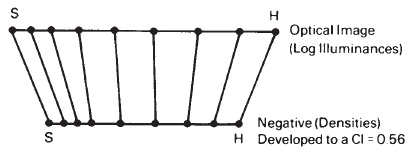
Figure 6-11 The relationship between the optical image at the film plane and the densities in the negative.
are invariably processed to contrast indexes less than 1.0. Thus, significant compression of tones occurs at the negative-making stage, with the darker shadow tones suffering the greatest amount of compression.
At this stage of the process, the photographer has many image controls available. Among the more important are:
1.Film type. To a great extent, the properties of the emulsion determine the shape of the characteristic curve. For example, lithographic (or lith) emulsions generally will produce curves with slopes greater than 1.0 under most development conditions, while pictorial films will produce slopes less than 1.0 under most development conditions. Therefore, if the input log exposure range is very short, the photographer would do well to select a lith-type emulsion. If, however, the log exposure range is long (1.3 or greater), a pictorial film would be a better choice. Specialized emulsions have been designed to handle log exposure ranges of excessive lengths (1,000,000:1 and greater).
2.Development. As discussed in Chapter 5, the length of development time provides a useful control for obtaining a variety of curve shapes (slopes) in the film. For pictorial applications, the concept of contrast index provides the most useful guide for estimating the required slope. The recommended development times found in most manufacturers’ literature are those which will produce a contrast index of approximately 0.56, since this is the slope that will convert an average outdoor scene into a normal-con-trast negative for diffusion enlargers. Flatter scenes will provide a shorter input range to the film and require a steeper slope to maintain a constant density range (contrast) in the negative. Contrasty subjects will provide the film with a longer range of log exposures and consequently require a lower slope to maintain the density range at the normal level. Thus, development provides the photographer with a powerful tool for contrast control in tone reproduction.
3.Exposure. The task here is to select the appropriate /-number and shutter speed to place the shadow-detail area of the subject at an exposure that will produce the minimum useful density for shadow detail in the negative. If less exposure is given, less shadow detail will result. If more exposure is given, greater shadow detail will result. Thus the /-number and shutter speed selected will have the greatest influence upon reproduction of the shadow tones. It is important to note that underexposure by more than one-half stop introduces a compression of shadow tones that cannot be adequately compensated for in later stages of the process. On the other hand, with typical pictorial subjects and films, overexposure by as much as four stops can be compensated for in the later stages but with the result of increased print exposure and grainier prints.
The Making of the Positive
The third major stage of this system is the making of the positive. For the example that follows, the reproduction will be in the form of a reflection print. When printing a negative, the negative’s densities control the exposures that the paper will receive. The thinner shadow areas of the negative will allow more light to strike the paper than will the denser highlight areas. Consequently, the output of the negative in the form of transmission densities can be related to the input of the photographic paper in the form of log exposures, which explains the positioning of quadrant III in Figure 6-12. Quadrant III represents the characteristic curve of a normal grade of black-and-white photographic paper.
The optimum contrast index for film development depends on scene contrast, type of enlarger, and paper contrast grade.
A print density of 0.04 above base density is considered appropriate for diffuse subject highlights, reserving paper white for images of light sources and specular reflections. The curve in quadrant IV of a tone reproduction diagram represents the relationship between the print tones and the subject tones.
The curve shape selected for this quadrant is based on the relationship between the density range of the negative and the useful log-exposure range of the paper. In Chapter 5, we saw that pictorial negatives generally are best printed on a paper in which the negative density range is equivalent to the paper’s useful log exposure range. In this example, the negative has a density range of 1.05 and therefore requires a paper curve having a useful log-exposure range of 1.05, as does the curve in quadrant III of Figure 6-12.
The f-number and printing time of the negative determine the location of the characteristic curve in quadrant III relative to the left and right position. The best reproduction is generally obtained when the useful shadow density of the negative produces a density in the print equal to 90% of the maximum density of which the print material is capable, which is the basis for the location of the paper curve in quadrant III.
If the relationship between the negative and the paper is correct, the diffuse highlights of the negative should generate a density in the print that is approximately 0.04 greater than the
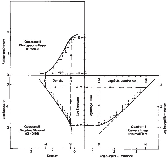
Figure 6-12 The combined effect of the transfer of camera flare through the negative characteristics and onto the print characteristics.
base density of the print. The broken shadow-detail line is extended upward from quadrant II, where it is reflected from the negative curve until it intersects with the print curve at its density of 90% of the maximum density.
Likewise, the dashed diffuse-highlight line is extended upward until it strikes the paper curve at the density equivalent to 0.04 above the base plus fog of the paper. Both lines

Figure 6-13 The relationship between the negative densities and print densities.
are then reflected to the right, which is the way in which all of the dots on the print density line were generated. Figure 6-13 illustrates the relationship of the nine input tones to the paper (from the negative densities) and the nine output tones from the paper in the form of reflection densities. The midtones of the negative are expanded in the print, while the highlights of the negative are compressed.
Generation of the Tone-Reproduction Curve
In the last phase of the system, the tones generated in the print are compared to the tones that existed in the original scene. As illustrated in Figure 6-14, this

Figure 6-14 Complete objective tone-reproduction diagram for a pictorial system.
is achieved by extending the print tone lines from the photographic paper quadrant to the right into the fourth quadrant titled “Reproduction," and noting where they intersect the corresponding lines projected upward from the appropriate subject log luminances.
For example, in Figure 6-14 the line representing the diffuse highlight on the photographic paper curve has been extended into the fourth quadrant until it intersects the line extended upward from the diffuse highlight of the subject. The intersection of these highlight lines in quadrant IV determines the highlight point on the objective tone-reproduction curve. Likewise, the line representing the detailed shadow tone in the print is extended into the fourth quadrant until it intersects the line extended upward from the same tone in the subject, generating the shadow detail point of the tone-reproduction curve.
This procedure is repeated for each of the intermediate points to obtain the complete objective tone-reproduction curve in Figure 6-14 in the fourth quadrant. The shape of this curve can provide insight into the nature of the tone reproduction occurring in the photograph.
Alert readers will have noticed that a flare curve has not been included for the printing stage of the tone-repro-duction process. All optical systems have flare, which, as we have seen with camera flare, can significantly affect image contrast. In this discussion of tone reproduction, it is assumed that contact prints are being made so that flare is not a factor at the printing stage. If prints are to be made with an enlarger, two additional factors must be considered: flare and the Callier effect. Enlarger flare reduces contrast and the Callier effect increases contrast, but because the net effect of these two factors is different for diffusion and condenser enlargers, different data must be used for the two types of enlargers. The easiest way to incorporate this information into the four-quadrant tone reproduction system is to make the D-log H paper curves by projection-printing a step tablet with the type of enlarger that is to be used for future printing, being careful to mask the negative carrier down to the edges of the step tablet.1
Color films scatter very little light and therefore have a Callier Q factor of approximately 1.0.
The four-quadrant tone-reproduction diagram reveals that for normal tone reproduction image contrast is reduced in quadrants I and II.
In this idealized case, since correct exposure and development of the negative were achieved and the negative was correctly printed, the resulting tone-reproduction curve closely resembles that of the desired tone-reproduction curve for black-and-white reflection prints, illustrated in Figure 6-1. The 45° dashed line representing facsimile reproduction has been included in quadrant IV for comparison purposes only. Examination of the curve in quadrant IV reveals that the shadow region of the curve has a slope less than 1.0 (45°), indicating that the subject tones in the print have been compressed relative to those in the scene. This is also the case with the highlight region of the curve. In the midtone region, the slope is slightly greater than 1.0 (45°), indicating a slight expansion of midtone contrast in the print compared to the original scene.
Thus, in preferred tone reproduction for black-and-white reflection prints, there is often compression of shadow and highlight detail with an accompanying slight increase in midtone contrast. This relationship between tones in the photographic print and the tones in the original scene can also be illustrated as shown in Figure 6-15. In this representation, the nine different subject tones are equally spaced, indicating equal tonal differences. However, in the bar representing the print tones, the highlight and shadow tones have been significantly compressed, while the midtones have been slightly expanded. Again, this is typical of the negative-positive process when a reflection print is the final product.
At this point, it is useful to review the properties of the four-quadrant tone-reproduction diagram illustrated in Figure 6-14. This system represents a graphical model of the actual photographic process with respect to the reproduction of tone. The major limitations and strengths of the photographic system can be determined by such a diagram. For example, quadrant I represents the camera image as primarily affected by optical flare. Optical flare is an inescapable part of any photographic system that incorporates the projected image. Thus, the photographer must live with the compression of tone (loss of detail and contrast) that results from this problem. Little control can be exerted on the process at this stage except to use a lens shade and keep the lens clean.
Quadrant II represents the results of exposing and processing the film, and thus the production of the negative. At this point, the photographer can exert the greatest amount of
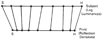
Figure 6-15 The relationship between the subject tones and the print tones.
control through the selection of the film type and the corresponding exposure and development conditions.
Quadrant III represents the making of the print and, consequently, is the last step in controlling print tones. The choice of paper grade is primarily dictated by the nature of the negative because development variation does not have any significant effect on paper contrast. The photographer has only limited control of the outcome at this stage of the process. Additionally, if a reflection print is being made, the photographer must accept the fact that the print’s tonal range will be less than that of the original subject.
The use of the four-quadrant tone-reproduction diagram also allows the photographer to see the expansion and compression of tones resulting at each stage of the process. For example, there is an inevitable loss of shadow contrast in the camera image caused by optical flare. Shadow contrast is further decreased when the shadow exposures are placed in the toe of the film’s characteristic curve, which is typically the case. A third reduction in shadow contrast occurs when the negative is printed and the shadow tones of the negative are placed on the shoulder of the paper’s characteristic curve. This explains the lowered contrast in the shadows of the final black-and-white reflection print.
The subject’s midtones are relatively unaffected by the camera’s flare characteristics and are typically exposed onto the straight-line section of the film’s characteristic curve. Although the midtone slope of the negative curve is usually less than 1.0 (0.5 to 0.6), the midtones of the negative are printed onto the mid-section of the paper’s characteristic curve where the slopes are considerably greater than 1.0 (1.5-3.0). The result is a mid-tone contrast in the print that
is only slightly greater than that of the original subject.
The highlights are also unaffected by optical flare at the camera stage and, when the film is exposed, are placed on the upper straight-line section of the characteristic curve. Thus, the only distortion introduced into the highlights when the negative is made is associated with the lowered slope in the negative’s characteristic curve. However, when the negative is printed, the highlight tones are placed in the toe section of the characteristic curve for the photographic paper and, as a result, suffer their greatest compression. This is the cause of the lowered slope and lessening of highlight detail in the tone-repro-duction curve in quadrant IV
It should be evident that all four quadrants can be described in terms of the slopes in the various areas (shadows, midtones, highlights) in each quadrant. Slope can be considered to be the rate of output for a given input, and the cumulative effect can be predicted by multiplying the slope of the curve in quadrant I by the slope of quadrant II, by the slope in quadrant III, to predict the slope that would result in quadrant IV If the concept of the average gradient (G) is substituted for slope, the relationship may be expressed by the following formula:
The average gradient in each quadrant represents the average slope between the diffuse highlight point and the shadow detail point. For example, in Figure 6-14 the average gradient for quadrant I is 0.82, for quadrant II it is 0.56, and for quadrant III it is approximately 1.78. Substituting these values in the above formula gives the following result:
0.82 × 0.56 × 1.78 = 0.82
The average gradient of tone-reproduction curve is the slope of a straight line connecting the highlight and shadow points on the curve.
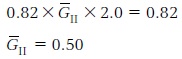
The calculations indicate that the average gradient for quadrant IV will be approximately 0.82, which is the case when the average gradient in quadrant IV is measured. A similar study may be done individually for the shadows, midtones, and highlights to assess the effect of each stage of the process on these areas. Often, this relationship between gradients can be used to work backwards in the system to predict the necessary gradient in any quadrant. For example, if it is desired to obtain an average gradient of 0.82 in quadrant IV (the reproduction quadrant), and it is known that a photographic paper with an average gradient of 2.0 will be used when making the print, and it is further known that the average gradient in the flare quadrant will be 0.82, the values can be substituted in the formula and the average gradient necessary in quadrant II can be predicted as follows:
In this fashion, the photographer can predict the necessary contrast index for the production of an excellent print under these conditions. By knowing the relationship between contrast index and development time, the photographer can actually determine the proper length of development time for any set of conditions. The concept of relating the various stages of the photographic process through the gradient at each stage often serves as the basis for some very useful nomographs that assist the photographer in predicting such things as the correct development time for the negative and the proper printing conditions of the resulting negative.
It should be evident that these nomographs represent abstractions or simplifications of the objective tone-reproduction diagrams discussed in this chapter and, as such, are more useful to the photographer. However, it is important to have an understanding of the input-output relationships at the various stages of the process and the rates affecting those stages—that understanding is most directly obtained through an understanding of the four-quadrant tone-reproduction diagram.
Tone Reproduction for a Digital System
There are obvious differences between tone reproduction between a film system and a digital system. When studying a digital system it is necessary to have an understanding of the scene brightness characteristics, the response of the imaging sensor, the performance of the display that the image is viewed on, and lastly the behavior of the paper. The four-quadrant tone reproduction plot can still be used to study a digital system, however the quadrants now take on a different look.
In a digital tone reproduction study, quadrant I illustrates the tonal transfer between the subject log luminances and the resulting digital counts, often referred to as the detector response (see Figure 6-16). An image sensor, either CCD or CMOS, will typically have a more linear relationship to the subject luminances than to the log luminance. Therefore, quadrant I provides the same input-output relationship that a film system has, however, the output values are now digital counts.
Quadrant II represents the ability to alter the image characteristics after the image is captured. In a film-based system this quadrant is the film quadrant. Altering the processing of the film would control the output. For a digital tone reproduction study this quadrant can be thought of as representing the processing or altering of the digital

Figure 6-16 Four quadrant plot for a digital tone reproduction study.
image or data. In a digital system, there are many alterations that can be applied to the digital data, such as adjusting the contrast or color balance of the image or sharpening an image. Although these operations are done with complex math, all the operations can be combined into one look-up table or LUT. A LUT provides a new output digital value for each input digital count. Therefore, quadrant II is represented as a LUT to apply tonal alterations. If no modifications to the image take place, this would be a straight line with the input digital count value equal to the output digital count value.
In most digital applications, an image is first viewed on a display device such as a CRT or LCD monitor prior to printing. In some applications, this is where the tone reproduction study might end as a final print may not be required. Quadrant III illustrates the characteristics of that display device. The input is digital count that resulted from the results of the LUT applied in quadrant II. The output is monitor density. Monitor density is defined in Equation 6-3.
 (Eq. 6-3)
Several factors can affect this quadrant and the measurement of the luminance on the display. The settings for brightness and contrast will affect these readings. The recommendation is that these values should be set so as to provide the best linear relationship achievable between the display digital count and the screen density.
Quadrant IV provides the relationship between the final print that would be made from the image on the screen and the original scene luminances. The final print densities would be obtained using a reflection densitometer.
Tone Reproduction and the Zone System
The concepts of tone reproduction and the accompanying tone-reproduction diagrams are intended to provide the photographer with a basis for understanding the nature of the photographic process. Experience has shown that photographers who have a firm understanding of the materials and how to control them are those most likely to consistently produce high-quality images. However, it is recognized that the tone-reproduction diagrams presented in this chapter do not provide a convenient way for photographers to exert control over the process at the time images are being made.
The origins of the Zone System can be traced to the work done by engineers with light meters at the Weston Electrical Instrument Corporation in 1939.
"Without visualization the Zone System is just a five-finger exercise."—Ansel Adams
"One can choose to place any one luminance value on or in any one zone, but what governs the choice in the first place?"—Minor White
Ansel Adams lists the Zone Ranges as: 0 to X = full black to pure white, I to IX = dynamic range, II to VIII = textural range.
During the past several decades, there have been countless procedures proposed for the control of image quality through the manipulation of the various stages of the photographic process. For example, the early Weston exposure meter dial had U and O positions marked to represent shadow and highlight positions for a normal scene. A third position labeled N represented the average midtone position, and therefore the normal exposure. The U position was located four stops below the normal arrow, the O position three stops above the normal arrow. The difference between the U and O locations corresponded to a seven-stop range or a luminance ratio of 128:1 (or 160:1 rounded to the nearest whole stop).
Perhaps the most comprehensive system—certainly the best known— is the Zone System, which was proposed by Ansel Adams and further refined by Minor White and others. In its most elementary state, the Zone System provides the photographer with a vocabulary for describing the various stages of the photographic process from the original scene through the completion of the final print. In its more advanced form the Zone System will lead the photographer to proper exposure, development, and printing conditions in order to reproduce the scene in a given fashion. Thus the basic premise of the Zone System is that the photographer must visualize the final print from the appearance of the original subject before taking the photograph. Through knowledge of the capabilities and limitations of the photographic system, the photographer can then manipulate its various components to achieve this visualized result.
In tone-reproduction studies of pictorial systems, the subject properties are expressed in terms of luminances (candelas per square foot) and log luminances. In the Zone System, the subject is described in terms of subject values, which relate to different subject luminances that are labeled by Roman numerals for easy identification. The values are related to each other by factors of two (one camera stop); Value II reflects twice as much light as Value I, Value III reflects twice as much light as Value II and four times as much light as Value I, and so on.
Table 6-2 contains the 10 subject values commonly used in the Zone System and their definitions. Using these
Table 6-2 The relationship between various parts of a scene and the corresponding subject value in the Zone System
| Subject Value | Description |
| 0 | Absolute darkest part of a scene. Example: when photographing the side of a cliff containing a cave. |
| I | A very dark portion of the scene where the surface of an object can be detected. Examples: dark cloth in shade; surface is visible with slight texture. |
| II | A dark area of the scene showing strong surface texture; perceptible detail. Examples: surface of building in heavy shade; shadow of tree cast on grass in sunlight. |
| III | Darkest part of scene where tonal separation can be seen; texture and shape of objects are evident. Example: tree trunk in shade where texture of bark and roundness of trunk with shading are evident. |
| IV | The darker midtones of a scene; objects in open shade. Example: landscape detail in open shade; dark foliage; Caucasian skin in shadow. |
| V | The middle gray tone of the scene; 18% reflectance. Examples: dark skin; gray stone (slate); clear north sky. |
| VI | The lighter midtones of a scene. Examples: average Caucasian skin in direct light; shadows on snow in sunlit scene. |
| VII | A very light area of the scene containing texture and detail. Examples: light skin in direct light; snow-covered objects with sidelighting. |
| VIII | The diffuse highlights (nonspecular) of the scene; white surfaces showing texture. Examples: white shirt in direct light; snow in open shade; highlights on Caucasian skin. |
| IX | The specular (glare) highlights of the scene; surface is visible but no texture. Examples: glare reflections from water, glass, and polished metal; fresh snow in direct sunlight. |
| X | The absolute brightest part of the scene. Example: a light source (sun, tungsten bulb, flash lamp, etc.) included in the field of view. |
definitions, the contrast of the original subject can be described in terms of the number of values it contains. For example, the scene-luminance measurements by Jones and Condit that led to the average luminance ratio of 160:1 were made on the darkest and lightest areas of the scene. These areas most nearly correspond to Values I and VIII in the Zone System. This means that the typical outdoor scene contains eight values: I, II, III, IV, V, VI, VII, and VIII. Furthermore, since each value is related to the next by a factor of two (one camera stop), such a scene contains a seven-value range (VIII -I = VII), and the ratio of the extreme values can be found by multiplying 2 times itself 7 times (27). The resulting ratio of 128:1 compares closely with the results of the Jones and Condit study.
Thus, in Zone System terminology, the typical outdoor scene contains eight values and is said to cover a seven-stop range. If a scene contains fewer than eight values, it is a flatter-than-normal scene, while a scene with more than eight values would be described as a contrasty scene. It is important to note that many references describe the average outdoor scene as containing five (or some other number) values ranging typically between Value III and Value VIII. The discrepancy is due to at least two factors. The first is associated with defining exactly what is meant by the terms detailed shadow and textured highlight. Obviously, the opinions of photographers will differ as a result of esthetic judgments. The second reason (and perhaps a more fundamental one) is related to the definition of a value. Some references define a value as an interval—a difference between two tones—while others state that it is a specific tone or subject luminance. This problem will cause a one-value discrepancy, since the number of intervals between tones will always be one less than the number of tones. In all discussions of the Zone System in this text, a value is defined as a specific tone and the difference between tones as a value range. The difference between tones is also expressed as a stop range, log luminance range, and luminance ratio.
F-numbers are positions on a scale while f-stops are the intervals between positions.
The Zone System Personal Speed Index is based on a negative density of 0.10 above base-plus-fog density for Zone I.
In the late 1800s, the photographer Dr. P H. Emerson put this question to Hurter and Driffield, the fathers of photographic sensitometry: "Suppose I want to photograph three houses, a white one, a gray one, and a black one. What is it you say I have to do to secure a truthful rendering of tone; what is it you say I can alter by development, and what is it I cannot alter?"
The value range of a subject can be converted to a log luminance range by simply multiplying the number of camera stops (factors of two) it contains by 0.30, the log value of one stop. Thus the average outdoor scene containing eight values covers a seven-stop range, which will give a log luminance range of 2.1 (7 X 0.3 = 2.1) and a luminance ratio of 128:1. A flat scene containing only five values covers a four-stop range and gives a log subject luminance range of 1.2 (4 X 0.3 = 1.2) or a ratio of 16:1. A contrasty scene containing nine values will cover an eight-stop range and give a log range of 2.4 (8 X 0.3 = 2.4) or a ratio of 256:1. Therefore, in its initial application the Zone System provides the photographer with a method of describing and quantifying the tonal values of the original scene. In the more technical tone-reproduction system, this correlates with the determination of the subject luminance ratio and ultimately the log subject luminance range as the principal description of the subject contrast.
In its second phase, the Zone System provides a way to determine the proper exposure and film development to obtain a normal-contrast negative. However, as with all systems of image control, it is necessary to test the film extensively to determine its characteristics. In the Zone System this invariably involves determining the camera exposure necessary to obtain the details desired in a particular shadow value, and the development necessary to correctly reproduce a given highlight value. Typically, the photographer would arrive at a personal working film speed and would determine the relationship between development time and contrast in the negative.
In this context, the subject values are translated into exposure zones, which are described by a similar set of Roman numerals. Although subject values can be measured in candelas per square foot (c/ft2), they are typically determined through visual (subjective) evaluation of the scene. Exposure zones (or, more simply, zones) are used to describe the input exposure scale of the film and are more technical. Thus a given subject value may be placed in any exposure zone, with the other values falling on the exposure scale where they may. Typically, an area of important shadow detail is placed in a lower exposure zone (Zone II or III), with the higher values (highlights) falling in higher zones, depending upon their lightness.
In Zone System terminology, the development time necessary to make a typical outdoor scene (eight values) results in a negative of normal contrast (density range equal to 1.10 for printing with a diffusion enlarger) is identified as "N” development. The development time necessary to make a nine-value subject result in a nor-mal-contrast negative (density range of 1.10) is defined as "N minus one zone,” or simply, "N minus 1.” Similarly, a subject containing only six values would require N plus 2 development to yield a normal-contrast negative.
The concept of zone development is related to the use of a normal contrast index for film development. "N minus” development is associated with lower-than-normal contrast-index values, while "N plus” development is associated with higher-than-normal contrast indexes. In the Zone System, "N plus” development is often referred to as expansion, while "N minus” development is referred to as compaction (see Table 6-3).
Table 6-3 Development index for Zone System
| Development Index for Zone System | Contrast Index | |
| Diffusion | Condenser | |
| N + 2 | 0.72 | 0.55 |
| N + 1 | 0.63 | 0.47 |
| N | 0.56 | 0.42 |
| N - 1 | 0.53 | 0.39 |
| N - 2 | 0.50 | 0.37 |
Therefore, the function of the Zone System at this stage is to assist the photographer in placing the important shadow value at some minimum useful position (Exposure Zone II or III) in the toe of the characteristic curve, and to provide the proper development that will result in a normal-contrast negative, regardless of the original scene contrast. This phase of the Zone System is often summarized by the following statement: “Expose the film for the shadows and develop the negative for the highlights." If the photographer has provided correct exposure and development, the density values produced in the negative will just fill the reproduction capacity (useful log exposure range) of a normal grade of photographic paper.
Table 6-4 The relationship between the various reflection densities of the photographic paper and print values
| Value | Description |
| 0 | Maximum density of paper; principally determined by surface characteristics of print; absolutely no tonal separation. |
| 1 | In theory, a just-noticeable difference from the maximum density. Sensitometric tests indicate that this value is located at 90% of the maximum density. At print densities higher than this, texture is suppressed. |
| II | Darkest area of the print where strong surface texture is still maintained. Approximately equal to a density that is 85% of the maximum density. |
| III | Darkest area of the print where detail can be seen; in the shoulder of the curve where there is sufficient slope for tonal separation. |
| IV | The darker midtones of the print. The upper midsection of the curve is used, giving obvious tonal separation. |
| V | The middle gray tone of the print; 18% reflectance; reflection density of 0.70. Occurs in the middle of the curve, producing maximum tonal separation. |
| VI | The lighter midtones of the print. The lower midsection of the curve is used where the slope is still quite high, yielding good tonal separation. |
| VII | A very light area of the print containing texture and detail. The toe section of the curve is employed where the slopes and densities are low, causing tonal compression. |
| VIII | The diffuse (nonspecular) highlights of the print. The just-noticeable density difference above the paper’s base-plus-fog density. A reflection density of approximately 0.04 above base plus fog. |
| IX | The specular highlights of the print. This is the base-plus-fog density of the paper and is the absolute whitest tone obtainable in the print. |
| X | Base plus fog density of the paper; maximum white (same tone as print zone IX). |
The third phase of the Zone System involves the printing of the negative and, therefore, the production of print values. At this stage, the concept of zones can, again, be used to describe the appearance of the tones of gray in the print; however, the term print value is used instead of zone to differentiate it from the exposure scale of the negative. Since reflection prints are limited in the range of tones that can be produced, and since there is distortion present in the photographic process, the values of the print have different definitions. These are listed in Table 6-4. The goal is to produce a print in which the values of the original subject are reproduced as the desired values in the finished print. This phase of the Zone System is analogous to the third quadrant of the tone-repro-duction diagram, in which the characteristic curve of the photographic paper is inserted and the output expressed in terms of reflection densities.
At this point, the Zone System comes full cycle; the photographer views the final print and determines the closeness with which it matches the visualized print. The results of this evaluation provide the basis for future refinements and improvements of the system. At this stage, photographers rely upon their subjective opinion regarding the quality of the final image. However, the Zone System provides photographers with a vocabulary and a set of measurement concepts that can provide a clear understanding of the factors influencing the final result. In the objective tone-reproduction system, this relates closely to the fourth quadrant, which contains the tone-reproduction curve resulting from the combination of materials and processes used to make the photograph. In the tone-reproduc-tion system the quality of the final print can be assessed in terms of how closely it matches the aim curve for that particular system. In the Zone System, the quality of the reproduction is assessed relative to what the photographer visualized in the subject.
“The Zone System is … a codification of the principles of sensitometry worked out by Fred Archer and myself around 1939-40.” —Ansel Adams
“What one selects as the important shadow is a matter of personal choice and a choice that must be made afresh for each photograph.” —Minor White
“Caucasian skin in sunlight is rendered with an amazing illusion of reality as a Pr int Value VI.” —Minor White
The similarities between the tone-reproduction system and the Zone System are not the result of chance. The Zone System actually represents a practical simplification of the concepts of tone reproduction. It is not surprising then, that many photographers have trouble understanding and implementing the Zone System without understanding the tone-reproduction system. The relationship between the two systems can be illustrated in a variety of ways. First, consider Figure 6-17, which represents an adaptation of Zone System terminology to the conventional four-quadrant tone-repro-duction diagram. This figure reveals the distortions encountered by the original subject zones in their travels through the photographic process. Notice, for example, that the shadow values are compressed first because of the camera’s flare characteristics, second because they are placed in the toe section of the film curve, and third because they are placed in the shoulder section of the paper curve.
As a result, the print’s shadow values are considerably compressed compared to the shadow values in the subject. Although the highlight values in the subject are unaffected by camera flare, they are somewhat compressed by the minimum slope in the upper portion of the film curve, and greatly compressed as a result of being exposed onto the toe section of the paper curve. Thus the print’s highlight values are greatly compressed compared to the highlight values of the original subject.
The midtone subject values are relatively unaffected by camera flare but they are somewhat reduced in contrast because of the medium slope (less than 1.0) in the mid-section of the film curve, and they are greatly expanded in contrast because they are placed in the steep mid-section of the paper curve. As a result of these conditions, the midtone values in the print are slightly expanded compared to the midtone values in the subject. Thus there is not a simple one-to-one relationship between the values of the subject and the values in the final print.
The effects of various stages of the photographic process on the subject values can also be illustrated through the use of a bar diagram as shown in Figure 6-18. The horizontal bar designated Subject Values has been divided into 10 equal values, with the appropriate Roman numerals. Value I and Value VIII have been marked to indicate
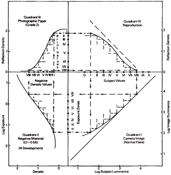
Figure 6-17 Objective tone-reproduction diagram illustrating the Zone System concept.
that they cover the range nearly equivalent to that of a typical outdoor subject. The Exposure Zones bar illustrates the effect of camera flare on the optical image at the back of the camera. Here only the lower (shadow) zones are being compressed.
A third bar represents the density values in the negative after it has been given “N" development (contrast index equal to 0.56). Notice that the shadow zones have been further compressed and now the midtone and highlight zones are compressed. The fourth bar illustrates the relationship of the print values for a glossy paper, assuming the negative was printed in a diffusion enlarger. The highlight values are considerably compressed compared to the corresponding zones in the original subject. The midtone values show a slight expansion, indicating they have a slightly higher contrast than the corresponding subject zones. Figures 6-17 and 6-18 are presented with the belief that an understanding of tone-reproduction principles will facilitate an understanding of the Zone System. In no way can such diagrams be substituted for the actual testing of the photographic system and for the creative use of the results. The four-quadrant tone-reproduction system, however, can be correlated with the Zone System provided the exposure meter and shutter are known to be accurate (or the errors are known and compensated for); and the flare, film, and paper curves are appropriate for the materials and equipment.
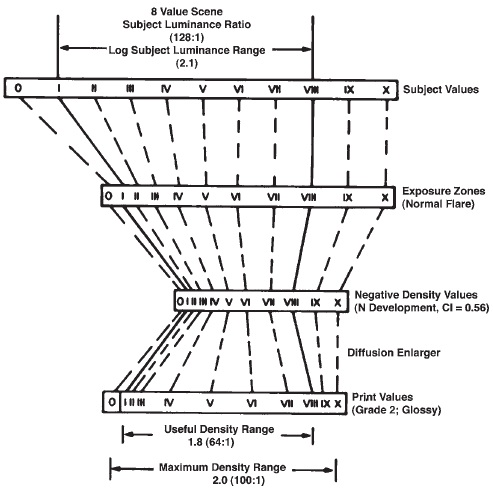
Figure 6-18 Distortion of zones that occurs at the major stages of the photographic process. (Adapted from Eastman Kodak Publication F-5.)
REVIEW QUESTIONS
- One of two identical photographic prints is viewed in front of a white background and the other is viewed in front of a black background, with identical illumination on the two prints. The print in front of the white background will tend to be judged as being . . .
- lighter
- darker
- The density of the center portion of the "preferred” tone-reproduction curve is . . .
- the same as the density of the corresponding subject area
- less than the density of the corresponding subject area
- more than the density of the corresponding subject area
- If a scene luminance ratio is 150:1 and the image illuminance ratio at the film plane of a camera is 50:1, the flare factor is . . .
- 1
- 2
- 3
- 50
- 100
- For normal exposure of the film, the shadow should be located on the curve in quadrant II where the . . .
- log exposure is 0.04 above the base-plus-fog log exposure
- log exposure is 0.1 above the base-plus-fog log exposure
- density is 0.04 above the base-plus-fog density
- density is 0.1 above the base-plus-fog density
- density is 90% of Dmax
- When selecting a grade of paper in quadrant III, the selection should be made so that the . . .
- density range of the paper matches the density range of the negative
- log exposure range of the paper matches the log exposure range of the negative
- density range of the paper matches the log exposure range of the negative
- log exposure range of the paper matches the density range of the negative
- The curve in quadrant IV for a film system represents the . . .
- relationship between the print and the negative
- relationship between the print and the subject
- relationship between the negative and the subject
- In the Zone System, diffuse highlights are represented by a subject value of
- VI
- VII
- VIII
- IX
- X
- In the Zone System, "N minus 1” development is recommended for . . .
- a six-value subject
- a seven-value subject
- an eight-value subject
- a nine-value subject
- a ten-value subject
1 Leslie Stroebel, “Print Contrast as Affected by Flare and Scattered Light.” PSA Journal, 48:3 (March 1982), pp. 39–42.