
Chapter 4
Photographic Optics

Photograph by Professor Michael Peres, Biomedical Photographic Communications, Rochester Institute of Technology
Image Formation with a Pinhole
The pinhole, as an image-forming device, has played an important role in the evolution of the modern camera. The observation of images formed by a small opening in an otherwise darkened room goes back at least to Aristotle's time, about 350 B.C.—and, indeed, the pinhole camera still fascinates many of today's photography students because of the simplicity with which it forms an image. The darkened room, or camera obscura, evolved into a portable room that could be moved about and yet was large enough to accommodate a person. The portable room in turn shrank to a portable box with a small opening and tracing paper, used as a drawing aid. By about 1570, the pinhole was replaced by a simple lens that produced a brighter image that was easier to trace. The name camera obscura survived all these changes.
Going back to the discussion of light in Chapter 1 and the corpuscular theory of light, pinholes are able to form images because light travels in a straight line. For each point on an object, a reflected ray of light passing through the pinhole will fall on only one spot on the ground glass, film, or digital sensor. Because light rays from the top and bottom of the scene and from the two sides cross at the pinhole, the image is reversed vertically and horizontally so that lettering in a scene will appear correct on the ground glass if it is viewed upside down (see Figure 4-1) and on film images viewed through the base.
A pinhole camera has two components—the pinhole-to-film or image distance, and the diameter of the pinhole itself. If a pinhole is used on a view camera or other camera having a bellows, it is the equivalent of a zoom lens because the image size will increase in direct proportion to the pinhole-to-film distance. The angle of view, on the other hand, will decrease as the image distance increases (see Figure 4-2). Because a pinhole does not focus light as a lens does, changing the image distance has little effect on the sharpness of the image. However, when the image is examined critically, it is found that there is an optimum pinhole-to-film distance for a pinhole of a given diameter.
The pinhole camera is still celebrated yearly with Worldwide Pinhole Photography Day http://www. pinholeday.org/

Figure 4-1 Reversal of the image vertically and horizontally by the crossing of the light rays at the pinhole produces correct reading of the lettering if viewed upside down from the rear.
Image definition varies with the size of the pinhole aperture, and there is an optimum size for a given pinhole-to-film distance.
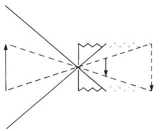
Figure 4-2 As the pinhole-to-film distance increases, the image size increases and the angle of view decreases.
Increasing the size of a pinhole from the optimum size allows more light to pass, which will increase the illuminance at the film plane and reduce the exposure time, but it also reduces the image sharpness. Decreasing the pinhole size, however, does not increase image sharpness. When the size is decreased below the optimum size for the specified pinhole-to-film distance, diffraction causes a decrease in sharpness (see Figure 4-3). The optimum pinhole size (Eq. 4-1) can be calculated with the formula

Figure 4-3 Three photographs made with pinholes of different sizes one-half the optimum size (A), the optimum size (B), and two times the optimum size (C). The images represent small sections cropped from 8 × 10-inch photographs.
 (Eq.4-1)
where D is the diameter of the pinhole in inches, and f is the pinhole-to-film distance in inches (see Table 4-1).* For example, with a pinhole-to-film distance of 8 inches, the diameter of the optimum size pinhole is about 1/50 inch. A No. 10 needle (a very fine sewing needle) will produce a pinhole of approximately this size.
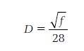
If millimeters are used as the unit of measurement, the following formula (Eq. 4-2) should be used:
 (Eq.4-2)
There is a basic pinhole formula that takes into account the wavelength of the light, D = ^2.5 λ f , where λ is the average wavelength of the exposing radiation in millimeters. For white-light and panchromatic film, a value of 500 nm (.00050 mm) is used. The optimum pinhole size is somewhat smaller for photographs made with ultraviolet radiation and somewhat larger for photographs made with infrared radiation. Doubling the wavelength or the pin-hole-to-film distance will increase the size of the optimum pinhole by a factor of the square root of 2 or 1.4. Various references do not agree on the constant in the formula, and the 2.5 constant used above represents an average value.
Pinholes can be made by pushing a needle through a piece of thin, opaque material, such as black paper, or drilling a hole in very thin metal. It is also possible to make a pinhole by crossing a vertical slit in one piece of thin material with a horizontal slit in another. The fact that this pinhole is square rather than round is of no great importance. Placing the vertical and horizontal slits at different distances from the film produces different scales of reproduction for the vertical and horizontal dimensions of objects being photographed, that is, an anamorphic image. Because the vertical slit controls the horizontal image formation, placing the vertical slit at double the distance of the horizontal slit from the film will produce a horizontally elongated or stretched image with a 2:1 ratio of the two dimensions (see Figure 4-4).
Table 4-1 Optimum pinhole diameters for different pinhole-film distances
| f (Distance) | D (Diameter) | F-N (F-Number) 1 |
| 1 in. | 1/140 in. | f/140 |
| 2 in. | 1/100 in. | f/200 |
| 4 in. | 1/70 in. | f/280 |
| 8 in. | 1/50 in. | f/400 |
| 16 in. | 1/35 in. | f/560 |
D =f /141 (in.) Optimal pinhole size equation for focal length in inches
D = f/28 (mm.) Optimal pinhole size equation for focal length in millimeters
F - N = f/D
Anamorphic images can be produced with a pinhole formed by vertical and horizontal slits at different distances from the film.
Note that throughout the discussion of pinhole cameras, it was assumed that film was the light-sensitive material. Pinhole images can be created by replacing the lens on a digital camera with a pinhole.
Image Formation with a Lens
A positive lens produces an image by refracting light so that all the light rays falling on the front surface of the lens from an object point converge to a point behind the lens (see Figure 4-5). If the object point is at infinity or a large distance, the light rays will enter the lens traveling parallel to each other, and the image point where they come to a focus is referred to as the principal focal point. The focal length can then be determined by measuring the distance from the principal focal point to the back nodal point—roughly the middle of a single-element lens (see Figure 4-6). Reversing the direction of light through the lens with a distant object on the right produces a second principal focal point and a second focal length to the left of the lens, as well as a second nodal point (see Figure 4-7). The two sets of terms are distinguished by the adjectives object (or front) and image (or back)—for example, front principal focal point and back principal focal point.
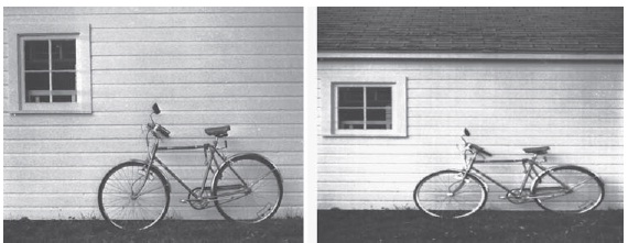
Figure 4-4 An anamorphic pinhole photograph (right) made with a vertical slit placed 1.5 times as far from the film as a horizontal slit. The comparison photograph was made with a camera lens.
Positive lenses are thicker in the center than at the edges. Negative lenses will not form real images that can be recorded on film.

Figure 4-5 Image formation with a positive lens.

Figure 4-6 The back focal length is the distance between the back nodal point and the image of an infinitely distant object.

Figure 4-7 The front focal length is found by reversing the direction of light through the lens.
All positive lenses are thicker at the center than at the edges and must have one convex surface, but the other surface can be convex, flat, or concave (see Figure 4-8). The curved surfaces are usually spherical, like the outside (convex) or inside (concave) surface of a hollow ball. Actually, this is not the best shape for forming a sharp image, but it has been widely used because lenses having flat and spherical surfaces are easier to mass produce than those having other curved surfaces, such as parabolic. If the curvature of a spherical lens surface is extended to produce a complete sphere, the center of that sphere is then identified as the center of curvature of the lens surface. A straight line drawn through the two centers of curvature of the two lens surfaces is identified as the lens axis (see Figure 4-9). If one of the surfaces is flat, the lens axis is a straight line through the one center of curvature and perpendicular to the flat surface.
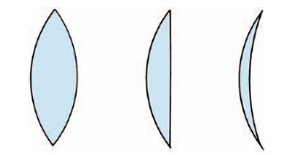
Figure 4-8 Three types of positive lenses: biconvex (left), plano-convex (center), and positive meniscus (right).

Figure 4-9 The lens axis is a straight line through the centers of curvature of the lens surfaces.
The optical center of a lens is a point on the lens axis where an off-axis undeviated ray of light crosses the lens axis. All rays of light that pass through the optical center are undeviated—that is, they leave the lens traveling parallel to the direction of entry (see Figure 4-10). Object distance and image distance can be measured to the optical center when great precision is not needed— but when precision is required the object distance is measured from the object to the front (or object) nodal point, and the image distance is measured to the back (or image) nodal point.

Figure 4-10 All rays of light passing through the optical center leave the lens traveling parallel to the direction of entry.
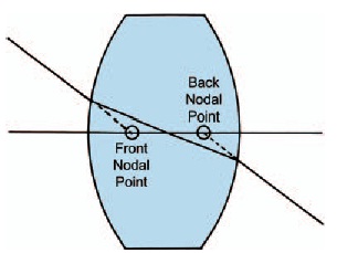
Figure 4-11 The nodal points can be located by extending the entering and departing parts of an undeviated ray of light in straight lines until they intersect the lens axis.
The front nodal point can be located on a drawing by extending an entering undeviated ray of light in a straight line until it intersects the lens axis, and the back nodal point by extending the departing ray of light backward in a straight line until it intersects the lens axis, as shown in Figure 4-11. A convention (which is not always observed) is to place objects to the left of lenses in drawings and images to the right, so that the light travels in the same direction that our eyes move when reading.
Manufacturers do not mark nodal points on lenses, but they can be located with a simple experiment.
Nodal points can also be located experimentally with lenses. The lens is first placed in a nodal slide, which is a device that enables a lens to be pivoted at various positions along its axis.
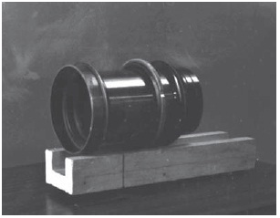
Figure 4-12 A simple nodal slide. The line on the side identifies the location of the pivot point on the bottom.

Figure 4-13 A professional optical bench, which permits the aerial image formed by a lens to be examined with a microscope.
For crude measurements, a simple trough with a pivot on the bottom is adequate (see Figure 4-12). Professional optical benches are used when greater precision is required (see Figure 4-13). The lens is first focused on a distant light source or the equivalent using a collimator with a light source placed at an appropriate closer distance, with the front of the lens facing the light source. The lens is then pivoted from side to side while the image is observed. If the image does not move as the lens is pivoted, the lens is being pivoted about its back (image) nodal point. If the image does move, however, the lens is moved either toward or away from the light source, the image is brought into focus by moving the focusing screen or the microscope, and the lens is again pivoted. This procedure is repeated until the image remains stationary when the lens is pivoted. The front (object) nodal point is determined the same way with the lens reversed so that the front of the lens is facing the image rather than the light source. Knowledge of the location of the nodal points can be useful, and it is unfortunate that the manufacturers of photographic lenses do not provide the locations of the two nodal points on their lenses.
Four practical applications for knowledge of the location of the nodal points are:
1. When accuracy is required, the object distance must be measured from the object to the front nodal point, and the image distance from the image to the back nodal point. Accurate determination of the focal length requires measuring the distance from the sharp image of a distant object to the back nodal point. Measurements to the nodal points are also made when using lens formulas to determine image size and scale of reproduction (see Figure 4-14). With conventional lenses that are relatively thin, little error will be introduced by measuring to the physical center of the lens rather than to the appropriate nodal point. With thick lenses and some lenses of special design—such as telephoto, retrofocus, and zoom lenses— considerable error can be introduced by measuring to the center of the lens. With these types of lenses, the nodal points can be some distance from the physical center of the lens, and may even be in front of or behind the lens. When distances are measured for objects or images that are not on the lens axis, the correct procedure is to measure the distance parallel to the lens axis to the appropriate nodal plane rather than to the nodal point. The nodal plane is a plane that is perpendicular to the lens axis and that includes the nodal point (see Figure 4-15).

Figure 4-14 For an object point on the lens axis, object distance is measured to the front nodal point, and image distance is measured from the image to the back nodal point.
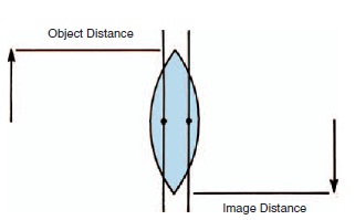
Figure 4-15 For an object point off the lens axis, object and image distances are measured in a direction that is parallel to the lens axis, to the corresponding nodal planes.
2. If a view-camera lens can be mounted on the camera so that it tilts and swings about the rear nodal point, the image will remain in the same position on the ground glass as these adjustments are made to control the plane of sharp focus. Otherwise the image will move up or down as the lens is tilted and sideways as it is swung, requiring realignment of the camera to restore the original composition. Unfortunately, little consideration is given to this factor in the design of most view cameras and the fact that the nodal points are at different positions with various types of lenses complicates the task.

Figure 4-16 Ideally, view cameras would permit the lens pivot point to be adjusted so that all lenses could be rotated about the back nodal point.
Although a sliding adjustment, as on a nodal slide, is the ideal solution, some improvement may be obtained with certain lenses by using a recessed lens board, a lens cone, or by reversing the lens standard (on modular view cameras having that feature) to change the position of the lens in relation to the pivot point on the camera (see Figure 4-16).
3. Panoramic image can be created by capturing multiple digital images and using stitching software to merge the images. If the camera is rotated on the back nodal point, the process of merging the images will be greatly simplified.
4. The task of making graphical drawings to illustrate image formation with lenses is greatly simplified by the use of nodal points and planes rather than lens elements. Whereas lens designers must consider the effect that each surface of each element in a lens has on a large number of light rays, many problems involving image and object sizes and distances can be illustrated and solved by using the nodal planes to represent the lens in the drawing, regardless of the number of lens elements. This procedure will be used in the following section.

Figure 4-17 Graphical drawings to show image formation using the lens elements (top) and the simpler thin-lens procedure (bottom).
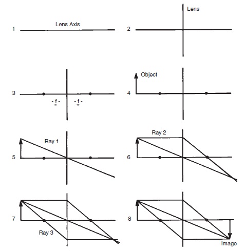
Figure 4-18 Making an actual-size or scale graphical drawing in eight steps.
Graphical Drawings
Graphical drawings are useful in that they not only illustrate image formation with lenses in simplified form, but they can be used as an alternative to mathematical formulas to solve problems involving image formation. The two drawings in Figure 4-17 show a comparison between the use of lens elements and the use of nodal planes. In the so-called thin-lens treatment, the two nodal planes are considered to be close enough to each other so that they can be combined into a single plane without significant loss of accuracy. If the drawing is to be used to solve a problem, rather than as a schematic illustration of image formation, the drawing must be made either actual size or to a known scale. The original drawing in Figure 4-18 was actual size, but the reproduction is smaller. The steps involved in making a graphical drawing are:
- Draw a straight horizontal line to represent the lens axis.
- Draw a straight vertical line to represent the lens.
- Place marks on the lens axis one focal length to the left and one focal length to the right of the lens. In this example, the focal length was 1 inch.
- Draw the object at the correct distance from the lens. In this example, the object was 2 inches tall and was located 2 inches from the lens.
- Draw the first ray of light from the top of the object straight through the optical center of the lens—that is, the intersection of the lens axis and the nodal plane.
- Draw the second ray, on a parallel to the lens axis, to the nodal plane, then through the back principal focal point.
- Draw the third ray through the front principal focal point to the nodal plane, then parallel to the lens axis.
- The intersection of the three rays represents the image of the top of the object. Draw a vertical line from that intersection to the lens axis to represent the entire (inverted) image of the object.
With a ruler, we can determine the correct size and position of the image from the original drawing. The image size was 2 inches and the image distance was 2 inches. From this we can generalize that placing an object two focal lengths in front of any lens produces a same-size image two focal lengths behind the lens.
This same drawing could be used as a one-quarter-scale drawing of a 4-inch focal length lens with an 8-inch-tall object located at an object distance of 8 inches. To determine the image size and image distance, the corresponding dimensions on the drawing are multiplied by 4 to compensate for the drawing's scale. Thus the image size is 2 inches × 4 = 8 inches, and the image distance is 2 inches × 4 = 8 inches.
Changing the distance between the object and the lens produces a change in the position where the image is formed. The relationship is an inverse one, so that as the object distance decreases, the image distance increases. Since the two distances are interdependent and interchangeable, they are commonly referred to as conjugate distances. Image size also changes as the object and image distances change.
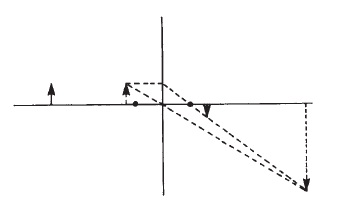
Figure 4-19 Moving an object closer to the lens results in an increase in both image distance and image size.
Moving an object closer to the lens results in an increase in both the image distance and the image size. These relationships are illustrated in Figure 4-19.
The closest an object can be placed to a lens and still obtain a real image is theoretically slightly more than one focal length. Placing an object at exactly one focal length from the lens causes the light rays from an object point to leave the lens traveling parallel to each other so that we can think of an image only as being formed at infinity. In practice, the closest an object can be placed to a camera lens and still obtain a sharp image is determined by the maximum distance the film or sensor can be placed from the lens. Problems of this type can be solved with graphical drawings. If the maximum image distance is 3 inches for a camera equipped with a 2-inch focal length lens, an actual-size or scale drawing is made starting with the image located 3 inches to the right of the lens. Three rays of light are then drawn back through the lens, using the same rules as before, to determine the location of the object.
Simple graphical drawings can be used to solve practical problems involving image size, scale of reproduction, and image and object distances.
With lenses that are too thick to be considered as thin lenses, or where greater accuracy is required, only small modifications of the thin-lens treatment are required. If it is known that the front and back nodal planes are separated by a distance of 1 inch in a certain lens, two vertical lines are drawn on the lens axis to represent the two nodal planes, separated by the appropriate actual or scale distance. The three rays of light are drawn from an object point to the front nodal plane, as before, but they are drawn parallel to the lens axis between the two nodal planes before they converge to form the image (see Figure 4-20).
The angle of coverage of a lens must be at least as large as the angle of view of the lens-camera combination.

Figure 4-20 The nodal planes are separated by an appropriate distance for thick-lens graphical drawings.
Angle of view can be determined with graphical drawings in addition to image and object distances and sizes. Angle of view is a measure of how much of the scene will be recorded on the light-sensitive material as determined by the lens focal length and the film or sensor size. Angle of view is usually determined for the diagonal of the film or sensor, which is the longest dimension, although two angles of view are sometimes specified, one for the film's or sensor's vertical dimension and one for the horizontal dimension. A horizontal line is drawn for the lens axis and a vertical line is drawn to represent the nodal planes, as with the thin-lens treatment above. A second vertical line is drawn one focal length (actual or scale distance) to the right of the nodal planes. The second vertical line represents the film or sensor diagonal, so it must be the correct actual or scale length.

Figure 4-21 The angle of view of a lens-film combination can be determined by drawing a line with the length equal to the film diagonal at a distance of one focal length from the lens. The angle formed by the extreme rays of light can be measured with a protractor.
The drawing in Figure 4-21 represents a 50-mm focal length lens on a 35-mm camera, where the diagonal of the image area is approximately 43 mm. Lines drawn from the rear nodal point (that is, the intersection of the nodal planes and the lens axis) to opposite corners of the film or sensor form an angle that can be measured with a protractor. No compensation is necessary for the drawing's scale, since there are 360° in a circle no matter how large the circle is drawn. The angle of view in this example is approximately 47°.
Two other focal length lenses, 15 mm and 135 mm, are represented in the drawing in Figure 4-22. The measured angles of view are approximately 110° and 18°. It is apparent from these drawings that using a shorter focal length lens on a camera will increase the angle of view, whereas using smaller film, as in using a reducing back on a large-format camera, will decrease the angle of view. Angle of view is determined with the film or sensor placed one focal length behind the lens, which corresponds to focusing on infinity. When a camera is focused on nearer objects, the lens-to-film or sensor distance increases, and the effective angle of view decreases.
Graphical drawings are especially helpful for beginning photographers because they make it easy to visualize the relationships involved. With experience, it becomes more efficient to solve problems relating to distances and sizes using mathematical formulas. Most problems of this nature that are encountered by practicing photographers can be solved by using these four simple formulas:
- 1/f = 1/u + 1/v
- R = v/u
- R = (v - f)/f
- R = f/(u-f
where
f= focal length u = object distance v = image distance
R = scale of reproduction, which is image size/object size, or I/O.
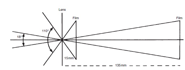
Figure 4-22 Angles of view for 15-mm and 135-mm focal length lenses with 35-mm film
The focal length of an unmarked lens can be determined with formula 1 by forming a sharp image of an object, measuring the object and image distances, and solving the formula for f Thus, if the object and image distances are both 8 inches, the focal length is 4 inches. The formula illustrates the inverse relationship between the conjugate distances u and v, whereby moving a camera closer to an object requires increasing the lens-to-film or lens-to-sensor distance to keep the image in sharp focus.
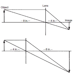
Figure 4-23 Since the object and image distances are interchangeable, sharp image can be found with a lens in two different positions between object and film or sensor.
It also illustrates that u and v are interchangeable, which means that sharp images can be formed with a lens in two different positions between an object and the film or sensor. For example, if a sharp image is formed when a lens is 8 inches from the object and 4 inches from the film or sensor, another (and larger) sharp image will be formed when the lens is placed 4 inches from the object and 8 inches from the film or sensor (see Figure 4-23). Exceptions to the statement that sharp images can be formed with a lens in two different positions are (a) when the object and image distances are the same, which produces an image that is the same size as the object, and (b) when an image distance is larger than the maximum bellows extension on the camera, so that the lens cannot be moved far enough away from the image plane to form the second sharp image.
The scale of reproduction for a photograph is equal to the image size divided by the object size or the image distance divided by the object distance.
A problem commonly encountered by photographers is determining how large a scale of reproduction (R) can be obtained with a certain camera-lens combination. If a view camera has a maximum bellows extension (v) of 16 inches and is equipped with an 8-inch focal length (f) lens, formula 3 would be selected: R = (v — f)/f = (16 − 8)/8 = 1, where the image is the same size as the object. Although to obtain a larger image, a longer focal length lens can be used when the camera cannot be moved closer (see formula 4), a shorter focal-length lens would be used to obtain a larger image in close-up work when the maximum bellows extension is the limiting factor. Replacing the 8-inch lens above with a 2-inch lens would increase the scale of reproduction from R = 1 to R = 7. [(16 − 2)/2 = 7].
Depth of field is the range of distances within which objects are imaged with acceptable sharpness.
Depth of Field
Camera lenses can be focused on only one object distance at a time. Theoretically, objects in front of and behind the object distance that is focused on will not be imaged sharply on the film. In practice, acceptably sharp focus is seldom limited to a single plane. Instead, objects somewhat closer and farther away appear sharp. Depth of field is defined as the range of object distances within which objects are imaged with acceptable sharpness. Depth of field is not limited to the plane focused on because the human eye has limited resolving power, so that a circle up to a certain size appears as a point (see Figure 4-24). The largest circle that appears as a point is referred to as the permissible circle of confusion.
Permissible Circle of Confusion
The size of the largest circle that appears as a point (circle of confusion) depends upon viewing distance. For this reason, permissible circles of confusion are generally specified for a viewing distance of 10 inches, and 1/100 inch is commonly cited as an appropriate value for the diameter. Even at a fixed distance, the size of the permissible circle of confusion will vary with such factors as differences in individual eyesight, the tonal contrast between the circle and the background, the level of illumination, and the viewer's criteria for sharpness. Nevertheless, when a lens manufacturer prepares a depth-of-field table or scale for a lens, these variables must be ignored. A single value is selected for the permissible circle of confusion that seems appropriate for the typical user of the lens. Although many photographic books that include the subject of depth of field accept 1/100 inch as being appropriate, there is less agreement among lens manufacturers. A study involving a small sample of cameras designed for advanced amateurs and professional photographers revealed that values ranging from 1/70 to 1/200 inch were used—approximately a 3:1 ratio. Two different methods will be considered for evaluating depth-of-field scales and tables for specific lenses.

Figure 4-24 Depth of field is the range of distances within which objects are imaged with acceptable sharpness. At the limits, object points are imaged as permissible circles of confusion
One procedure is to photograph a flat surface that has good detail at an angle of approximately 45°, placing markers at the point focused on and at the near and far limits of the depth of field as indicated by the depth-of-field scale or table, as shown in Figure 4-25. The first photograph should be made at an intermediate f-number, with additional exposures bracketing the f-number one and two stops on both sides, with appropriate adjustments in the exposure time. A variation of this procedure is to use three movable objects in place of the flat surface, focusing on one and placing the other two at the near and far limits of the depth of field as indicated by the scale or table.
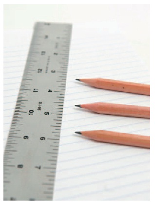
Figure 4-25 Depth-of-field scales and tables can be checked by photographing an object at an angle with markers placed at the point focused on and at the indicated near and far limits of the depth of field. A 6 × 8-inch or larger print should be made so that it can be viewed from the “correct” viewing distance. (Photograph by Oscar Durand, Photojournalism student, Rochester Institute of Technology.)
To judge the results, 6 × 8-inch or larger prints should be made without cropping and viewed from a distance equal to the diagonal of the prints. The diagonal of a 6 × 8-inch print is 10 inches, which is considered to be the closest distance at which most people can comfortably view photographs or read. If the photograph made at the f-number specified by the depth-of-field scale or table has either too little or too much depth of field when viewed at the correct distance, the photograph that best meets the viewer's expectation should be identified from the bracketing series. A corresponding adjustment can be made when using the depth-of-field scale or table in the future.
When a camera is focused on the hyperfocal distance, everything should appear sharp in the photograph from infinity to one-half the hyperfocal distance.

Figure 4-26 The hyperfocal distance is the closest distance that appears sharp when a lens is focused on infinity (top), or the closest distance that can be focused on and have an object at infinity appear sharp (bottom).
The second procedure involves determining the diameter of the permissible circle of confusion used by the lens manufacturer in calculating the depth-of-field scale or table. It is not necessary to expose any film with this procedure. Instead, substitute values for the terms on the right side of the formula C = f2/(N × H) and solve for C, where C is the diameter of the permissible circle of confusion on the film, f is the focal length of the lens, N is any selected f-number, and H is the hyperfocal distance at that f-number.
Hyperfocal distance can be defined in either of two ways: (a) the closest distance that appears sharp when a lens is focused on infinity, or (b) the closest distance that can be focused on while having an object at infinity appear sharp. Although the two procedures are different, the results will be essentially the same. When a lens is focused on the hyperfocal distance, the depth of field extends from infinity to one-half the hyperfocal distance (see Figure 4-26). If f/22 is selected as the f-number with a 2-inch (50-mm) focal length lens, the hyperfocal distance can be determined either from a depth-of-field table or from a depth-of-field scale on the lens or camera by noting the near distance sharp at f/22 when the lens is focused on infinity. (If the near-limit marker on a DOF scale falls between two widely separated numbers, making accurate estimation difficult, set infinity opposite the far-limit marker, as shown in Figure 4-27, and multiply the distance opposite the near-limit marker by two.)

Figure 4-27 The hyperfocal distance can be determined from a depth-of-field scale either by focusing on infinity and noting the near distance sharp at the specified f-number (top) or by setting infinity opposite the far-distance sharp marker and multiplying the near distance sharp by two (bottom). (Photograph by James Craven, Imaging and Photographic Technology student, Rochester Institute of Technology.)
Since the circle of confusion is commonly expressed as a fraction of an inch, the hyperfocal distance and the focal length must be in inches. The hyperfocal distance at f/22 for the lens illustrated is 21 feet or 252 inches. Substituting these values in the formula C = f2/(N × H) produces 22/22 × 252 or 1/1,386 inch. This is the size of the permissible circle of confusion on the negative, but a 35-mm negative must be magnified six times to make a 6 × 8-inch print to be viewed at 10 inches. Thus, 6 × 1/1,386 = 1/231 inch, or approximately half as large a permissible circle of confusion as the 1/100-inch value commonly used.
Note that the size of the permissible circle of confusion used by a lens manufacturer in computing a depth-of-field table or scale tells us nothing about the quality of the lens itself. The manufacturer can arbitrarily select any value, and in practice a size is selected that is deemed appropriate for the typical user of the lens. If a second depth-of-field scale is made for the lens in the preceding example based on the new calculated circle with a diameter of 1/200 inch, the new scale would indicate that it is necessary to stop down only to f/11 in a situation where the original scale specified f/22. Lens definition, however, is determined by the quality of the image for the object focused on, not the near and far limits of the indicated depth of field.
Depth-of-Field Controls
Photographers have three controls over depth of field: f-number, object distance, and focal length. Since viewing distance also affects the apparent sharpness of objects in front of and behind the object focused on, it is generally assumed that photographs will be viewed at a distance about equal to the diagonal of the picture. At this distance, depth of field will not be affected by making different-size prints from the same negative. For example, the circles of confusion at the near and far limits of the depth of field will be twice as large on a 16 × 20-inch print as on an 8 × 10-inch print from the same negative, but the larger print would be viewed from double the distance, making the two prints appear to have the same depth of field. If the larger print were viewed from the same distance as the smaller print, it would appear to have less depth of field. Cropping when enlarging will decrease the depth of field because the print size and viewing distance will not increase in proportion to the magnification.
Photographers can change the depth of field in photographs by changing f-number, the object distance, or the focal length of the camera lens.
Depth of Field and F-Number
The relationship between f-number and depth of field is a simple one, doubling the f-number doubles the depth of field. In other words, depth of field is directly proportional to the f-number, or D1/D2 = N1/N2. Thus, if a lens has a range of f-numbers from f/2 to f/22, the ratio of the depth of field at these settings would be D1/D2 = (f/22)/(f/2) = 11/1. Changing the f-number is generally the most convenient method of controlling depth of field, but occasionally insufficient depth of field is obtained with a lens stopped down to the smallest diaphragm opening or too much depth of field is obtained with a lens wide open. In these circumstances other controls must be considered.
Depth of field is directly proportional to the f-number.
Depth of Field and Object Distance
Depth of field increases rapidly as the distance between the camera and the subject increases. For example, doubling the object distance makes the depth of field four times as large. The differences in depth of field with very small and very large object distances are dramatic. In photomacrography, where the camera is at a distance of two focal lengths or less from the subject, the depth of field at a large aperture sometimes appears to be confined to a single plane (see Figure 4-28).
At the other extreme, by focusing on the hyperfocal distance, depth of field extends from infinity to within a few feet of the camera with some lenses (see Figure 4-29). The mathematical relationship between depth of field and object distance (provided the object distance does not exceed the hyperfocal distance) is represented by the formula. For example, if two photographs are made with the camera 5 feet and 20 feet from the subject, the ratio of the depths of field will be

Figure 4-28 Since depth of field varies in proportion to the o bject distance squared, photographs made at a scale of reproduction of 1:1 and larger tend to have a shallow depth of field. (Photograph by Oscar Durand, Photojournalism student, Rochester Institute of Technology.)

If, however, object distance is increased to obtain a larger depth of field when a camera lens cannot be stopped down far enough, it is necessary to take into account the enlarging and cropping required to obtain the same image size as with the camera in the original position. There is still a net gain in depth of field in moving the camera farther from the subject, even though some of the increase is lost when the image is cropped in printing. The net gain is represented by the formula D1/D2 = U1/ U2, which is the same as the preceding formula with the square sign removed.

Figure 4-29 Focusing on the hyperfocal distance produces a depth of field that extends from infinity to one-half the hyperfocal distance. (Photograph by Nanette L. Salvaggio.)
Depth of Field and Focal Length
There is an inverse relationship between focal length and depth of field, so as focal length increases, depth of field decreases. Before specifying the relationship more exactly, however, it is necessary to distinguish between situations where the different focal length lenses are used on different format cameras, such as 35-mm and 8 × 10-inch, and where the lenses are used on the same camera. When a large-format camera and a small-for-mat camera are each equipped with a normal focal-length lens, that is, a lens with a focal length about equal to the film diagonal, the depth of field will be inversely proportional to the focal length. For example, a 2-inch (50-mm) focal length lens on a 35-mm camera will produce about six times the depth of field of a 12-inch (305-mm) lens on an 8 × 10-inch camera. Even though enlarging negatives does not affect the depth of field, it is easier to compare the depth of field on two prints when they are the same size. Thus it would be appropriate to make an 8 × 10-inch enlargement from the 35-mm negative and a contact print from the 8 × 10-inch negative. The above relationship of depth of field and focal length is expressed as

Using the same two lenses on one camera produces a more dramatic difference in depth of field. It is now necessary to square the focal lengths so that D1/D2 = f22/f12 Comparing the depth of field produced with 50-mm and 300-mm focal-length lenses on a 35-mm camera, the ratio of the focal lengths is 1:6, and the ratio of the depths of field is 36:1. The great increase in depth of field with the shorter lens evaporates, however, if the camera is moved closer to the subject to obtain the same size image on the film as with the longer lens. In this example, the camera would be placed at distances having a ratio of 1:6 to obtain the same image size with the 50-mm and 300-mm lenses, and we recall that depth of field increases with the distance squared, so that the 36-times increase obtained with the shorter lens would be exactly offset by the reduction in object distance.
There is still a net gain in using a shorter focal-length lens on the same camera if the negative is enlarged and cropped to obtain the same image size and cropping on a print as that produced with a longer lens. This is essentially the same situation as using different format cameras each with a normal focal-length lens.
Depth of Focus
A 50-mm focal-length camera lens produces four times as much depth of field as a 100-mm focal-length lens, with all other conditions remaining the same.
Depth of focus can be defined as the focusing latitude when photographing a two-dimensional subject. In other words, it is the distance the film or sensor plane can be moved in both directions from the optimum focus before the circles of confusion for the image of an object point match the permissible circle of confusion used to calculate depth of field. It is important to note that for depth-of-field calculations it is assumed the image plane occupies a single flat plane, and for depth-of-focus calculations it is assumed that the subject occupies a single flat plane (see Figure 4-30). If a three-dimensional object completely fills the depth-of-field space, there is only one position for the film or sensor, and there is in effect no depth of focus and no tolerance for focusing errors.
Depth of focus refers to the focusing latitude when photographing a two-dimensional subject.
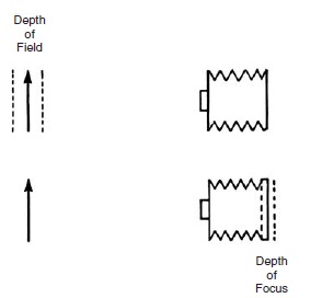
Figure 4-30 Depth-of-field calculations are based on the assumption that the twodimensional film is in the position of optimur focus (top). Depth-of-focus calculations are based on the assumption that the subject is limited to a two-dimensional plane (bottom).
The tilt and swing adjustments on view cameras provide control over image shape and the angle of the plane of sharp focus.
With a two-dimensional subject, the depth of focus can be found by multiplying the permissible circle of confusion by the f-number by 2. Thus, using 1/200-inch for the permissible circle of confusion on a 6 × 8 inch print or 1/1,200 inch on a 35-mm negative, the depth of focus is C × N × 2 = 1/1,200 × f/2 × 2 = 1/300 inch. It can be seen from this formula that depth of focus varies in direct proportion to the f-number, as does depth of field.
Whereas depth of field decreases as a camera is moved closer to the subject, depth of focus increases. This is because as the object distance decreases, the lens-to-film or sensor distance must be increased to keep the image in sharp focus, and this increases the effective f-number. It is the effective f-number, not the marked f-number, that is used in the formula.
Although increasing focal length decreases depth of field, it has no effect on depth of focus. The explanation is that at the same f-number the diameter of the effective aperture and the lens-to-film or sensor distance both change in proportion to changes in focal length so that the shape of the cone of light falling on the film or sensor remains unchanged. Because focal length does not appear in the formula C × N × 2, it has no effect on depth of focus.
Although changing film or sensor size would not seem to affect depth of focus, using a smaller film reduces the correct viewing distance and, therefore, the permissible circle of confusion. Substituting a smaller value for C in the formula C X N X 2 reduces the depth of focus.
View-Camera Movements
The basic view-camera movements include (1) an adjustment of the distance between the lens and the film to permit focusing on objects over a wide range of distances and to accommodate lenses having a wide range of focal lengths, (2) vertical and horizontal perpendicular movements of the lens and film to provide control over the positioning of the image on the film without altering image shape or the angle of the plane of sharp focus, and (3) tilt and swing movements of the lens and film to provide control over image shape and the angle of the plane of sharp focus. Some view cameras also have revolving backs that allow the film to be rotated in the film plane to provide angular control of cropping.
Perpendicular Movements
The circular area within which satisfactory image definition can be obtained is called the circle of good definition. The circle of good definition is one measure of the covering power of a lens (see Figures 4-31 and 4-32). If the circle of good definition is somewhat larger than the film, it will be possible to select different parts of the image within the circle to record on the film. View cameras typically have rising-falling adjustments to move the lens and/or film up and down, and lateral shifts to move the lens and/or film from side to side.

Figure 4-31 The diameter of the circle of good definition of a lens must be at least as large as the diagonal of the film.

Figure 4-32 Edges of the circle of good definition and the circle of illumination of a camera lens at the maximum aperture (left) and the minimum aperture (right). Stopping down increases the size of the circle of good definition and the abruptness of the transition from the illuminated area to the nonilluminated area.
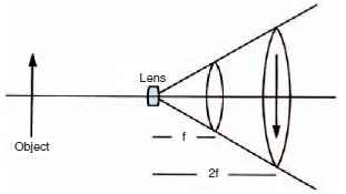
Figure 4-33 Changes in object and image distances do not affect the angle of coverage of a lens.
Angle of coverage is a second measure of the covering power of a lens, and can be determined by drawing straight lines from opposite sides of the circle of good definition to the back nodal point of the lens. Changes in object and image distances affect the size of the circle of good definition, but do not affect the angle of coverage (see Figure 4-33).
Back Movements and Image Shape
When the front of a long building or box-shaped object is photographed at an oblique angle, the near end is taller than the far end in the photograph, and the horizontal lines converge toward the far end. If the back of the camera is swung (that is, rotated about a vertical axis) parallel to the front of the object, the near and far ends will be the same size and the horizontal lines will be parallel in the photograph regardless of the camera-to-object distance (see Figure 4-34). Conversely, the ratio of image sizes and the convergence of the horizontal lines can be increased by swinging the back of the camera in the other direction, away from being parallel to the front of the object.
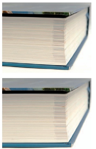
Figure 4-34 Photographing a book at an angle to show the front edge and one end causes the horizontal lines to converge with increasing distance (top). Swinging the back of the camera parallel to the front edge of the book eliminates the convergence of the horizontal lines in that plane (bottom). (Photographs by Oscar Durand, Photojournalism student, Rochester Institute of Technology.)
Tilting a camera upward to photograph a tall building causes the vertical subject lines to converge in the photograph for the same reasons as the horizontal lines, since the top of the building is at a greater distance from the camera than the bottom. To make the image lines parallel in this situation, the back is tilted (rotated about a horizontal axis) until it is parallel to the vertical subject lines, and the convergence can be exaggerated by tilting the back in the opposite direction. It would even be possible to make the top of the building appear to be larger than the bottom by overcorrecting, that is, by tilting the back to the vertical position and beyond.
Swinging and tilting the lens on a view camera will not alter the convergence of subject lines or the shape of the image.
Image shape is controlled by swinging and tilting the back of the camera. Image sharpness can be controlled by altering the angle of either the front or the back
Back Movements and Image Sharpness
In situations where the swing and tilt adjustments on the camera back are not needed to control the convergence of parallel subject lines or to otherwise control image shape, they can be used to control the angle of the plane of sharp focus in object space. Whereas only the back adjustments can be used to control image shape, either the back or lens adjustments can be used to control the angle of the plane of sharp focus. When both image shape and sharpness must be controlled, the back adjustments are used for shape (since there is no other choice) and the lens adjustments are used for sharpness.

Figure 4-35 When a camera is focused on an intermediate distance, the image of the far end comes to a focus in front of the film, and the image of the near end comes to a focus behind the film.
Figure 4-35 illustrates that the image of a distant object on the left comes to a focus closer behind the lens than the image of a nearby object on the right, as specified by the lens formula 1/ƒ = 1/u + 1/v, where the conjugate object and image distances vary inversely. To obtain a sharp image, the back is swung in a direction away from being parallel to the object plane containing the two object points—the opposite direction to that used to prevent convergence of parallel lines in the same object plane.
This relationship of the plane of the subject, the plane of the lens board, and the plane of sharp focus in image space is known as the Scheimpflug rule (see Figure 4-36).
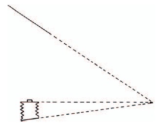
Figure 4-36 The convergence of the planes of the subject, the lens board, and the film illustrates the Scheimpflug rule for controlling the angle of the plane of sharp focus.
Lens Movements and Image Sharpness
The Scheimpflug rule indicates that if the back of the camera is left in the zero position with a subject that is at an oblique angle, the lensboard can be swung (or tilted) to obtain convergence of the three planes at a common location. The lensboard is swung toward a position parallel to the subject plane to obtain a sharp image, whereas the back of the camera was swung in the opposite direction.
Lens Types
Descriptive names applied to different types of camera lenses include normal, telephoto, catadioptric, wide-angle, reversed telephoto (retrofocus), supplementary, convertible, zoom, macro, macro-zoom, process, soft focus, and anamorphic. Considerable variations exist among so-called normal lenses, especially in the characteristics of focal length, speed, image quality, and price. The characteristic most common to normal-type lenses is an angular covering power of about 53°, which is just sufficient to cover the film when the focal length is equal to the film diagonal. The rule of thumb that recommends using a lens having a focal length about equal to the film diagonal is reasonable for normal-type lenses with most cameras, but longer focal-length normal-type lenses should be used with view cameras to provide sufficient covering power to accommodate the camera movements. In the past, many cameras were built with the lens permanently attached, the implication being that one lens should be able to satisfy all picture-taking needs. Most contemporary cameras are constructed so that other lenses can be substituted, enabling photographers to take advantage of the great variety of special-purpose lenses available.
Telephoto Lenses
Telescopes and microscopes were invented to enable us to see distant objects, as well as small objects more clearly. Photographers often want to record larger images of these distant and small objects than can be produced with lenses of normal focal length and design. We know that the image size of a distant object is directly proportional to the focal length. Thus, to obtain an image that is six times as large as that produced by a normal lens, the focal length must be increased by a factor of six, but the lens-to-film distance will also be increased six times unless the lens design is modified. The lens-to-film distance is shorter with telephoto lenses than with normal lenses of the same focal length. Compactness is the advantage of equipping a camera with a telephoto lens rather than a normal-type lens of the same focal length. Photographs made with the two lenses, however, would be the same with respect to image size, angle of view, linear perspective, and depth of field.
The basic design for a telephoto lens is a positive element in front of and separated from a negative element (see Figure 4-37). When a telephoto lens and a normal-type lens of the same focal length are focused on a distant object point, both images will come to a focus one focal length behind the respective back (image) nodal planes; but the lens-to-image distance will be smaller with the telephoto lens. The reason for the reduced lens-to-image distance is that the back nodal plane is located in front of the lens with telephoto lenses rather than near the center, as with normal lenses. It is easy to locate the position of the back nodal plane in a ray tracing of a telephoto lens focused on a distant object point, as in Figure 4-37, by reversing the converging rays of light in straight lines back through the lens until they meet the entering parallel rays of light. To determine the position of the back nodal point with an actual telephoto lens, the lens can be pivoted about various positions along the lens axis on a nodal slide until the image of a distant object remains stationary; or the lens and camera can be focused on infinity, whereby the back nodal point will be located exactly one focal length in front of the image plane. The position of the back nodal plane should be noted in relation to the front edge of the lens barrel, since this relationship will remain constant. If the back nodal plane is found to be located 2 inches forward of the front of a telephoto lens, two inches should be added to the distance from the front of the lens to the film any time the image distance (v) is used in a calculation, such as to determine scale of reproduction or the exposure correction for close-up photography. Although telephoto lenses are not generally used for close-up photography, the close-up range begins at an object distance of about ten times the focal length, which can be a considerable distance with a long focal length telephoto lens.
Telephoto lenses have shorter lens-to-film distances than normal-type lenses of the same focal length.
Catadioptric lenses contain mirrors and glass elements.

Figure 4-37 The lens-to-film distance is shorter for a telephoto lens (top) than for a normal-type lens (bottom) of the same focal length.

Figure 4-38 Catadioptric lenses make use of folded optics to obtain long focal lengths in relatively short lens barrels.
Catadioptric Lenses
Notwithstanding the shorter lens-to-film distance obtained with telephoto lenses compared to normal lenses of the same focal length, the distance becomes inconveniently large with very long focal-length telephoto lenses. Catadioptric lenses achieve a dramatic improvement in compactness through the use of folded optics. They combine glass elements and mirrors to form the image. The name catadioptric is derived from dioptrics (the optics of refracting elements) and catoptrics (the optics of reflecting surfaces). Figure 4-38 illustrates the principle of image formation with a catadioptric lens. A beam of light from a distant point passes through the glass element, except for the opaque circle in the center; it is reflected by the concave mirror and again by the smaller mirror on the back of the glass element, and it passes through the opening in the concave mirror to form the image on the film. The glass element and the opaque stop reduce aberrations inherent in the mirror system. Additional glass elements are commonly used between the small mirror and the film or sensor.
Location of the image nodal plane and the focal length of a catadioptric lens can be determined by the same methods described above for telephoto lenses. When the converging light rays that form the image on the film are reversed in straight lines on a ray tracing until they meet the entering rays of light, it can be seen that the image nodal plane is located a considerable distance in front of the lens, and the lens-to-image distance is small compared to the focal length (see Figure 4-39).
Catadioptric lenses are capable of producing images having excellent definition. There are also disadvantages with this type of lens. The long focal length means the lens diameter would have to be very large to match the low f-numbers commonplace on lenses of normal design. Since a variable diaphragm cannot be used with this type of lens, exposure must be controlled with the shutter or by using neutral-density filters, and there is no control over depth of field. An additional disadvantage is that f-numbers calculated by dividing the focal length by the effective aperture do not take into consideration the light that is blocked by the mirrored spot in the center of the glass element.
Wide-Angle Lenses
Two especially important reasons for substituting a shorter focal-length lens on a camera equipped with a lens of normal focal length and design are (a) the need to include a larger area of a scene in a photograph from a given camera position, and (b) the need to obtain a larger scale of reproduction when photographing small objects and the maximum lens-to-image distance capability of the camera is the limiting factor. In the latter situation, a shorter focal-length lens of normal design can be used satisfactorily because the diameter of the circle of good definition of the lens increases in proportion to the lens-to-image distance, which is necessarily larger for close-up photography and photomacrography. The same shorter focal-length lens would not have sufficient covering power to photograph more distant scenes where the lens-to-image distance is about equal to the focal length.
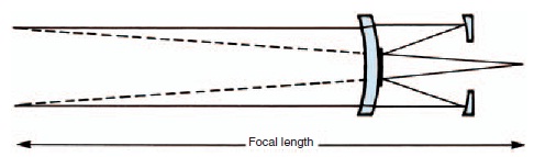
Figure 4-39 The image nodal plane and the focal length of a catadioptric lens can be determined by reversing the converging rays of light that form the image in straight lines until they meet the corresponding entering rays.
A wide-angle lens can be defined as a lens having an angular covering power significantly larger than the approximately 53° angle of coverage provided by a normal-type lens, or as having a circle of good definition with a diameter considerably larger than the focal length when focused on infinity (see Figure 4-40). Wide-angle lenses are not restricted to short focal-length lenses. It would be appropriate to use a wide-angle lens with a focal length equal to the film diagonal on a view camera where the extra covering power is needed to accommodate the view camera movements.
There is no distinctive basic design for wide-angle lenses comparable to the arrangement of positive and negative elements in telephoto lenses, except for that of the reversed telephoto wide-angle lenses. Early wide-angle lenses tended toward symmetry about the diaphragm, with few elements, and they usually had to be stopped down somewhat to obtain an image with satisfactory definition. Most, but not all, modern wide-angle lenses have a considerable number of elements, and they generally produce good definition even at the maximum aperture, with much less falloff of illumination toward the corners than the earlier lenses.
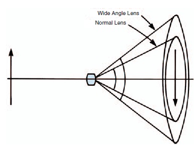
Figure 4-40 The covering power of a wide-angle lens compared to that of a normal-type lens of the same focal length. The images formed by the two lenses would be the same size.
The diameter of the circle of good definition of wide-angle lenses is considerably larger than the focal length.
Reversed telephoto wide-angle lenses are used on singlelens reflex cameras to avoid interference between the lens and the mirror.
Wide-angle lenses of the fisheye type are capable of covering angles up to 180°, but only by recording off-axis straight subject lines as curved lines in the image. At this time, rectilinear wide-angle lenses are available that cover an angle of 110° with a 15mm focal length on a 35-mm camera. There is no minimum angle of coverage that a lens must have to qualify as a wide-angle lens—the label is used at the discretion of the manufacturer. A 35-mm focal-length wide-angle lens for a 35-mm camera, for example, only needs to have a 63° angle of coverage.
Reversed Telephoto Wide-Angle Lenses
Problems may be encountered when using short focal-length wide-angle lenses of conventional design because of the resulting short lens-to-film distances. With view cameras, the short distance between the front and back standards can interfere with focusing or use of the swing, tilt, and other camera movements because of bellows bind. View-camera manufacturers and users have found various ways of avoiding or minimizing these difficulties, for example, by using recessed lens boards with wide-angle lenses and substituting flexible bag bellows for the stiffer accordion type. With single-lens reflex cameras, the placement of a short focal-length lens close to the film plane can interfere with the operation of the mirror, requiring the mirror to be locked in the up position, which makes the viewing system inoperative. The shutter and viewing mechanisms in motion-picture cameras may also prevent short focal-length wide-angle lenses from being placed as close to the film plane as required.
The lens designer's solution to the problems mentioned above is to reverse the arrangement of the elements in a telephoto lens, placing a negative element or group of elements in front of and separated from a positive element or group of elements. This design places the image nodal plane behind the lens (or near the back surface), which in effect moves the lens farther away from the film (see Figure 4-41). Lenses of this type are at different times referred to as reversed telephoto, inverted telephoto, and retrofocus wide-angle lenses. They have largely replaced the more traditional type of wide-angle lenses for small-format reflex cameras, but they have not yet invaded the large-format camera market.

Figure 4-41 The back nodal plane is behind the lens with reversed-telephoto wide-angle lenses, providing a larger lens-to-film distance than for a normal-type lens of the same focal length.
Supplementary Lenses
Because camera lenses are expensive, photographers sometimes look for less costly alternatives to purchasing additional lenses when their general-purpose lens is not adequate. Supplementary lenses can be used to increase the versatility of a camera lens. Adding a positive supplementary lens produces the equivalent of a shorter focal-length lens, and adding a negative supplementary lens produces the equivalent of a longer focal-length lens. If the supplementary lens is positioned close to the front surface of the camera lens, the focal length of the combination can be computed with reasonable accuracy with the formula 1/ƒc = 1/ƒ + 1/ƒs, where ƒc is the focal length of the combination, ƒ is the focal length of the camera lens, and ƒs is the focal length of the supplementary lens. For example, adding a positive 6-inch supplementary lens to a 2-inch (50-mm) camera lens produces a combined focal length of 1.5 inches (38 mm). Adding a negative 6-inch supplementary lens produces a combined focal length of 3 inches (75 mm) (see Figure 4-42).
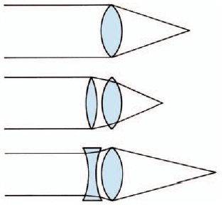
Figure 4-42 The effective local length of a camera lens can be decreased by adding a positive supplementary lens (center), and increased by adding a negative supplementary lens (bottom).
If the lenses are separated by a space (d), use the following formula:

Supplementary lenses are commonly calibrated in diopters, where the power in diopters equals the reciprocal of the focal length in meters, or D = 1/ƒ To convert from diopters to focal length, use the formula ƒ = 1/D. For example, with a 2-diopter lens, ƒ = 1/2 meter or 500 mm. With a 4-diopter lens, ƒ = 1/4 meter or 250 mm. An advantage of using diopters is that the power of the combination of a camera lens and a supplementary lens is the sum of the individual diopters, or Dc = D + Ds.
Adding a positive supplementary lens in effect reduces the focal length of the camera lens, but does not convert it into a wide-angle lens. Therefore, the covering power of the combination may be insufficient to permit use with distant scenes. Keeping the combined lenses at the same distance from the image plane that the camera lens alone would be when focused on infinity will typically provide sufficient covering power. Figure 4-43 illustrates that when a camera is focused on infinity and a positive supplementary lens is added, the point of sharpest focus in object space moves from infinity to a distance of one focal length of the supplementary lens from the camera. Thus, to photograph a small object from a distance of 6 inches, sharp focus would be obtained with a 6-inch focal-length positive supplementary lens on any camera focused on infinity, regardless of the focal length of the camera lens.

Figure 4-43 Positive supplementary lenses enable cameras to focus on near objects without increasing the lens-to-film distance.
Adding a positive supplementary lens to a camera lens produces the effect of reducing the focal length of the camera lens.
When photographing small objects, there can be an advantage in using a supplementary lens rather than increasing the lens-to-film distance with the camera lens alone (when the camera has sufficient focusing latitude). The aberrations in normal-type camera lenses are generally corrected for moderately large object distances, but the corrections do not hold with small object distances and the corresponding large image distances. There is the additional advantage that the camera exposure does not have to be increased when the camera is focused on infinity and a supplementary lens is added. If 1:1-scale reproduction photographs were made with the two procedures, four times the camera exposure would be required using the camera lens alone with the increased lens-to-film distance (see Figure 4-44).

Figure 4-44 Making a 1:1-scale reproduction photograph by increasing the lens-to-film distance (center) requires a 4x increase in the camera exposure. Using a supplementary lens (bottom) requires no increase in exposure.
Special Supplementary Lenses
Multiple-element attachments are available to modify the image-forming capabilities of camera lenses. Some of these are not generally referred to as supplementary lenses but rather by terms such as extender (or converter), afocal attachment, and monocular attachment.
Extenders are negative lenses containing one or more elements that are used behind the camera lens to increase the focal length. They are commonly referred to as tele-extenders, as they are most effective when used with telephoto or other longer-than-normal focal length lenses and produce a telephoto effect with the addition of a negative lens behind the positive camera lens. A tele-extender will increase the focal length of whatever camera lens it is used with by the same factor, such as 2×, although some are variable to produce different factors.
Afocal attachments combine positive and negative elements having appropriate focal lengths and separation between them so that rays of light entering the attachment from a distant object point leave traveling parallel, as in a Galilean telescope. Since the attachment does not form a real image, it has no focal length, hence the name afocal. Afocal attachments do alter the focal length of the camera lens, however, increasing it when the positive component is in front of the negative component, and decreasing it when the negative component is in front of the positive component, as illustrated in Figure 4-45. With the camera lens focused on infinity and the afocal attachment added, focus can be adjusted for different object distances by changing the distance between the positive and negative elements. Changing the ratio of the focal lengths of the positive and negative elements alters the effect of the attachment on the focal length of the combination and, therefore, image size. The afocal attachment has no effect on the f-number of the camera lens.
Convertible Lenses
Convertible lenses are designed so that one or more elements can be removed to change the focal length. Removing a positive element or group of elements increases the focal length. Removing the part of a compound lens that is in front of or behind the diaphragm introduces other complications. Since the focal length and the lens-to-film distance are both increased with the removal of a positive component, the f-numbers will be affected and a separate set of markings must be provided. This differs from the addition of an afocal attachment, where the focal length is altered but the camera lens-to-film distance and therefore the f-numbers are unaffected.

Figure 4-45 Afocal attachments change the effective focal length of camera lenses without changing the lens-to-film distance or the f-number. A two-element telephoto attachment is shown in front of a camera lens, at the top; a wide-angle attachment is shown at the bottom.
Two different focal lengths can be obtained with convertible lenses by removing part of the lens.
Although multiple elements can be used in both components of a convertible lens to minimize aberrations, the photographer should not expect the same image quality when part of the lens is removed. If a component is removed from a convertible lens to obtain a longer focal length for the purpose of making portraits, for example, the loss of image sharpness at large diaphragm openings may be flattering rather than detrimental, and stopping the lens down will reduce any loss of sharpness. Disrupting the symmetry of the lens on both sides of the diaphragm by the removal of one component without introducing barrel or pincushion distortion presents the lens designer with a difficult problem.
A more recent variation of the convertible lens is the substitution of a different component. This procedure makes it possible to maintain a higher degree of aberration correction and to offer a greater variety of longer and shorter focal lengths at a lower price than for completely separate lenses with different focal lengths.
Zoom Lenses
From the photographer's point of view, the ideal solution to the problem of having the right lens available for every picture-making situation is to have one versatile variable focal-length lens. Lens designers have made excellent progress toward the goal of a universal lens with the zoom design. With a zoom lens, the focal length can be altered continuously between limits while the image remains in focus. The basic principle involved in changing the focal length of a lens can be illustrated with a simple telephoto lens where the distance between the positive and negative elements is varied, as illustrated in Figure 4-46. This change in position of the negative element would change the focal length (and image size and angle of view), but the image would not remain in focus. Other problems include aberration correction and keeping the relative aperture constant at all focal length settings. It should not be surprising that one of the early zoom lenses contained more than twenty elements, was large and expensive, and was not very successful in solving all of the basic problems. Better zoom lenses are now being mass produced with relatively few elements, because of design improvements.

Figure 4-46 Changing the distance between the positive and negative elements of a telephoto lens changes the focal length.
Two methods have been used for the movement of elements in zoom lenses. One is to link the moveable elements in the lens so that they move the same distance. This is called optical compensation because the mechanical movement is simple, but the optical design is complex and requires more elements. The other method is called mechanical compensation and involves moving different elements by different amounts, requiring a complex mechanical design. For the problem of maintaining a constant f-number as the focal length is changed, an optical solution is to incorporate the concept of the afocal attachment at or near the front of the lens so that the aperture diameter and the distance between the diaphragm and the film can remain fixed. An alternative mechanical solution is to use a cam that adjusts the size of the diaphragm opening as the focal length is changed.
There are also mechanical and optical methods for keeping the image in focus. The mechanical method consists of changing the lens-to-film distance, as with conventional lenses. The optical method involves using a positive element in front of the afocal component that is used to keep the relative aperture constant. The range of maximum-to-minimum focal length varies with different zoom lenses from less than 3:1 to more than 20:1, with the larger ranges found only on lenses for motion-picture and television cameras.
Digital Zoom
The zoom lenses we have discussed thus far are optical zoom lenses, meaning the position of individual lens elements or combinations of lens elements within the zoom lens are changed to enlarge the image captured on the image plane. However, many amateur digital cameras enlarge the image through the use of digital zoom.
Digital zoom functions by cropping the digital sensor in the camera when capturing the image. The data is then interpolated or “enlarged" back to the full resolution of the digital sensor. Using digital zoom, just as optical zoom, also decreases the angle of view of the digital image. This process is meant to simulate optical zoom. Often during this process image definition is lost.
If the camera saves the digital image in RAW format, using the digital zoom on the camera will produce the same result as capturing the image and then enlarging it with image editing software later. However if the camera saves the image using a lossy image compression, such as JPEG, digital cropping may give a superior result over manual cropping later. This can happen because the on-board software may perform the interpolation prior to saving the image.
Macro-Zoom Lenses
Zoom lenses generally were not made to focus on short object distances. In 1967, the first of a series of macro-zoom lenses was introduced. Macro-zoom lenses are designed to photograph small objects near the camera either by extending the conventional focusing range or by making a separate adjustment in the position of certain components for the so-called macro capability. Use of the term macro in this context is misleading, as most lenses of this type produce a maximum scale of reproduction no larger than 1:2. To date, none yields a scale larger than 1:1, which is considered the lower limit for the specialized area of photography called photomacrography.
Use of digital zoom will often result in the loss of image definition.
Macro Lenses
Normal-designed lenses that produce excellent quality images with objects at moderate to large distances may not perform well when used at small object distances. At scales of reproduction larger than 1:1, where the image distance is greater than the object distance, such lenses tend to produce sharper images when they are turned around so that the front of the lens faces the film. Macro lenses are small-format camera lenses especially designed to be used at small object distances. The important optical characteristic of macro lenses is the excellent image definition they produce under these conditions compared with normal-type lenses (see Figure 4-47). The lens designer's task of optimizing aberration correction for small object distances is made easier by removing the additional requirement to make the lens fast. Thus most macro lenses are two or three stops slower than comparable normal-type lenses. The implication that macro lenses are not suitable for photographing objects at larger distances is not entirely valid, however. Because of the slower maximum speed, the aberration corrections are not as sensitive to changes in object distance, and some photographers prefer to use a macro lens for general-purpose photography when a faster lens is not needed.
A zoom lens should keep the image in focus and keep the image illuminance constant as the focal length is altered.
Macro lenses are designed to produce better image definition than conventional lenses when used at small object distances.
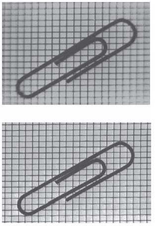
Figure 4-47 Photographs of a small object made with a normal-type camera lens (top) and a macro lens (bottom), both at the maximum aperture.
Spherical aberration is commonly used to produce the soft focus with soft-focus lenses.
Soft-Focus Lenses
Photographers typically want a lens to produce sharp images, but for some purposes a certain amount of unsharpness is considered more appropriate. Soft-focus lenses are sometimes labeled portrait lenses because they have been used so widely for studio portraits. However, soft-focus lenses have also been used extensively by other photographers, including pictorialists and even photographers doing advertising illustration, when certain mood effects are desired.
The soft-focus effect is generally achieved by undercorrecting for spherical aberration in designing the lens. Since spherical aberration is reduced as the lens is stopped down, the photographer can control the degree of unsharpness by the choice of f-number. To the discerning viewer, the effect produced with a soft-focus lens on the camera is not at all similar to that produced by defocusing the enlarger or diffusing the image while exposing the print with a sharp negative. Rays of light near the axis of a soft-focus lens form a sharp image, which is surrounded by an unsharp image formed by the marginal rays of light so that highlight areas in the photograph appear to be surrounded by halos (see Figure 4-48). If the same lens were used on an enlarger, the shadows in prints would be surrounded by dark out-of-focus images, except when making reversal prints from transparencies.

Figure 4-48 Photographs made with a normal-type camera lens (top) and a singleelement lens that was uncorrected for spherical aberration (bottom).
Anamorphic Lenses
An anamorphic lens produces images having different scales of reproduction in each of two perpendicular directions, usually the vertical and horizontal directions. It is common practice to think of one of the two dimensions of the image as being normal and the other as being either stretched or squeezed. Even before photography, some artists were experimenting with anamorphic drawings where, for example, it was necessary to view the image at an extreme angle for it to appear normal. Lens designers have long been familiar with the concept of anamor-phic lenses, but there was little demand for such lenses before the introduction of wide-screen motion pictures.
Motion-picture cameras equipped with anamorphic lenses have a wider-than-normal horizontal angle of view, but the extra width is squeezed by the lens to fit the conventional film format, which typically has an aspect ratio of 1.33:1. The projector, in turn, is equipped with an anamorphic lens that will stretch or unsqueeze the horizontal dimension to produce a picture with a higher aspect ratio (1.8:1, for example) and images that appear normal (see Figure 4-49).
Enlarger Lenses
The requirements for enlarger lenses are similar to those for a camera lens intended for copying, with aberrations minimized for small object distances, and in practice, the degree of correction can be expected to vary with the price for a given focal length. In the past, most enlarging lenses were designed for normal covering power with the expectation that the photographer would select a focal length about equal to the diagonal of the film format. Recent years have seen the increasing use of shorter focal-length lenses with larger angles of coverage to increase the range of scales of reproduction, and the range of image sizes that can be obtained with a given enlarger at the upper and lower limits of elevation.
Motion picture anamorphic camera lenses squeeze a wide angle of the scene onto standard-width film. The projector anamorphic lens unsqueezes the film image onto a wide projection screen.
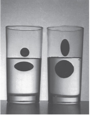
Figure 4-49 The water-filled parts of the glasses function as anamorphic lenses to stretch the images horizontally. Two stretched images of the penny on the left were rotated 90° and placed on the glass on the right where the bottom one was stretched back to a circular shape by the water. With wide-screen cinematic photography, the anamorphic camera lens squeezes a wide angle of the scene onto normal-width film, and the anamorphic projector lens stretches or unsqueezes the image to fit a wide projection screen.
The introduction of variable focal-length enlarger lenses followed years behind widespread use of variable focal-length lenses for motion-picture cameras, television cameras, small-format still cameras, and slide projectors.
Four types of lens shortcomings are related to (1) image definition, (2) image shape, (3) image illuminance, and (4) image color.
Lens Shortcomings
The geometrical drawings used to illustrate image formation in preceding sections imply that the lenses form perfect images. This is not the case, of course. Actually, there is no need for such perfect images in the field of pictorial photography, where photographs tend to be viewed from a distance about equal to the diagonal, and, as noted earlier, circles of confusion up to a certain maximum size are perceived as points. This tolerant attitude does not apply to photographs viewed through magnifiers or microscopes to extract as much information as possible, or even pictorial photographs that are enlarged and cropped in printing. Lens shortcomings can be subdivided into four categories: those that affect image definition, image shape, image illuminance, and image color.
The diffraction-limited resolving power of a lens can be calculated by dividing a constant by the f-number.
Practical lens tests done by examining photographs made with the lens are systems tests rather than lens tests.
Diffraction
Diffraction is the only lens aberration that affects the definition of images formed with a pinhole. According to the principles of geometrical optics, which ignore the wave nature of light, image definition will increase indefinitely as a pinhole is made smaller. In practice there is an optimum size, and image definition decreases due to diffraction as the pinhole is made smaller. The narrow beam of light passing through the pinhole from an object point spreads out in somewhat the same manner as water coming out of a nozzle on a hose, and the smaller the pinhole the more apparent the effect.
Similarly, the definition of an image formed by an otherwise perfect lens would be limited by diffraction. Some lenses are referred to as diffraction-limited because under the specified conditions they are that good. Using resolution as a measure of image definition, the diffraction-limited resolving power can be approximated with the formula R = 1,800/N, where R is the resolving power in lines per millimeter, 1,800 is a constant for an average wavelength of light of 550 nm, and N is the f-number. Thus a lens having minimum and maximum f-numbers of f/2 and f/22 would have corresponding diffraction-limited resolving powers of 900 and 82 lines/mm. If the resolution is to be based on points rather than lines, the formula is changed to R = 1,500/N (see Table 4-2).
Lens Testing
Photographers who inquire about testing a lens are commonly advised to do so by making photographs of the same type that they expect to be making with the lens in the future, and to leave the more analytical testing to lens designers, manufacturers, and others who have the training and the sophisticated equipment necessary for the job. It makes sense that a photographer should not worry about shortcomings in the imaging capabilities of a lens if the effects are not apparent in photographs made with the lens. On the other hand, many photographers use their normal lens in a variety of picture-making situations, and certain lens shortcomings may appear in one photograph and not in another. Thus, the subject matter and the conditions for even a practical test of this type must be carefully controlled.
To test for image definition, the following are required:
1.The subject must conform to a flat surface that is perpendicular to the lens axis and parallel to the image plane.
2.The subject must exhibit good detail with local contrast as high as is likely to be encountered, not of a single hue such as red bricks or green grass.
3.The subject must be large enough to cover the angle of view of the camera-lens combination at an average object distance.
Table 4-2 Diffraction-limited resolving power vs. f-numbers. (The underlined rows identify the f-numbers that would produce the same diffraction-limited resolving power of 14 lines/mm on 8 × 10-inch prints made from five different size negatives
| F-Number | l/mm | Film size | Adjusted for 8 × 10 Print |
| 1800
R-- F - number |
|||
| f/1 | 1800 | ||
| f/1.4 | 1286 | ||
| f/24 | 900 | ||
| f/2.8 | 643 | ||
| f/4 | 450 | ||
| f/5.6 | 321 | ||
| f/8 | 225 | ||
| f/11 | 160 | ||
| f/16 | 112 | 1-1½ | 112/8 = 14 |
| f/22 | 80 | ||
| f/32 | 56 | 2¼ | 56/4 = 14 |
| f/45 | 40 | ||
| f/64 | 28 | 4 × 5 | 28/2 = 14 |
| f/90 | 20 | ||
| f/128 | 14 | 8 × 10 | 14/1 = 14 |
| f/180 | 10 | ||
| f/256 | 7 | 16 × 20 | 7/0.5 = 14 |
| f/360 | 5 |
Note: 1,500 used for points; 1,800 for lines.
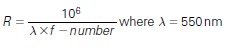
4.The subject must also be photographed at the closest object distance likely to be used in the future.
5.Photographs must be made at the maximum, minimum, and at least one intermediate diaphragm opening.
6.Care must be taken to be certain that the optimum image focus is at the film plane, which may require bracketing the focus.
7.Care must be taken to avoid camera movement, noting that mirror action in single-lens reflex cameras can cause blurring of the image, especially with small object distances or long focal length lenses. Outdoors, wind can cause camera movement.
If the same subject is to be used to test for image shape, it must have straight parallel lines that will be imaged near the edges of the film or sensor to reveal pincushion or barrel distortion (see Figure 4-50). If it is also to be used to test for uniformity of illumination at the image plane, it must contain areas of uniform luminance from center to edge. Tests for flare and ghost images require other subject attributes. We can conclude that a practical test cannot be overly simple if it is to provide much information about the lens. In any event, evaluation of the results is easier and more meaningful if a parallel test is done on a lens of known quality for comparison.

Figure 4-50 Simulates barrel distortion image. Note that the distortion does not affect radial subject lines—straight subject lines that intersect the lens axis, such as the horizon line and the center vertical line. (Photograph by Brandyn Balch, Photojournalism student, Rochester Institute of Technology.)
Practical tests such as these are not really lens tests, but rather they are systems tests, which include subject, lens, camera, film, exposure, development, the enlarger, and various printing factors. In the case of a digital camera system, test factors examined would be the subject, lens, camera, digital sensor, on-board processing, and whatever output device would be used, such as a monitor, ink jet or laser printer. The advantage that such tests have of being realistic must be weighed against the disadvantage that tests of a system reduce the effect of variations of one component, such as the lens, even if all the other factors remain exactly the same. For example, if two lenses having resolving powers of 200 and 100 lines/mm are used with a film having a resolving power of 100 lines/mm, the resolving powers of the lens-film combinations would be 67 and 50, using the formula 1/R = 1/RL + 1/Rf. Thus, only dramatic differences between lenses will be detected easily in the photographs.
The influence of other factors in the system can be eliminated by examining the optical image directly, either on a finely textured ground glass or by removing the ground glass and examining the aerial image. A good-quality magnifier or low-power microscope should be used. An artificial star, made by placing a lightbulb behind a small hole in thin, opaque material, is commonly used to check image definition by noting how the image deviates from an ideal point image. Since the ideal is seldom approximated closely, it is better to evaluate a lens by comparison with a lens of known quality than by judging it alone. By placing the artificial star at an appropriate distance on the lens axis, the effect of stopping down on spherical and longitudinal chromatic aberrations can be seen. The chromatic aberration can be removed by placing a green filter behind the hole to study spherical aberration alone. Moving the star laterally so that the image appears near a corner will reveal off-axis defects, including coma and lateral chromatic aberration.
Resolving power has been a widely used but controversial method of checking image definition. The testing procedure is simple. The lens is focused on a row of resolution targets that contain alternating light and dark stripes and that are placed at a specified distance from the lens (see Figure 4-51). The separate targets are arranged so that the images fall on a diagonal line on the ground glass or film plane with the center target on the lens axis, and oriented so that the mutually perpendicular sets of stripes constitute radial and tangential lines. The aerial images are examined through a magnifier or microscope of appropriate power, and the smallest set of stripes that can be seen as separate “lines” is noted for each target. Resolving power is the maximum number of light-dark line pairs per millimeter that can be resolved.

Figure 4-51 USAF Resolving-power target.
Critics of resolving power note that different observers may not agree on which is the smallest set of stripes that can be resolved, and that in comparing two lenses, photographs made with the lens having the higher resolving power sometimes appear to be less sharp. In defense of resolving power, it has been found that observers can be quite consistent even if they don't agree with other observers. Consistency makes their judgments valid on a comparative basis such as between on-axis and off-axis images, images at two different f-numbers, and images formed with two different lenses. It is appropriate to make comparisons between lenses on the basis of resolving power as long as it is understood that resolving power relates to the ability of the lens to image fine detail rather than the overall quality of the image.
Electronic methods have largely replaced visual methods of testing lenses in industry. The equipment required is complex and expensive but it is capable of providing comprehensive and objective data quickly. The results are commonly presented in the form of modulation-transfer-function curves in which the input spatial frequency is plotted as cycles per millimeter on the horizontal axis against output contrast as percent modulation on the vertical axis. Representative curves for three different lenses, two having imaging shortcomings, are shown in Figure 4-52, where lens B has higher contrast in the high-frequency (fine detail) areas but lower contrast in the low-frequency (coarse detail) areas than lens C. The accompanying pictures illustrate that a photograph in which fine detail is better resolved may appear less sharp because of the lower contrast in the larger image areas.
Resolving power is not a reliable indicator of the appearance of sharpness of photographic images.
Camera flare light reduces the contrast of photographic images, especially in shadow areas.
Testing Flare
Optical images formed with lenses are always less contrasty than the scenes being photographed because of the effects of flare light. Antireflection lens coatings are effective in reducing the proportion of light reflected from lens surfaces and increasing the proportion of light, transmitted, but they only reduce flare light, not eliminate it. In practice, flare light that falls on film or the sensor in a camera is a combination of lens flare and camera flare, and the amount of flare light can vary greatly with a given lens, depending upon the distribution of light and dark tones in the scene, the lighting, the interior design of the camera, and whether or not a lens shade is used. Thus, flare tests can be conducted with the lens in a laboratory where a standard test target is used and the effects of the camera are eliminated, or they can be conducted with the lens on a camera with a representative scene or a variety of scenes.
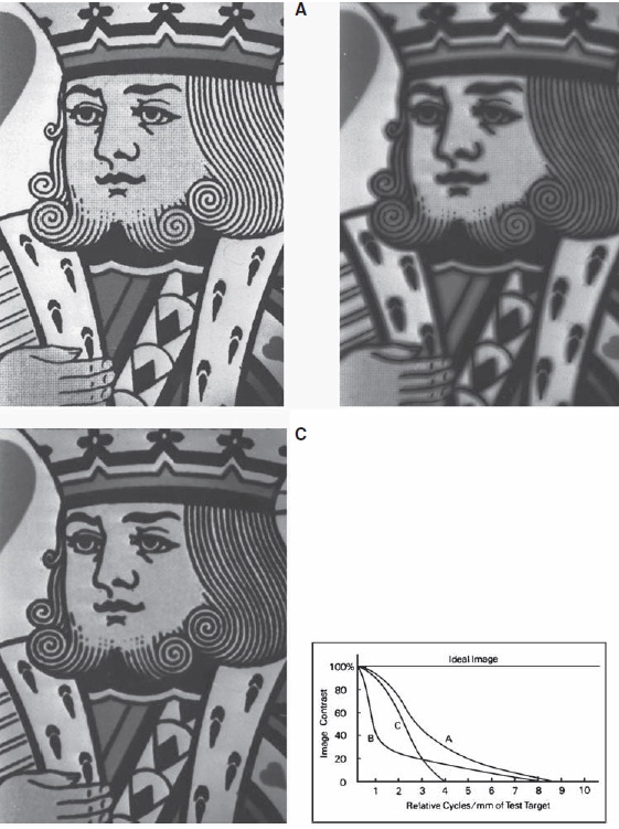
Figure 4-52 Prints made from a copy negative with three different lenses, and representative modulation transfer function curves. Lens A was a high-quality enlarging lens. The lens B image shows a large loss of contrast in the intermediate frequencies, while the lens C image shows the largest loss in the high frequencies. Lens B would score higher on a resolving-power test even though photographs made with lens C tend to appear sharper because of the higher contrast of the intermediate-size tonal areas.
Flare light can be specified in various ways—as a flare factor, as a percentage of the maximum image illuminance, and graphically as a flare curve. The flare factor is defined as the scene luminance ratio divided by the image illuminance ratio. The flare factor can most easily be determined with a large-format camera and an in-camera meter of the type where a probe can be positioned to take readings in selected small areas such as a highlight and a shadow. If the image illuminance ratio is 80:1 with a scene having a luminance ratio of 160:1, the flare factor is 160/80 = 2. Flare factors are typically between 2 and 3, but they can be much higher.

Figure 4-53 A black hole in a neutral test card surrounded by a gray scale, used to determine the flare factor in a given situation.
An opaque black card placed in front of a large transparency illuminator in an otherwise darkened room can be used to determine the percentage of flare light by dividing an illuminance reading of the image of the black card by an illuminance reading of the image of the transparency illuminator. A white surface and a black hole can be placed in any scene and used in the same way, where the black hole is a small opening in an otherwise light-tight enclosure painted black on the inside (see Figure 4-53). Standard test targets and simple procedures are available for the routine determination of the percentage of flare with process cameras in the graphic arts field where flare levels above 1.5% are considered excessive. With a normal scene having a luminance ratio of 160:1, a flare level of 1.5% corresponds to a flare factor of 2.4.

Figure 4-54 Flare curves prepared by taking meter readings at the film plane of the image of a gray scale with white, gray, and black backgrounds. The straight broken line represents the complete absence of flare light.
Flare curves can be prepared in various ways. One method is to place a step tablet or gray scale, with an appropriate surround, in front of a large-format camera, measure the relative illuminance of each step of the image with an in-camera meter, and plot log relative illuminance on the vertical axis vs. log relative luminance (that is, 1/density) of the original on the horizontal axis (see Figure 4-54).
Lens hoods help reduce flare.
REVIEW QUESTIONS
- If a pinhole aperture is used on a view camera in place of the lens, increasing the pinhole-to-ground-glass distance results in . . .
- an increase in the image size
- a decrease in the image size
- no change in the image size
- Diffraction causes the greatest degradation of the pinhole image when . . .
- Anamorphic pinhole images can be obtained by using . . .
- two pinholes, side by side
- a rectangular pinhole aperture
- crossed slits at different distances from the film
- anamorphic film
- The focal length of a lens is the distance from the . . .
- film to the lens
- principal focal point to the back nodal point
- front nodal point to the back nodal point
- subject to the lens
- The image distance that produces an in-focus image for an object located 300 mm from a 200-mm lens is . . .
- 200 mm
- 300 mm
- 400 mm
- 600 mm
- 800 mm
- Image size is . . .
- directly proportional to focal length
- directly proportional to focal length squared
- inversely proportional to focal length
- inversely proportional to focal length squared
- Two objects of equal size are located at distances of 10 feet and 20 feet from a camera. If the image of the nearer object measures 1 inch in the photograph, the image of the farther object will measure . . .
- 1/4 inch
- 1/2 inch
- 1 inch
- 2 inches
- 4 inches
- When a camera is moved farther away from a subject, the perspective . . .
- becomes stronger
- becomes weaker
- is unchanged
- The image of a distant building formed with a 90-mm focal length lens on a 4 × 5-inch view camera is 1-inch tall. To obtain an image that is 3 inches tall with the camera in the same position, it would be necessary to substitute a lens with a focal length of . . .
- 30 mm
- 60 mm
- 135 mm
- 180 mm
- 270 mm
- The recommended procedure for selecting the lens and the camera position for a photograph when perspective is an important factor is to select the . . .
- lens first, then the camera position
- camera position first, then the lens
- The "correct" viewing distance for an 8 × 10-inch print made from a 35-mm negative exposed with a 50-mm focal-length lens is approximately . . .
- 50 mm
- 8 inches
- 10 inches
- 12.8 inches
- 16 inches
- The heads near the left and right edges of a group portrait appear to be abnormally broad. This unnatural shape is associated with . . .
- barrel distortion
- pincushion distortion
- curvature of field
- the wide-angle effect
- the balloon effect
- The largest circle that will appear as a point on a print viewed at the standardized viewing distance is generally considered to have a diameter of approximately . . .
- 1/50 inch
- 1/100 inch
- 1/200 inch
- 1/400 inch
- 1/800 inch
- A definition of hyperfocal distance is
- the nearest distance that appears sharp when the camera is focused on infinity
- the distance from the lens to the film when the camera is focused on infinity
- one-half the distance to infinity when the lens is one focal length from the film
- the distance between the nearest and farthest objects that appear sharp
- A lens has a maximum aperture of f/2.0 and a minimum aperture of f/16. At f/16, the depth of field (DOF) will be . . .
- 4 times the DOF at f/2
- 8 times the DOF at f/2
- 16 times the DOF at f/2
- 32 times the DOF at f/2
- 64 times the DOF at f/2
- The object distance at which the largest depth of field is obtained for a given lens and f-number is . . .
- infinity
- 1/2 the hyperfocal distance
- the hyperfocal distance
- 2 times the hyperfocal distance
- Two photographs are made with a 4 × 5-inch camera, the first with a 200 mm focal-length lens and the second with a 400 mm focal-length lens. If both photographs are made at the same f-number and with the camera in the same position, the depth of field in the first photograph will be . . .
- 2 times that in the second
- 4 times that in the second
- 8 times that in the second
- the same as that in the second
- Image shape is controlled by tilting or swinging . . .
- the lens (only)
- the back (only)
- either the lens or the back
- Td control both shape and sharpness of the image of an object, the photographer should control . . .
- sharpness with the back and shape with the lens
- sharpness with the lens and shape with the back
- both sharpness and shape with the back
- both sharpness and shape with the lens
- none of the above
- The plane of sharp focus is controlled by tilting or swinging . . .
- the lens (only)
- the back (only)
- either the lens or the back
- A 50-mm focal length lens produces a 1/2 mm diameter image of a full moon. To obtain an image with a diameter of 24 mm to completely fill the width of a 35-mm negative would require a lens having a focal length of
- 240 mm
- 480 mm
- 2400 mm
- 4800 mm
- Insufficient information provided
- A simple telephoto lens consists of . . .
- a positive element in front of and separated from a negative element
- a negative element in front of and separated from a positive element
- a positive element and a negative element with an adjustable space between them
- none of the above
- A valid reason for using a 90-mm focal-length wide-angle lens in preference to a 210-mm focal length lens of normal design on a view camera would be to obtain . . .
- a larger angle of view
- a smaller angle of view
- a shallower depth of field
- a larger circle of good definition
- A problem that would be encountered in using a 28-mm focal-length wide-angle lens of conventional design on a 35-mm SLR camera is inability to . . .
- focus on infinity
- focus close up
- use the focal plane shutter
- use the reflex viewfinder
- stop the lens down beyond f/8
- Adding a + 12-inch focal length supplementary lens to a 6-inch focal-length camera lens produces a combined focal length of approximately . . .
- 2 inches
- 3 inches
- 4 inches
- 9 inches
- none of the above
- A 35-mm camera that is equipped with a 50-mm focal-length lens is focused on infinity. A 50-mm positive supplementary lens is added to the camera lens. The camera is now in sharp focus for an object distance of
- 35 mm
- 50 mm
- 100 mm
- none of the above
- An advantage of a macro lens over a lens of normal design of the same focal length is . . .
- lower cost
- larger depth of field
- higher speed (smaller f-number)
- better definition with small object distances
- The only aberration that affects images formed with pinhole apertures is . . .
- spherical aberration
- diffraction
- coma
- curvature of field
- distortion
- The diffraction-limited resolving power for a 50-mm focal length lens on a 35-mm camera, at a diaphragm opening of f/2, is . . .
- 1,800 lines/mm
- 900 lines/mm
- 450 lines/mm
- 225 lines/mm
- In lens testing, resolving power is associated with . . .
- graininess
- sharpness
- detail
- overall quality