
Chapter 3
Strictly Digital
Photograph by Josh Shagam, Biomedical Photography Communications student, Rochester Institute of Technology
The invention of flexible roll film by George Eastman at the end of the nineteenth century had an enormous impact, not only on photography, but on our culture as well. Prior to that event, creating photographs had been the domain of professional photographers and very dedicated amateurs. That first Kodak “point and shoot” camera put photography into the hands of the masses. A hundred years later, digital imaging software has placed the darkroom on the desktops of the masses. With today's image-editing software, images can be created in a matter of hours that a master printer, several years ago, might have labored for days to accomplish.
Aliasing or a moire pattern is an interference pattern caused by undersampling a fine regular pattern.
Table 3-1 Common Acronyms
| Acronym | Definition |
| CCD | Charge-coupled device |
| CMOS | Complementary metal oxide semiconductor |
| DNG | Digital negative format introduced by Adobe |
| dpi | Dots per inch |
| DSC | Digital SLR camera |
| .jp2 | JPEG 2000 file formate |
| .jpeg, .JPEG, | File format (joint photographic |
| or .jpg | experts group) |
| LCD | Liquid crystal display |
| LZW | A lossless file compression |
| ppi | Pixels per inch |
| RAW | File format |
| SLR | Single lens reflex camera |
| .tif, .tiff, or | File format (tagged image file |
| .TIFF | format) |
Digital Camera
In many ways, a digital SLR camera (DSC) is the same as a film camera. Lenses are interchangeable, and shutters, view finders and apertures all work the same.
The differences start when a digital imaging sensor replaces the film. In most DSCs, the image sensor is smaller than a 35mm negative by one-half to one-fourth that of the 35 mm full frame, which results in a smaller angle of view. Digital technology is not restricted to the 35 mm format. Larger-format sensors referred to as digital backs are available for large-format cameras, although their use is still mainly by professionals because of their high cost.
The basic DSC structure consists of a lens, a shutter assembly, an image sensor, and an electronic subsystem. The electronic subsystem includes both analog and digital processing controls. The remaining elements are an LCD display, a memory card socket, and connection ports to communicate with a computer.

Figure 3-1 CCD sensor.
The optics used in a DSC lens are the same as those used for film cameras. However, the silicon used in the image sensor is sensitive to energy in the infrared region of the electromagnetic spectrum. Therefore, the addition of an infrared blocking filter in front of the image sensor is necessary to block energy in this part of the spectrum. Additionally, an optical low-pass filter is also placed in front of the image sensor to prevent moire patterns or aliasing in the image.
The imaging sensor in a DSC can be a charge-coupled device (CCD), a complementary metal oxide semiconductor (CMOS) sensor, or the new Foveon X3 sensor. CCDs are the most common sensor used especially in low-end point-and-shoot cameras. See Figure 3-1. However as CMOS technology has improved, these sensors are becoming more common. Early CMOS sensors suffered from large fixed-pattern noise that negatively affected image quality and were larger than CCD arrays. CMOS sensors are growing in popularity, however, as these problems have now been corrected, coupled with the lower power needed to operate a CMOS sensor than a CCD. At the time of publication, the newest top-of-the-line DSC cameras introduced by both Canon and Nikon use CMOS sensors.
The function of the DSC electronic subsystem is to convert the analog signal that is produced by the image sensor to a digital signal. This process is often referred to as AD conversion [analog to digital (A to D) conversion]. Other processing performed by the electronic subsystem includes such things as tone adjustments, gain control, and color separations.
The digital processing in a DSC takes the digital signal and further processes the data before writing it to the magnetic media card in the camera. This can include applying a white balance correction, a color space conversion, and applying tonal corrections. In addition, the resulting image can be compressed prior to writing if required.
Digital Image Quality
Three key factors determine the quality of a digital image. They are brightness resolution or bit depth, dynamic range, and spatial resolution.
Brightness resolution is the number of discrete levels of gray quantized through the electric subsystem when the image is converted from an analog signal into digital values. This determines how many gray levels the final image will have. An 8-bit image will have 28 or 256 gray levels. A 10-bit image would yield 1,024 gray levels and 12 bits would produce 4,096 gray levels. In a color system, a 24-bit RGB color image has three color channels with 8 bits of data per color. Therefore, there would be 256 levels of red, 256 levels of blue, and 256 levels of green.
It has been found that in applications, such as monitor display and hardcopy output, 5 bits per color is usually enough information to represent continuous-appearing color and tones. When using a digital camera, if the output image is a jpeg file format, the cameras will sample down the number of input levels and output images at 8 bits per color, which corresponds to a luminance ratio of 256 to 1.
A bit depth of 8 corresponds to a brightness resolution of 256.
Dynamic range is the maximum range of light levels that an image sensor can measure or capture. More precisely, it is the ratio of the maximum measurable light intensity (just at pixel saturation) to the minimum measurable light intensity that is just about the noise level present. As ISO speed increases in a DSC, so does the noise level. The higher noise level increases the value of the minimum digital count a camera can capture, therefore dynamic range is usually decreased for higher ISO speeds.
Dynamic range and bit depth are both measures of the tonal quality of an image, as distinct from resolution, but dynamic range measures the difference between the lightest and darkest tones that can be captured and bit depth measures the number of intermediate tones between the lightest and darkest tones that can be rendered.
Spatial resolution is measured in pixels present in an image and is determined by the number of photocells in an image sensor. With an area-array sensor (an array with the photocells arranged in columns and rows), it is measured by the number of photocells or pixels in the x and y dimensions. For example, Canon’s EOS-1 Ds Mark III has a maximum spatial resolution of 5,616 × 3,744 pixels.
An 8-bit image will have 28 or 256 gray levels.
The spatial resolution of a linear-array sensor (an array with just one row of photocells) is determined by the number of photocells in the line and the number of measurements made in the scanning direction. Most scanners or cameras that use a linear array sensor move it across the imaging area with a stepper motor. At each step, the output of the array is read out and sent through the electronic subsystem. The spatial resolution in the direction that the sensor is moved is equal to the number of steps that it takes to move across the image. If the sensor is 2,048 pixels wide and is moved 3,000 steps, and a sample is taken at each step, the resolution of the resulting image would be 2,048 × 3,000 pixels. One method of increasing spatial resolution with a given size of linear-array sensor is to reduce the step size to half a pixel width and to repeat the scan with the sensor shifted laterally half a pixel width. Another method is to electronically interpolate the data between pixel positions.
Dots per inch (dpi) is a measure of the printing resolution of a printer and describes the number of ink or toner drops in a linear inch.
Pixels per inch (ppi) is a measure of the resolution of a display, a scanner, or a digital camera
For near-photo image quality, a camera resolution of about 150 to 200 pixels per inch of the display print is needed. A 4 × 6-inch print would require a resolution of at least 600 to 900 pixels.
A megapixel is 1,000,000 pixels.
The resolution of slide and print scanners is expressed as pixels per inch (ppi) since the size of the scanning area is known. A 35 mm film scanner scans an area roughly 1 × 1.5 inch, and most consumer flatbed print scanners are designed to measure an area as small as a credit card up to legal document size of 12 × 17 inches. Many scanner manufacturers refer somewhat imprecisely to the resolution of their scanners in dpi (dots per inch), which should be reserved for describing certain types of output devices.
Many manufacturers will also state an “effective” resolution, which is a clue that they are not describing the actual optical resolution. Effective resolution usually means the resolution after interpolation (creating new pixels by averaging between sampled ones) to achieve a higher resolution.
The resolution of digital cameras is best expressed as the number of horizontal and vertical pixel measurements made by the sensor, such as 5,632 × 3,750. Many camera manufacturers advertise the total number of pixels (horizontal pixels multiplied by vertical pixels), which for the example here would be 211,200,000, which is shortened to 21.1 megapixels.
Artifacts
Artifacts are unwanted defects in a digital image. One common cause of artifacts is the result of insufficient spatial resolution to capture a particular type of scene. A scene with high-frequency information (rapid variations in intensity), such as a white picket fence may show gaps or variations in the width of the individual pickets if too few samples are taken to capture the information. The first generation of consumer digital cameras typically had sensors with resolutions of about 640 pixels by 480 pixels. Outdoor scenes taken with these early cameras often reproduced high-frequency areas, such as grass, as just square patches of green shades because there weren’t enough pixels to capture details as small as individual blades of grass. Or, as illustrated in Figure 3-2, the hair is not distinguishable in the low and medium sample rate images.
Aliasing, also referred to as stair stepping, is another form of artifact typically seen as jagged edges on diagonal lines. This type of artifact is seen especially along the arm in Figure 3-2 in the low and medium sample rate images. Most pixel-level artifacts become much less objectionable with higher sampling rates because the individual pixels are much smaller.
Pixel defects are another unavoidable type of artifact with digital sensors. Making a sensor that is totally free of defects is nearly impossible because of the large number of pixels. There are hot pixel defects, in which the pixel has a high dark-current noise, and there are dark pixel defects, in which the pixel has a lower response than surrounding pixels. Column defects are usually caused by pixels that interfere with the charge transfer process causing all or part of a column of pixels to appear dark.

Figure 3-2 Sampling resolution: low (left), medium (middle), and high (right)
Noise
The level of noise produced by the sensor also determines the final quality of a digital image. Noise appears as random variations in the brightness levels or colors and is usually more prevalent in the shadow areas of a scene. Noise is caused by a number of different factors. A sensor will generate some current even when not exposed to light. The electrons within the photocells can be excited to move by heat alone. Dark current, as this type of noise is called, is the result of surface states within the chip and is a function of temperature and time. Long exposures and high operating temperatures will increase the level of noise in the output signal.
For scientific applications such as astrophotography, a variety of cooling techniques are used to lower the sensor temperature to around -50° C, which reduces the dark-current noise. This also allows for integration times as long as 30 minutes. Cooling of this type obviously isn't practical for most digital camera applications. Exposures of longer than 1/3 of a second are generally not recommended for digital cameras because of the noise levels generated during exposures over that period of time. Other causes of noise include readout noise (created by the output preamplifier) and cosmic noise (caused by cosmic radiation), which increases with longer exposure times.
The nominal ISO rating of a digital camera is set by most manufacturers such that the black level is just above the point where noise becomes objectionable. Many manufacturers will offer several higher ISO settings from nominal as an option. A higher ISO rating allows an image to still be captured even though those images will generally have higher levels of noise. Signal-to-noise ratio is a measure of how much noise is present relative to the signal strength (see Figure 3-3).
The higher the signal-to-noise ratio, the better the image.
File Formats
Many different file format options are available in which to save digital images. DSCs will offer several format options. These almost always include a native RAW format and several JPEG options. Additionally some will offer TIFF as an option. When the image is moved to a computer, many more options are then available.
There are two basic approaches to saving digital data. The first is a lossless file format. This is one that preserves all the original data, so that when the file is opened at a later time, all the original digital counts are preserved. The second option is a lossy file compression format. This approach removes redundant data from the file to reduce the final file size, thus saving disk space. This can cause image quality loss, especially in areas of fine detail. Using a lossy file compression destroys the original data that were recorded by the camera. They can never be recovered.
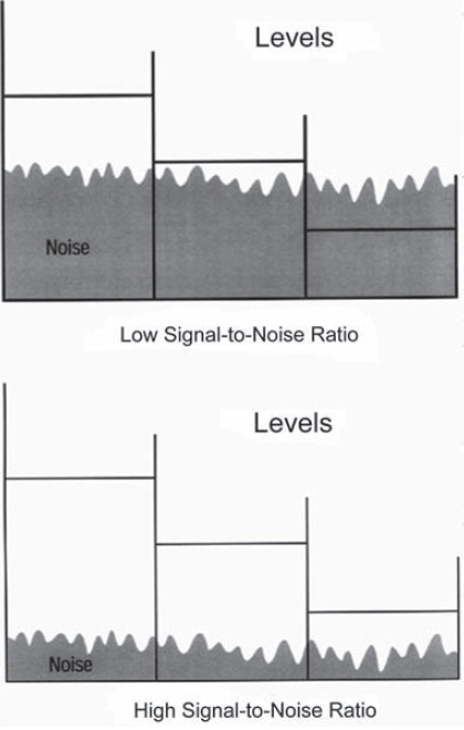
Figure 3-3 Signal-to-noise. The signal strengths, indicated by the heights of the three horizontal lines, are the same in both examples but the higher (gray) noise level in the top situation is stronger than the weakest signal and almost as strong as the second strongest signal.
RAW image files contain data from the image sensor that have minimal if any processing done to them. RAW file formats often save the data prior to interpolating to full RGB data. A RAW file is sometimes referred to as a digital negative. This is because, in principle, they are similar to a film negative. This should not be confused with the DNG file format, which is also referred to as digital negative. A film negative is used to create the final print, just as a RAW file is. In the darkroom printing process, a photographer can manipulate the final print made from the film negative using techniques such as dodging or burning or adjusting the contrast by selecting a particular grade of printing paper. A photographer can achieve all these same effects using image editing software and the RAW file.
RAW files have to be processed by a converter before they can be used. This is considered a drawback by some, as there is no standard RAW format. Manufacturers have their own individual proprietary formats. As improvements are made to the formats, older versions may become obsolete, making older files unaccessible to new software.
Adobe introduced the DNG (digital negative) file format in 2004. It is a royalty-free RAW image format and was developed in response to the demand from users for a common format. The DNG file format is gaining popularity and is supported by Hasselblad, Leica, Pentax, Ricoh, Samsung, Apple, and Sea & Sea. The OpenRAW file format introduced by the OpenRAW working group in 2006 is another attempt to unite all companies to use a common RAW format. Although both formats have some support from industry, many of the big camera manufacturers are continuing to use their own proprietary formats.
JPEG (Joint Photographic Experts Group) is a common compression format used in photography. JPEG is a standard format and is recognized by all image-editing software packages. There are two JPEG formats, the original JPEG format which has a file extension of .jpeg or .jpg. This format is widely used. The second is JPEG 2000, file extention jp2. JPEG 2000, provides options for both lossy and lossless compression of image data. When selecting the lossy compression option, the degree of compression or, in other words, the resulting quality of the output image can be selected by the user. This format is not as widely used yet.
A TIFF (tagged image file format) is a file format that is used for both line art and photographs. Just as with JPEG, TIFF is widely supported by most image editing software. TIFF is a lossless file format, but has the option to use a LZW compression. LZW is a lossless compression technique created by Abraham Lempel, Jacob Ziv, and Terry Welch in 1984.
Digital Image Processing
The first step in the digital-imaging chain is getting an image onto a computer, whether by scanning existing images, by photographing a scene with a digital camera, or by creating an image using software. Once in a digital format the image is now just a series of numbers that can be mathematically manipulated any number of ways. If the result isn't what you wanted, click on “Undo” and start over!
Every trick of the master printer's trade and some they never imagined can be accomplished with existing image-processing software. Adjusting tonal range, tonal placement, tonal contrast, color balance, color saturation, and sharpness are all easily accomplished with a few clicks of a mouse. Complex masks can be easily created, allowing these same adjustments to be made to just the selected portions of the image. Image defects such as dust and scratches can be easily removed with a technique called cloning. The cloning brush copies information from an adjacent area to replace the defect by effectively blending similar tones and textures over the defect. No more spotting and retouching prints! Retouch the image once digitally, and every print thereafter is free of those defects. Some image-editing programs now even offer automatic algorithms that search out defects such as dust, scratches, and red-eye, and attempt to fix these problems with little user intervention.
Image-editing programs use a variety of mathematical functions to perform different processes on an image such as analysis, pixel point processing, pixel group processing, frame processing, and compression.
Note: For the purpose of illustrating the following concepts of image processing, various tools and dialog boxes from Adobe's PhotoShop software were used, but many other packages provide very similar tools.
Histograms
Analysis of digital data can now start at the time of exposure. Digital cameras now can show the photographer a histogram of the digital data as soon as the image has been captured, allowing a photographer to determine if the exposure was correct. If not, the photographer can make an adjustment to the exposure and reshoot the image instantly.
A histogram shows the distribution of digital values for all of the pixels in the image area (see Figure 3-4). The bottom axis represents the entire grayscale from 0 to 255. The vertical lines represent the number of pixels or frequency of each value in the image. If the image is an RGB color image, a histogram can be viewed for each of the individual color channels as well.

Figure 3-4 Full-image histogram.
Viewing an image histogram provides a visual representation of the type of image that you have. A high-key image would have many of the pixels at the higher digital values to the right of the histogram, which is where highlight detail is. A low-key image would have many pixels at the left end of the histogram where the shadow detail is. An image with good dynamic range will have a histogram with values extending most of the way from 0 to 255. Having a large number of pixels at 0 or 255 would indicate that the image was either under- or overexposed.
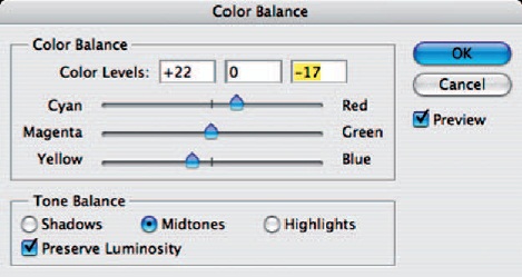
Figure 3-5 Color-balance tool. Color balance can be selectively adjusted for shadows, midtones, or highlights.
Pixel Point Image Processing
Pixel point processing is the most basic image-processing operation and can be used to correct images with contrast or color balance problems. Pixel point processing uses a mathematical function to map the original pixel values to new output values, lightening, darkening, or changing the contrast of an image. The simplest form of image remapping is called slide mapping. Adding or subtracting a constant value to all pixels in the image will alter the overall brightness. This has the effect of moving all the values in the histogram to the right or to the left, basically what a brightness control for a video screen does. The drawback to slide mapping is that if you add 50 to all pixel values, then all the pixels whose values were above 205 or higher will become 255 and highlight detail will be lost. Conversely, if you subtract 50 from all pixel values, then all pixels whose values were 50 or below will become 0 and shadow detail will be lost. Slide mapping should be used carefully because it is easy to permanently lose image data.
A constant value applied to only one of the color channels will change the overall color balance of the scene. The color-balance tool uses this technique. PhotoShop's color-balance tool also allows one to weight the value, applying it more toward the shadows, midtones, or highlights (see Figure 3-5).
The next type of mapping is stretch mapping. Stretch mapping uses multiplication or division by a constant to stretch or contract the tonal values over the histogram, which can be used to stretch a low-contrast image over the full range of values to produce normal contrast. The Levels tool does the math automatically. By moving the black point and white point control triangles under the histogram, you can stretch the values out over the range of 0 to 255 (see Figure 3-6). Complement mapping inverts all the values in the image: black becomes white, white becomes black, and gray values are mapped to their complementary tones above and below a middle gray.
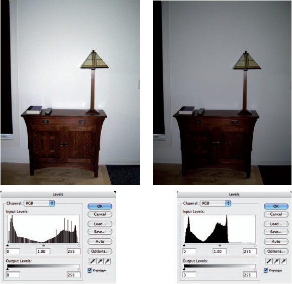
Figure 3-6 The Levels tool is used to apply stretch mapping, which controls image contrast.
The middle-gray triangle in the Levels tool is used to adjust gamma. It affects the midtones, while not changing the white or black point. Instead of applying a constant value, the midtones are changed using a Gaussian (normal) distribution, with greater amounts of change in the middle values and decreasing amounts toward the highlights and the shadows.
The Levels tool corresponds to different contrast grades of photographic paper.
Moving the middle-gray triangle to the left lightens midtones, and moving it to the right darkens midtones.
The Curves tool allows remapping of an image based on a drawn curve by changing the curve shape. A straight diagonal line results in no change, but by drawing an S-shaped curve the shadows can be darkened and the highlights lightened with less change to the midtones. This tool allows very fine control over gray-level distribution that is simply not achievable with the Levels tool. Clicking on an area in the image highlights that value on the curve.
Pixel Group Image Processing
In pixel group processing, used to create a variety of special effects, a mathematical function called a convolution uses the values of the surrounding pixels to determine a new value for each pixel (see Figure 3-7). As the matrix or kernel slides over each pixel in the image, the values of pixels falling within the matrix are multiplied by the factor in each cell of the matrix. The sums of that process are added together to create a new value for the center pixel. These new values are stored, creating a new image, so that previously processed pixels don't affect the current pixel. The sum of the factors in the matrix should equal 1 to maintain the same brightness levels in the new image.

Figure 3-7 Convolution filters use for a variety of special effects, including blurring and sharpening the image.
Blur and sharpening filters are two common examples of convolution filters. Several other filters that use this technique are the median filter, which is useful in reducing noise or halftone screen patterns in an image, and the emboss filter, which creates the effect of a bas-relief image with shadows and highlights along edges in the image.
Probably the most used filter in digital imaging is the unsharp mask filter. The unsharp mask filter is a sharpening filter. Whether using a digital system or a film-based system a blurry image cannot be made unblurry, however it can be sharpened. A sharpening filter provides an apparent increase in edge sharpness by increasing the contrast along edges. It is interesting to note that human eyes have a similar capability, by altering the sensitivities of the rod and cone sensors on opposite sides of image edges.
The unsharp mask filter is quite flexible, having three parameters that can be adjusted to meet the needs of any particular image. The three parameters are amount, radius, and threshold. The unsharp mask is not an edge detector; instead it locates pixels within an image that differ by a threshold value you have set. Once it locates pixels that exceed the threshold value, the lighter pixel is lightened and the darker pixel is darkened by the amount value set. The final value, radius, tells the software how to set the region to which each pixel is compared. Increasing this value increase the edge effects.
Caution must be exercised when using any sharpening filter. Oversharpening an image can produce halos around edges. See Figure 3-8.

Figure 3-8 The image on the right has been over-sharpened, creating a halo around objects and increasing the visibility of the noise.
Bicubic interpolation will produce the highest quality image when downsizing or upsizing an image.
Additionally, sharpening can also cause noise to become more apparent in an image, which can be easily seen in areas with little detail such as the sky. One common method to avoid this when sharpening color images is to only sharpen the red and the green data. The blue data are then either left alone or actually smoothed. The blue data will have the most noise present because of the lower sensitivity of silicon to blue wavelengths.
Frame Image Processing
Frame image processing is applying a function, such as rotation, scaling, and color-space transforms, to a region or the whole image. Rotations such as 90 or 180 degrees simply reorder the columns and rows of pixels in an image.
Scaling or resizing an image is another form of frame processing. There are many methods for performing tasks. When reducing the size of an image, the simplest method uses a technique called decimation. Decimation means not using all of the available pixels. If an image is reduced by 50%, half the pixels in each direction will be discarded, leaving just one-quarter the number of pixels. This method does not produce very good results.
The simplest method for increasing the size of an image is pixel replication, often referred to as “nearest neighbor.” In this method, if the image needs to be doubled in size, replication will take each pixel and duplicate it to create the new image. This method will cause the image to become increasingly more pixilated-looking because, in effect, it just enlarges each pixel. Edges will often be jagged in the resulting image
Interpolation is the preferred approach for both downsizing and upsizing images. This technique creates new pixels by calculating a new value based on the surrounding pixels. There are two algorithms used for interpolation: bilinear and bicubic. Bilinear is a medium-quality interpolation algorithm and uses four neighboring pixels to calculate the new pixel values. Bicubic is a very high-quality interpolation algorithm that uses 16 surrounding pixels in its calculations but as a result takes much longer to process.
Digital Printing
The choices available for creating pho-tographic-quality digital-color output are constantly growing. The options range from inexpensive desktop inkjet printers to room-size printers that utilize lasers to write directly onto photographic paper (and cost several hundreds of thousands of dollars). All digital printers do have one thing in common: a print engine that writes dots onto paper or some form of receiver material.
Continuous-Tone and Halftone Output
How the dots are created allows us to categorize printer output into one of two distinct categories, continuous tone or halftone. Continuous-tone digital printers produce output that is strikingly similar to the traditional color photographic process. Many digital printers are even printing on conventional color photographic materials.
Continuous-tone printers write individual image pixels directly to paper or film. The dots created are of varying density (usually 256 levels or>8 bits per color) and the dyes used are transparent. This allows one color to be placed directly on top of the previous color. The dyes combine to create a very wide range of colors. A printer using the three primary colors of cyan, magenta, and yellow (most continu-ous-tone printers don't use a black dye but instead create a process black by combining equal amounts of cyan, magenta, and yellow) is theoretically capable of reproducing more than 16.7 million colors. The color gamut of the dyes used will determine the actual number of colors that can be reproduced.
Halftone output is similar to that created by the large printing presses used in magazine and newspaper reproduction. Halftone printers create dots that are opaque and do not vary in density. Halftone dots, therefore, can't be placed on top of one another without obscuring the previous color. Each image pixel must be converted into a pattern of varying amounts of cyan, magenta, yellow, and black dots. These patterns of small dots blend in the eye and are perceived as various colors when viewed from a distance. This process is called halftone screening.
The computer brought radical changes to the halftone-screening process. The traditional method for screening a photographic image was to copy the photograph using a large-process camera. An exposure was made through a contact screen onto high-contrast sheet film, one exposure for each color. The contact screen was a sheet of film with a precisely exposed crisscross pattern of varying densities. A different screen was used for each color and had the crisscross pattern rotated at various angles, black at 45 degrees, magenta at 75 degrees, yellow at 90 degrees, and cyan at 105 degrees. These screens would break the image up into a series of dots of varying frequencies and sizes corresponding to the amount of that particular color in the image to be printed. The resulting high-contrast films would be used to expose the printing plates. The screens were angled to prevent moire patterns in the final image and resulted in the familiar rosette pattern of the halftone screen.
With the advent of the computer, the whole photomechanical screening process was eliminated. The computer could mathematically convert an image into screened dots and even write it directly onto the high-contrast films using printers such as the Linotype laser typesetter. Today, computers can even write directly to the printing plates themselves with units such as Heidelberg's digital direct-to-plate presses. New ways of screening images also became possible: stochastic or error-diffusion screening, for example, in which the dots are generated in random patterns that increase or decrease in frequency depending on the color and density of the image. This would have been extremely difficult to accomplish without the use of a computer. This technique is now widely employed by many inkjet printers and it significantly boosts the apparent resolution of a printer.
A printer having about 600 dpi can produce near-photoquality prints.
Continuous-Tone Printers
Printer resolution in dpi (dots per inch) does not correspond to pixel resolution. It is how close the printer can place ink droplets on paper.
The following are examples of some different types of continuous-tone printers. This is hardly a complete list but attempts to illustrate just some of the technologies available.
Film Recorders
The first devices adapted to computer output were those originally designed as hard-copy printers for analog video or television. In the mid-1980s manufacturers such as Polaroid, Beseler, and Dunn Instruments introduced film recorders that would allow print or film materials to be exposed by sending a video signal to a specially designed flat monochrome cathode-ray tube (CRT). A camera (often a standard 35-mm back with a flat-field lens) was pointed at this CRT within a light-tight housing, the shutter was opened, and the image was drawn line by line on the face of the CRT. To create a color image, a color filter wheel with red, green, and blue filters was utilized. The image would be drawn three times, once each for red, green, and blue color channels.
The second generation of film recorders were specifically designed for computer use and featured higher resolutions (2,000 lines or more) and digital interfaces. Instead of analog video, digital image files from digital scanners could now be processed using software to enhance the image and then output to film directly from the computer. It could then be printed conventionally. This was the only high-quality solution for several years.
Film recorders are still in wide use today, mostly in applications that require extremely high resolution and where turnaround time is not an issue. Some of today's high-end film recorders, such as the Symbolics and Management Graphics models, have resolutions of up to 16,000 lines and can output on film sizes from 35-mm to 8 × 10-inch sheet film.
Recently, devices that print directly to photographic paper have been making rapid in-roads into professional labs. This is largely due to their ability to print digital images directly to large paper sizes. Several different technologies are being used in these printers and are listed below.
Light-Emitting Diode (LED)
The LED printer, such as Kodak's Pegasus LED printer, prints directly onto special digital photographic paper using a small array of LEDs. The Pegasus printer is a roll-fed printer that can handle roll sizes up to 20 inches wide. The paper is fed into a drum where a vacuum pump pulls the paper tight against the inside of the drum. The drum will accommodate a 33-inch-long piece of paper, allowing a maximum 33 × 20-inch image to be printed.
The image is exposed by a small array consisting of four red, four green, and four blue LEDs mounted at the end of a counterbalanced arm. The arm spins on a spiral track at about 1,350 RPM. The LED lens assembly spins just above the paper's surface, writing the image as the arm travels down the length of the drum on the spiral track. After the image is written, the paper is advanced into an attached processor for development, and exits dry in about 6 minutes. LVT is another company manufacturing printers that utilize LED diodes for exposing photographic film and paper. Instead of the paper being drawn by a vacuum to the inside of a drum, the paper is wrapped around the outside of a drum. The output of the red, green, and blue diodes is combined to create a single spot that is then focused to write the image.
Laser Diode (Laser)
The Durst Lambda printer is one of the more popular digital printers on the market. Utilizing a series of laser diodes to write a digital image directly onto photographic paper, the Lambda printer can handle rolls of paper up to 50 inches wide, and it writes to the paper as it moves past the laser imager. As a result, much larger images can be written than the limits imposed by the circumference of a drum as with the LED printers.
Thermal Transfer
Another technology that started out as a video output device was thermal dye-diffusion printing. In the mid-1980s both Sony and Kodak introduced printers that produced a continuous-tone image from a video source using the thermal dye-diffusion process.
The thermal dye-diffusion process uses a two-part medium. The first part is a clear Mylar film material, called a donor ribbon, onto which consecutive transparent cyan, magenta, and yellow dye patches are coated using a process similar to gravure. The second part is a specially coated paper-based material called the receiver. The donor material resides on a spool driven by a motor. A thermal print head containing thousands of individually controllable resistive elements is used to heat the dyes on the donor material and thereby transfer the dye from the donor material to the receiver. The amount of dye transferred is controlled by varying the amount of current (and thus heat) sent to each of the resistive elements on the print head. Stepper motors drive the receiver paper and the donor material past the resistive head. One color patch is printed at a time and the paper is rewound back to precisely the same starting point each time so that the next color is placed in registration with the preceding one.
It is important to note that the dyes are transparent and that the density can be varied up to 255 different levels for each color. Because the dyes are transparent, the color dots are placed on top of one another, combining to create any of the 16.7 million theoretically possible colors in a 24-bit image.
Halftone Printing Technologies
Thermal Wax Transfer. A similar technology, known as thermal wax transfer, appeared around the same time as dye diffusion. Opaque wax colorants are coated in patches onto a ribbon like those used in dye diffusion. The thermal head melts the wax and transfers it to the paper. One advantage of thermal wax was that it did not require a special receiver material; plain paper could be used. The quality of the images produced was limited by the fact that it was a fairly low-resolution (300 dpi) halftone device. As a result, it was generally used as an output device for business graphics or proofing.
Phase-Change. Actually considered a form of inkjet, phase-change technology has similarities to the thermal wax printer. Instead of wax-based dyes coated on a thin transport ribbon, phase-change devices use a solid wax that is melted and then sprayed via nozzles onto the paper—hence their nickname “crayon spitters.” Tektronix is the major manufacturer of both wax-transfer and phase-change technology printers.
Electrophotographic. This technology initially developed for copiers found its way into desktop printers with the introduction of the laser printer in 1985. A laser, directed via a spinning mirror, is used to alter the magnetic charge on a rotary drum. Toner particles are then attracted to these areas of the drum, and as the drum rotates into contact with the paper the toner particles are transferred to the paper. The paper is transported through a pair of heated rollers, fusing the toner particles to the paper. The color process adds cyan, magenta, and yellow toners to the process and requires exposing the electrostatic drum once for each color.
Gravure, from the French word graver meaning to engrave. It is a process for quality printing using etched plates or cylinders.
Prints made with fused toner are relatively inexpensive per sheet compared to most other technologies discussed here. However, they do not hold up well over time.
Inkjet Printers. Inkjet technology is one of the more rapidly changing technologies because of the enormous amount of development dollars being spent on it. The primary reason is because it is one of the few technologies affordable enough for the home consumer.
The Image Permanence Institute researches preservation of recorded information, including photographs Their website is http://www.imagepermanence institute.org/.
Thermal or Bubble Jet. The most common inkjet technology is the thermal or bubble-jet system found in printers made by companies such as Canon and Hewlett-Packard. This technology is referred to as drop-on-demand (DOD). Each ink cartridge contains a series of tiny nozzles and an electrical connection to the printer. The ink is routed into a series of individual chambers, each with a tiny resistive heating element. A pulsed current applied to the heating element heats the ink until it vaporizes, causing a bubble to form. The expanding bubble forces the ink through the small opening in the chamber and sprays it toward the paper. The vacuum created in the chamber draws more ink into the nozzle.
The cost of replacement cartridges as a result is relatively high with this type of technology. When the ink cartridges are replaced, the head technology is replaced as well, even though it may still have much useful life left.
Ink stability has been a major problem with most desktop inkjet printers. Most inkjet prints have a display life measured in months or, at best, a few years. New waterproof inks and pigmented inks are beginning to become available for the larger-format printers, and are trickling down to the desktop printers as well.
Piezoelectric. Piezoelectric inkjet printers, instead of using a heating element to force the ink out of the nozzle, use a small piezoelectric crystal that expands when a current is applied. The piezoelectric jet is like a small electromechanical pump and can deliver a very small amount of ink very precisely. Used by Epson in their line of desktop printers, piezoelectric technology is currently capable of resolutions up to 1,440 dpi. The drawback to this technology has been printing speed, but advances are being made with each new generation of printer.
The inks available from Epson fare little better than those of most desktop inkjet printers. In response to the popularity of the Epson printers (because of their photo-quality output), a number of third parties have begun providing alternative inks, cartridges, and papers that promise archival-quality prints.
Continuous-flow. Continuous-flow or “hertz” inkjet printers pump a continuous stream of electrically charged ink droplets (more than 4 million per second) at the paper. A magnetic field is used to control ink placement on the page; unused ink is directed to a recovery reservoir.
Continuous-flow inkjet printers are available for several distinctly different types of applications. The highspeed, low-resolution variety are used in applications such as product identification, personalized direct mail, and addressing catalogs and magazines.
The high-resolution, low-speed printers, such as the IRIS series by Scitex, are used for proofing and fine art printing. IRIS printers can produce multiple spots per dot and can achieve effective resolutions of up to 1,800 dpi. In part because of the great number of paper surfaces that it can print on (especially heavier weight, fine art water-color papers), the IRIS has become one of the most popular printers for fine-art reproduction. These prints are often referred to as Giclee (pronounced ghee-clay), which is really just a fancy French name for inkjet. Giclee prints made using the latest archival inks have been tested to have a display life of up to 75 years and perhaps even longer.
Archival Considerations
New inks and receiver materials are coming to market every day. To keep up with any of these new technologies, there are newsgroups and forums available via the Internet where the latest information can be shared and discussed with others. One Web site that will prove invaluable is that maintained by Henry Wilhelm of Wilhelm Imaging Research Inc. at http://www.wilhelm-research.com.
Henry Wilhelm is considered the leading expert on print permanence and is constantly testing the display life of new photographic papers, inks, and inkjet papers. The Web site is frequently updated to reflect the latest testing results.
REVIEW QUESTIONS
- The light recording technologies used by most digital cameras and scanners is …
- ADC
- CAD
- CCD
- EPS
- The yield of a 10-bit ADC in terms of gray values is …
- 4,096
- 1,024
- 256
- 128
- The advantage of having a sensor with twelve or more bits is similar to films with …
- higher ISO speeds
- greater exposure latitude
- less graininess
- increased sharpness
- Aliasing is most pronounced in an image with edges that are …
- horizontal
- vertical
- diagonal
- Most commercially available silicon CCDs are …
- frontside-illuminated
- backside-illuminated
- topside-illuminated
- splitside-illuminated
- The most common type of area array CCD is …
- progressive scan
- frame transfer
- pixel-scan transfer
- interline transfer
- One disadvantage of a frontside-illuminated CCD is its poor spectral response in the …
- blue region
- blue-green region
- blue-red region
- green-red region
- High-end drum scanners typically use …
- CCD sensors
- vertical pixel arrays
- photomultiplier tubes
- horizontal pixel arrays
- The simplest form of image remapping is called …
- stretch mapping
- complement mapping
- slide mapping
- pixel point mapping
- The most affordable type of printer for home consumer use is …
- bubble jet
- electrophotographic
- thermal wax transfer
- inkjet
- laser