
3 The video camera
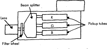
Video cameras are simply devices which can convert the images we see into electrical images that can be recorded onto magnetic tape. The two main ways of doing this are either by using cathode ray tubes (tube cameras) or charge coupled devices (CCD cameras). Tube cameras are now almost exclusively redundant, although some countries will still have the old technology’ (Figure 3.1). The advancing micro electronics industry has given us lighter, smaller, better, more reliable and more sensitive imaging technology. As with computer technology these CCD devices are known as chips. Hence three-chip cameras.
Figure 3.1 Three-tube camera shown for comparison
All cameras have a lens, which helps to control and shape the image achieved. The lens will have at least two controls, focus and aperture (or iris).
The focus allows for change of distance from the subject to the camera, to keep the significant part of the image clear. The aperture controls the amount of light getting into the camera and so is crucially connected with the effect of lighting. A variable size hole (called the iris) allows more or less light in. The numbers (f-numbers) on it are in a scale such that each step halves (or doubles) the amount of light let in. Perhaps confusingly the numbers of this scale get smaller the bigger the hole is, so, for instance, f4 lets in twice as much light as f5.6.
Immediately behind the lens the image is broken into three separate colours – called primary colours – red, green and blue. The amounts of these are measured. The right amounts of red, green and blue will result in white. If the percentage of these colours is altered, the result will not be interpreted as white.
The three colours can either go into one pickup (tube or CCD), by means of a specially striped filter, or into three separate ones (one for each colour) depending on the design of the camera.
Single-chip cameras (Figure 3.2), whilst lighter and cheaper, cannot resolve such fine detail, nor keep such good colour saturation as three-chip equivalents (Figure 3.3), since the striped filter necessarily imposes a limit.
Figure 3.2 (left) Single-chip camera

Figure 3.3 Three-chip camera

Between the back of the lens and the pickups is a colour balance filter wheel which, by passing the image through one of a set of coloured glass discs, provides the first (coarse) correction of the response of the camera to different coloured lighting.
It is because the actual colour temperature of the light coming in through the lens is split into red, green and blue and then measured as percentages that we get images of the ‘wrong’ colour. It is these glass discs that are switched to 5,500 or 3,200°K to give a starting point for the correct white balance.
CCDs are physically robust, and much more tolerant of extreme light levels than tubes. Being smaller, and less hungry of voltage they allow cameras to be more compact, and less demanding of scarce battery power (on location) than their old tube equivalents. From a lighting point of view they also have the considerable advantage of being more sensitive (thus needing less light to deliver a good image) and having a wider contrast ratio (thus being more tolerant of variation between dark and light parts of the scene).
In a naturally lit bright scene, there is a great variation in level between the brightest and the darkest portions. This difference is known as the contrast level of the scene. Our eyes can take in a tremendously wide contrast range, but video cameras are much more limited.
In order to capture a good video image, the contrast level between the brightest and the darkest needs to be limited, but not to such an extent that it is eliminated. We can’t do much about the brightest levels outdoors, in natural light, but may need to make a decision to allow the darkest to appear totally black, or whether to add a little light in the shadow areas, to reduce the contrast level, and thus allow the camera to ‘see’ into the darker areas.
Location work indoors, or in a studio, needs very careful setting of these levels of light and dark to obtain the correct balance. Artificial lighting, therefore tends to start with a fairly high level of light overall, with the areas we want brighter given just a little bit more illumination to make them appear brighter.
The human eye and the video camera
It will help to understand the subtleties of lighting if we consider the differences between the camera and our own eyes.
The camera is optically very similar to our eye, but electrically very different. The eye has a lens, enclosed in the eyeball, and we use muscles to alter the shape of the lens thus altering its focal length. We have an iris, a variable sized opening, to control the amount of light entering the eye. The image is produced on the light sensitive rear surface called the retina. The nerves attached to the retina send electrical signals to the brain, which allows us to ‘see’.
Like any optical system the image is inverted and the brain has learnt to interpret it as the right way up. We have also learnt to interpret what we see in the way of colour, but the brain actually misleads us. Because of the sensitivity of the eye to colour not all colours are seen equally brightly. Although the primary colours of red, green and blue will make white our eyes need 30% red, 59% green and 11% blue to mix the colours to white. Because we have learnt what white is our brain will tell us that an object is white even when the colour temperature of the lighting has actually altered the colour reflected. This is noticeable at sunrise or sunset for instance. It is also true in a video studio, where the colour temperature of the lighting is such that a white shirt is actually slightly red.
On the other hand a camera interprets the quantities of light it sees as equal percentages of red, green and blue which do not add up to ‘our’ white unless adjustments are made to alter those percentages. This is the reason that a ‘white balance’ must be done every time the colour temperature of the light alters.
Unlike our eyes, the camera lens can be altered to give a wide angle or a telephoto view of the world. We need additional lenses, such as binoculars, to achieve this distortion of the viewpoint.
Because we have two eyes, with a fixed distance between them, we see things from two angles. This allows us to see depth, the distance between an object and its background, we see three dimensionally. The camera only has one angle of view and sees in two dimensions. It is a function of the lighting to suggest depth.
Lighting operators must be aware of contrast ratio. Contrast ratio is the relative level between the lightest and the darkest part of a scene. Our eyes can interpret enormous ratios of light and dark but the camera is very limited. As we will now see, depending on whether the light sensing device is tube or CCD a larger or smaller overall light level will be required before the camera can see at all. Even if the light is sufficient for our eyes to see the camera may see black. As the light level increases the electrical output of the camera increases in direct proportion until it saturates. It is at this point that the brightest parts of the picture ‘burn out’ and it is no longer possible to make out detail.
At best a contrast ratio of 1:64 should be achievable. It is worth remembering the contrast ratios of two common scenes: A scene shot from inside against a window has a contrast ratio of up to 1:1000 and a landscape against direct sunlight about 1:100. In either case if additional lighting is not available, decisions will need to be taken about what should be ‘seen’ as black and what is allowed to burn out.
What the camera needs
We know that light output is measured in lumens. This is not much help when we want to know how bright an area is. We need another measurement which relates to how much illumination there is in the scene. The unit used is the lux. One lux is the amount of light falling on an area of one square metre, one metre from the source of one lumen (Figure 3.4).
Figure 3.4 One lumen illuminating a square metre at one metre to give one lux

Figure 3.5 gives some rough figures for a range of typical scenes to give you an idea of the sort of numbers we are talking about. Camera manufacturers are very keen to give figures for their products to show how low a level of illumination they need. Domestic camcorders are frequently quoted as only needing between 4 and 10 lux.
Figure 3.5 Chart of typical illumination levels of dusk, interior and exterior scene
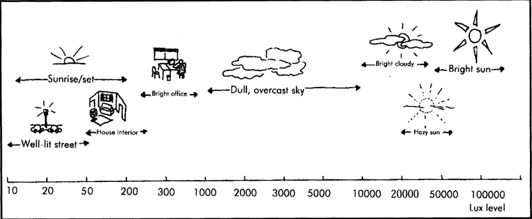
Whilst it may be true that a picture can be obtained in such low levels, it is equally true that the lower the level of light, the worse the quality of picture and the worse the colour saturation will be. It is also true that the contrast level will not be high enough to get anything but a very poor representation of the scene.
In practice, the higher the level of illumination there is within a scene (provided attention is paid to the contrast range) the better the resultant picture will be in terms of colour saturation and quality. The camera, however can only deal with a certain maximum level of illumination before it saturates and the pictures ‘burn out’, or become too bright resulting in whiter and less well defined pictures.
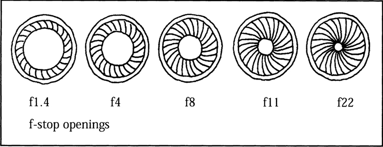
A way round this can be found by adjusting the aperture setting on the lens. The aperture control is the ring on the lens barrel marked in f-numbers (2.8, 4, 5.6, 8, etc.). The aperture is an adjustable hole through which the light passes. Each move to the next highest number halves the amount of light falling on the tube or CCD, each move to the next lowest number doubles the light passing through the lens (Figure 3.6).
Figure 3.6 Relationship of aperture to amount of light being passed
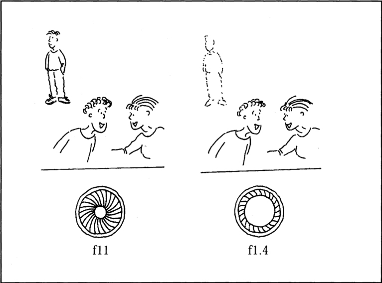
The aperture also has an effect on the depth of focus of the picture. Smaller numbers (f2.8, f4) will allow a smaller range (from front to back) of the scene to be in focus (Figure 3.7). Higher numbers (f11, f16) will allow a greater range to be in focus. The implications of this may give the lighting crew problems if the director requires a large depth of field in low light conditions or vice versa.
Figure 3.7 Effect of aperture on depth of field
If the light cannot be reduced to obtain a smaller depth of field (outside, in bright sunlight, for example), neutral density filters can be used. These are special filters, often fitted inside the camera and selected with the ND switch, which cut the overall light down by known amounts, requiring a smaller aperture number to be used to correct the light levels coming into the camera, hence reducing the depth of field.
How much light
The light source that we are all used to is the sun. It is very bright, a very long way away and by watching the shadows, and colour, we can judge the approximate time of day.
Exterior lighting tries to mimic the sun. This involves careful placing of the lights so that not only does the brightness appear right but, more importantly, all the shadows are going in the right direction and are the right length.
Interior lighting is more tricky because there may be elements of light appearing to come through a window, or an opening door, as well as light which is supposed to come from the interior lights the set represents.
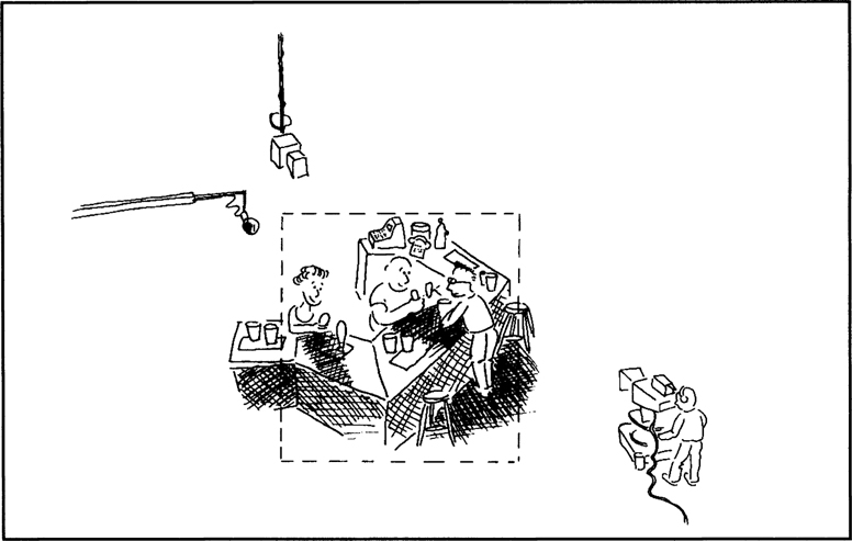
In either case we know that the camera cannot deal with the same range of contrast as our eyes. This leads the lighting person to a situation where an overall level of even lighting is required for the camera to function properly, and give good colour saturation, but still maintain the areas of brightness and shadow that our eyes perceive (Figure 3.8).
Figure 3.8 The darker areas in the scene will appear black to the camera. More light is needed in these areas so that the camera will see them

A further function of lighting must be considered when we realize that human eyes see things in three dimensions. This makes it easy to judge, for example, how far one person is from another, or how far away a background is. The camera will only see this in two dimensions, leaving lighting and control of depth of field (through aperture control) to fill in the third dimension.
One method of setting the correct light levels could be to flood the area with lots of light and then take up valuable camera time by trying to adjust it so that it looks right. This is not very scientific, or very satisfactory, and normally results in the scene looking as if it has been artificially lit (which it has).
The preferred method would be to work out how much light is needed, plot out where to put the lights and then measure the light to check the results. This will then lead to only minor adjustments being needed.
Preferred light level figures are available for cameras and it is possible to work out the approximate power requirements needed to achieve these levels. Meters are available to check the levels and colour temperature.
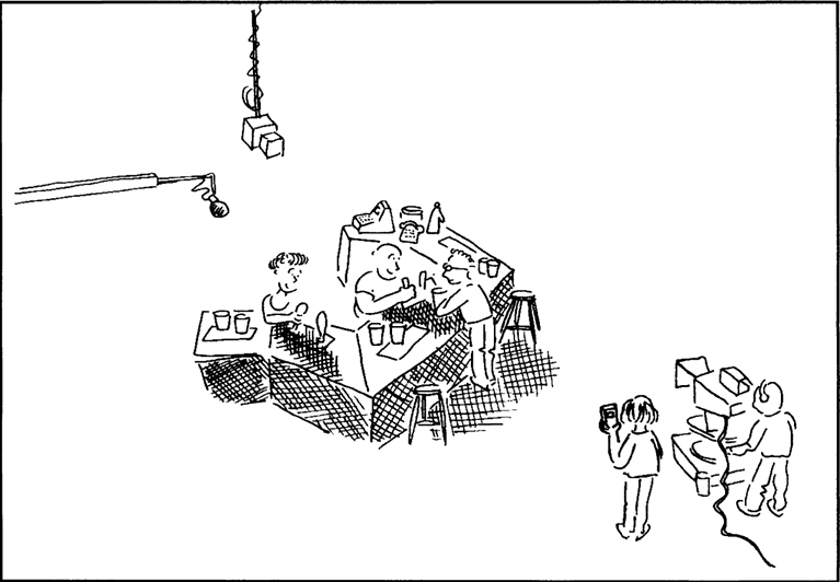
As a guide (Figure 3.9), a three chip CCD camera will have a typical requirement of 500 lumens per square metre and a three tube camera approximately twice this figure. This translates to a power requirement of about 250 watts per square metre for the three CCD camera and twice as much for the three tube camera.
Figure 3.9 If this acting area is 10m2 then a light level of approximately 500 lumens/m2 suitable for a CCD camera will need about 2,500 watts of lighting. Tube cameras will need at least twice this amount. Remember these are minimum levels
Decisions must be taken (as will be discussed later) relating to the use of one very powerful light (as with the sun) or lots of less powerful lights (as with complex interiors) to achieve these basic levels.
The standard light meter that is fitted to most still cameras, and some video cameras, measures the light reflected back from a scene (Figure 3.10). Although they are becoming more sophisticated, with types such as centre spot or zone weighted metering, they are of little help. They cannot measure the contrast range or the colour temperature. They rely on measuring the light reflected back from a subject and work out the resulting reading based on a standard 18% reflectance figure to produce an average brightness.
Figure 3.10 Reflected light readings are taken from the camera towards the scene. They are not sufficiently accurate for video
This works fairly well for black and white, but not all colours reflect the same amount of light giving false readings for a brightly coloured scene.
The preferred type of meter is a hand-held incident light meter. This is used by standing in the area to be measured and pointing the meter at the camera lens (Figure 3.11). The result is the amount of light actually falling on the scene. By walking across the whole area it is possible to judge where there is insufficient light and ascertain the overall contrast range.
Figure 3.11 Incident light readings measure the light actually falling on an area. It is now possible to decide which areas will be too dark for the camera to see into
A good incident light meter should give a digital readout of the actual light value in lux (lumens per square metre) and follow the laid down specification for spectral response which gives the correct weighting to colour balance.
A colour temperature meter works in a similar way inasmuch as it is used as an incident meter but measures the temperature of the light falling on the scene. Due regard should be paid to the problems of mixed lighting, where it would be more accurate to point the meter at the light source (in a window area, for example).
It must also be remembered that a colour temperature meter will not produce accurate measurements with discharge light sources which not only include fluorescent sodium or mercury street lights, but also the HMI and CSI family and carbon or xenon arcs. This is because ‘normal’ incandescent light consists of a continuous spectrum from red to blue, whereas these special sources have what is known as a ‘line’ spectrum’ fooling the meter into believing that it only consists of one colour.
When used as film or television lighting a mixture of different halides and gases are added to the discharge source to produce a ‘correlated colour temperature’ (Table 3.1). These figures can be obtained from the manufacturer and although quoted in Kelvin are only an approximation of the position the light would occupy on a Kelvin scale. These lights should be used with care because, as well as emitting ‘white’ light, they often emit large quantities of ultraviolet which can cause damage to the eyes and skin. Luminaire manufacturers are obliged to provide UV-absorbing safety glasses.
Table 3.1 Correlated colour temperature of discharge sources
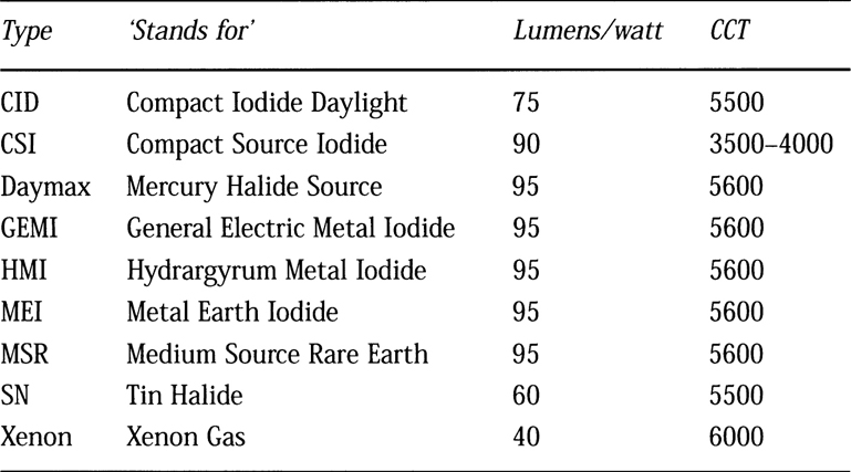
For comparison, normal tungsten lighting produces about 25 lumens/watt at 3200°K
Where there are differences in colour temperature it is possible to use colour correction filters to convert light sources to give an overall balance. Normally the predominant light source will be used to set the white balance on the camera and then the other sources balanced to that colour. It should be remembered that placing filters in front of lights will decrease the light output and compensations may need to be made. Reference to Table 3.2 will help in deciding which filter is required, it should also be remembered that lights become extremely hot in use, only the correct fireproof filters must be attached to lights and only then by using the correct filter holder.
Table 3.2 CC filters
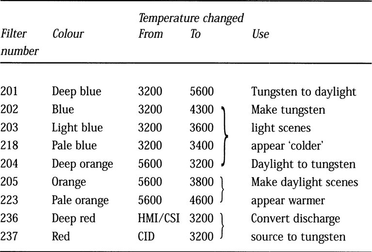
Standard light filter numbers have been used. Other manufacturers will have filters with different reference numbers.