
4 Types of luminaires
Whilst sources that produce light are often called ‘lights’, the preferred names are lanterns or luminaires.
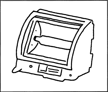
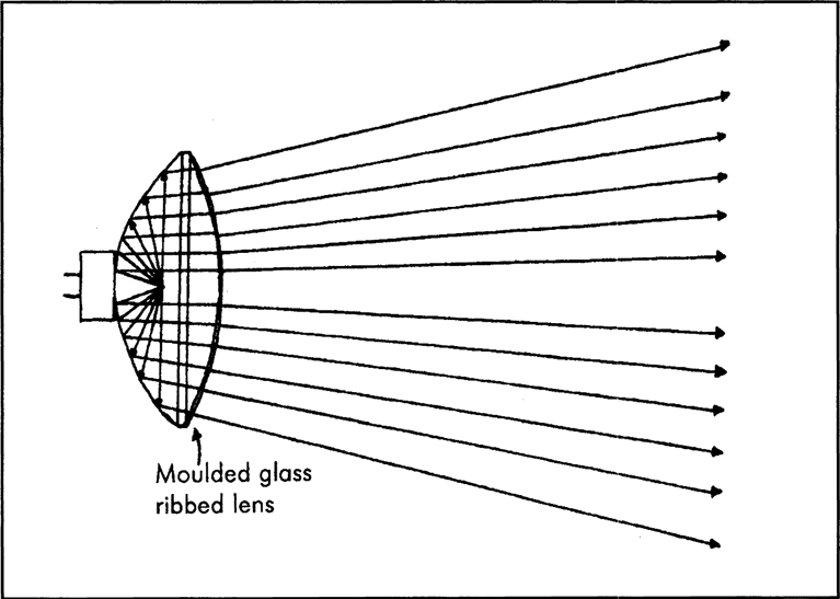
A luminaire will consist of (Figure 4.1) a metal case enclosing the light source, a reflector, to direct the light from the source forwards, and it may have a lens, to focus the light into a beam. There should always be some form of safety glass or wire mesh to prevent injury to performers should the light source explode. This metal casing will have some form of support, to allow the luminaire to be tilted or panned, fitted to a stand or hung from a light bar, and there will have to be adequate ventilation, so that the source does not overheat. This may take the form of forced cooling or rely on slots in the casing to allow air to flow around the lamp.
Figure 4.1 Parts of a typical lantern

Different combinations of shapes of cases, reflectors and lenses give a range of luminaires. Each type is designed for a specific purpose and is used in a particular way. It is not sufficient to describe a luminaire as a floodlight or a spotlight.
The term ‘floodlight’ is used to describe the width of the beam the luminaire produces (Figure 4.2). Typically this angle will be around 60°, but may be as high as 90° or as low as 40°.
Figure 4.2 Beam angles of typical flood and spot. Flood between 40°/90°, typical 60°. Spot between 20°/30°, special less than 10°
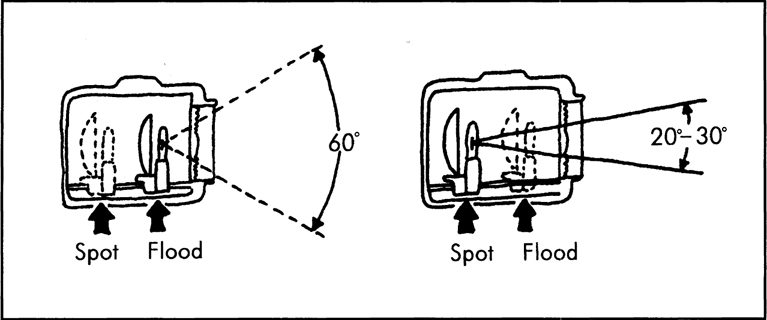
The term ‘spotlight’ also describes the width of the beam but is much narrower. Typical widths would be between 20° and 30°, but specialist lights are available with beam angles of less than 10°. Floodlights are normally placed closer to the area we need to light than spotlights. This is a practical example of the inverse square law we learnt about earlier. Floodlights will have a wider beam angle which will spread out more quickly than the narrower beam of a spotlight. This will mean that there is far less light intensity falling on the set as the distance between the luminaire and the object being lit increases. To maintain a reasonable balance of useable light with a normal power bulb the source to object distance has to be decreased. By reference to the same inverse square law, it is obvious that a spotlight, which has a narrower beam angle, will direct more light into a narrower space and can therefore be placed further away from the object being lit. Of course it would be possible to control the output of the spotlight using a dimmer. The problem with this method, if you remember back to the references to ‘colour temperature’, is that lowering the output will reduce the colour temperature, possibly needing a correction filter which in itself will reduce the output of the lamp! As you will see it is better to know a little about the physics of light than waste time experimenting with distance and levels and filters whilst the rest of the crew watch on in amusement.
Before we go any further it is worth considering the very basic function of a luminaire. The whole idea is to provide the right quantity and colour quality of illumination in order to make the scene look natural. This will involve making decisions about the type of luminaire that must be used to fulfil a particular purpose.
There will be a need to plan the positioning of the lantern. In studio this will almost inevitably mean mounting it at a height considerably above the acting area and the support systems that are used to do this will be looked at later. Location lighting has a different set of problems and will use different types of luminaires which will be covered separately.
Once the lantern is ‘out of reach’, we have the problem of how to adjust it’s direction and angle. It is possible to specify a luminaire with different methods of adjustment. The simplest is to have the housing in a cradle that can be adjusted in both vertical and horizontal planes by the operator climbing up to the lantern. At the same time any adjustment of the beam size or focus can be adjusted.
A simpler, and quicker, method is to specify a lantern that is ‘pole operated’. With this type of housing all the adjustments to the angles and the adjustments to the luminaire beam size, type and focus are carried out by inserting a special pole into adjusting slots fitted to the lantern. This is carried out from floor level, without the need for ladders, making it safer.
A more expensive method is available to the higher budget studio. All the adjustments of height, angle, beam size, focus and colour can be motorized and controlled by computer. This computer is often part of the lighting control board which will allow all the adjustments to be made and stored to a range of luminaires and called up as a scene. Remote control will often be available to allow the settings to be made from the studio floor and then downloaded into the main lighting control desk later. With this advancing technology a range of special luminaires have been developed that will allow the movement and colour of lights to be linked to music so that the whole lighting plot will alter with the changes in a song.
Within this ‘basics’ book we cannot cover every type of luminaire available from every manufacturer. All we will attempt to do is cover the principles of the basic types from the range of luminaires available to the lighting team.
Luminaires
The focusing reflector
Perhaps the most well known type of luminaire is the focusing reflector light. This is the principle on which the famous ‘redhead’ works. Because these units are quite small and light they are favoured by location crews (there is an ENG range especially for news interview situations). They have another advantage in that they produce surprisingly high outputs. The ‘focusing reflector name comes from the ability to focus the beam. The direct light output from the lamp will form one beam of light whilst the specially-shaped silver-coloured reflector produces another beam which is superimposed onto the direct beam. When the light source is close to the reflector (Figure 4.3) a narrow beam is produced (giving a spotlight effect), whilst moving the source further away from the reflector produces a wider beam angle (giving a floodlight effect) (Figure 4.4). The main problem with this open face type of luminaire is that it produces hard shadows, even on the so called ‘floodlight’ setting. There is also the need to provide a safety glass or wire mesh in case the source explodes. Not only must the safety glass be able to withstand the heat produced by the lamp, but it should also be strong enough to retain any flying particles of the lamp envelope should it explode. Proper circulation of air around the casing must be maintained.
Figure 4.3 Overlapping beam patterns of redhead set to spot

Figure 4.4 Overlapping beam patterns of redhead set to flood

Softlights
The true floodlight effect that we try to achieve can be seen by looking at the light from a cloudy sky. The cloud has converted the point source of the sun to a much larger source to produce an even, almost shadowless, light. If luminaires are to achieve this effect they must have very large reflectors. Their design means that the softer the light required the larger the luminaire must be.
Because of the need to produce an overall light level in order that the cameras can operate efficiently, we need a luminaire that produces not so much a ‘floodlight’ as a ‘softlight’. These softlights are used to set the overall lighting level and to fill in the shadows caused by normal spotlights or floodlights. This is why they are often referred to as ‘fill lights’. They are also ideal for producing an overall colour wash to a set without producing any noticeable shadows.
There are several designs that can be used to produce this diffuse and almost shadowless effect. The most obvious would be to mimic the sun behind cloud and bounce a hard source off a large white reflector, such as a sheet or an emulsioned white wall or ceiling (Figure 4.5). Essentially the source must direct light onto a diffuse matt white surface.
Figure 4.5 Bounced hard light. Light directed to sheet reflected back
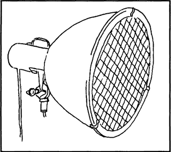
A typical softlight luminaire, shown in Figure 4.6, is shaped like a megaphone and has a white interior with a special frosted light source not unlike a domestic light bulb. Because of their shape, these luminaires are often called scoops.
Figure 4.6 Scoop
An alternative softlight uses a large box-like structure fitted with a number of strip lights (Figure 4.7a). These strip lights are often wired up as pairs, allowing for control over the total light output by switching some off. Typical values would be 2.5 kW and 5 kW using four 1,250 watt linear tungsten halogen lamps with each lamp fitted into its own primary reflector to achieve an even illumination from the secondary reflector. This has the advantage of allowing the lights to run at full power and prevents a shift in colour temperature caused by dimming circuits restricting the voltage the lights are designed to operate at.
Figure 4.7 (a) Large softlight. (b) Large softlight with louvered opening

Some softlights will have a collection of small sealed-beam lights fitted inside a large reflector. One design uses as many as ten, giving rise to it being referred to as a ‘10 lite’.
It is also possible to buy special fluorescent tubes (often known as ‘north lights’) which can be grouped into a large reflector to fill in shadow areas. These use low energy electricity power and run very cool. They are based on either six 36 watt or two 36 watt tubes (Figure 4.7b).
Because it is often desirable to ‘direct’ the softlight beam and control the spill of light from the sides, special spill rings, or louvered openings, are normally incorporated into the front of the luminaire. These are called eggcrates.
Because of the very large forward facing area of these soft light luminaires, they are not normally fitted with a safety glass. A glass this size would need to be very thick to withstand the heat which, apart from adding to the weight of the luminaire, would cut down the overall light output. For safety reasons a wire mesh is used to catch fragments of broken bulbs.
Cyc lights
Around the periphery of a studio is a backcloth or curtain called a cyclorama, more commonly shortened to ‘cyc’. This is sometimes black in which case no light should fall onto it so that the camera sees the background as black. More commonly, particularly for light entertainment programmes, it will be coloured and needs to be lit.
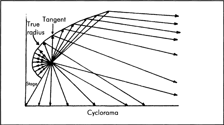
Knowledge of the inverse square law will help to understand that the part of the backcloth nearest the light output (normally the top) will have a considerably higher lux level than that at the bottom which is further away from the source.
This calls for special types of luminaires, called cyc lights, to provide an even illumination from top to bottom. Figure 4.8 shows the special reflector shape used and it can be seen that the bottom of the cyc is only receiving direct light whereas further up the cyc there is more reflected light. This is a crude attempt at cheating the inverse square law and is relatively successful. For a true constant lux up the whole cyc it is necessary to use lighting from the top and the bottom.
Figure 4.8 Shape of cyc reflector, with ray diagram
Using these special reflector shapes and a large number of cyc lights it is possible to produce an even lighting effect where, at least, the distribution of light falls off evenly and leaves no noticeable light or dark bands.
The positioning and spacing of these luminaires is crucial if an even lighting effect is required. A typical manufacturer’s recommendation is to start with the luminaires 1.5 metres from the cyc and keep the centre spacing between luminaires at 1.5 metres.
These special cyc luminaires will normally use a linear tungsten halogen bulb (Figure 4.9). This provides a large light source which will help to produce a more diffuse and even lighting direct from the filament.
Figure 4.9 Linear tungsten bulb in single cyc lamp
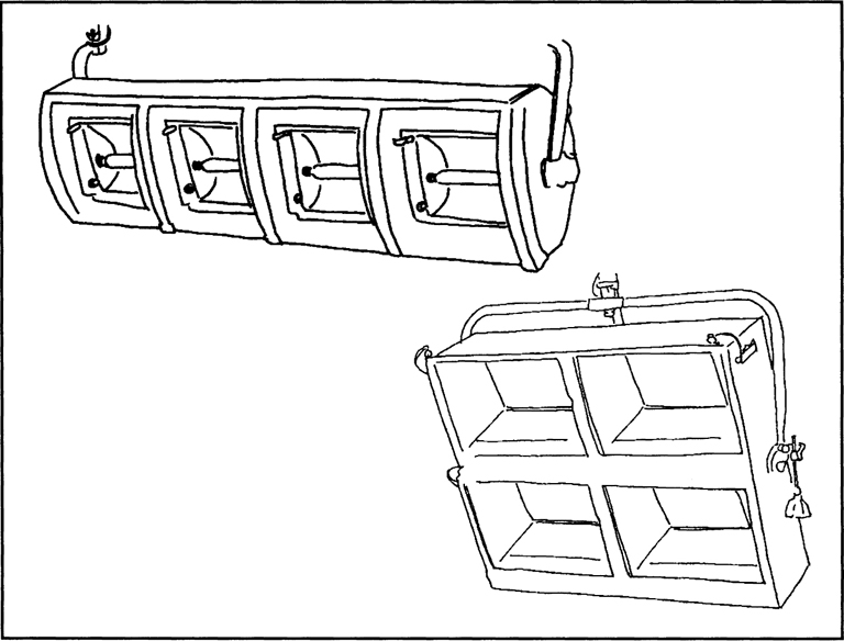
Although these luminaires are available singly they are normally seen in sets of four (Figure 4.10), all in one casing. This allows for colour mixing with a red, blue and green colour filter fitted to each of three and the fourth left white. This gives great flexibility if a colour wash background is required. Adding a little white light to a primary colour will desaturate the colour and help to keep the lighting more subtle and even.
Figure 4.10 Two types of 4 block cyc lights
Although these cyc lights are normally suspended from the grid to light the backcloth from the top, it is possible to use ground row lights (often called ‘footlights’, in the theatre industry) to light the backcloth or base of the set from floor level.
Some manufacturers supply a linear row of four that have special hinges to allow the whole row to be bent around the edges of the cyc, providing even illumination in the corners.
Because the position of the cyc luminaires is critical to the light distribution and it is essential that the total amount of light falling onto the cyc can be controlled, they will always be connected to dimmer circuits. It does not take a mathematical genius to realize that a very large number of dimmer circuits can be eaten up by these luminaires alone!
From a safety point of view the casings must be fitted with suitable safety glass or mesh to prevent shattered bulbs falling on the performers.
Beam lights
As we have seen the construction of luminaires is not just a question of putting a light source into a casing and pointing it in the direction we want the light to go. The science of physics is employed to produce a reflector shape which, in conjunction with a size of light source, will produce the beam shape we require for a particular purpose. It is the type and size of reflector, and its coating, together with the bulb size that will determine whether a beam is ‘flood’ or ‘spot’, hard edged or soft edged.
One of these special reflector designs uses the shape of a parabola. A parabolic reflector (Figure 4.11) is designed, as its name implies, to produce a parallel beam of light. Luminaires using this principle are known as beam lights.
Figure 4.11 Parabolic reflector with ray figure giving near parallel beam
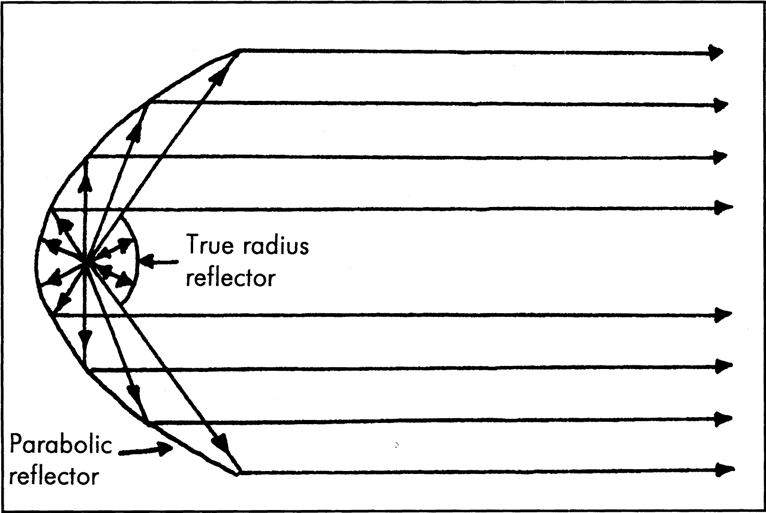
If it were possible to produce a true point source of light and place it at the focal point of this parabolic reflector, a parallel beam of light would result which would be the same diameter as the reflector. In practice this is not an achievable possibility, but we can get quite close.
The closest we can come to a point source is to reduce the size of the source as much as possible, this calls for the use of a very small bulb. The laws of electricity dictate that this small bulb will be most efficient if it is run from a low voltage and using a high current to produce the desired wattage. The transformer needed to convert higher (mains) voltages to these smaller voltages is normally an integral part of the light’s housing.
In order to direct all the light onto the parabolic reflector, a true radius reflector is placed in front of the bulb. This prevents any direct light escaping and directs the beam into the parabolic reflector. This reflector may be a separate fitting or may be an integral part of the envelope of the lamp.
Because the light source, although small, is not a point source a beam width of about 5° to 7° is the result. With some beam lights it is possible to move the light source slightly backwards or forwards around the focal point which will give some degree of control over the width of the beam. In practice this amounts to a variation of only about 2° or 3°.
To try to keep the beam as near parallel as possible and prevent any light spilling from around the beam, spill rings are fitted inside the casing which make these luminaires very easily identifiable (Figure 4.12).
Figure 4.12 Typical beam light construction
These luminaires produce high light levels in a narrow, slightly soft edged, beam at great distances from the source. A typical 500 watt model will produce around 3,000 lux at a distance of 15 metres. This makes these specialist luminaires most suitable in large venues or as a compact follow spot in smaller video light entertainment programmes.
Consideration has to be given to safety by fitting either a safety glass, or fine wire mesh, to prevent pieces of damaged bulb falling out of the front of the lamp.
Sealed-beam types
So far all the luminaires we have looked at have relied on only two things. An ordinary tungsten halogen bulb, fitted into a casing, and a specially designed and coated reflector have been used to produce a particular shape of beam. No mention has been made of any type of lens placed either in front or behind the light source.
A close relation to the beam light is the sealed-beam unit. This is most commonly seen as a car headlight, but it has uses in film and video work.
The sealed-beam unit (Figure 4.13) has the same small light source and a parabolic reflector but instead of having a reflector in front of the source, to direct the light output back onto the rear parabolic reflector, it has a lens welded onto the front.
Figure 4.13 Sealed beam unit construction
The lens, reflector and size of the unit normally produces an oval shaped beam. The most common sealed-beam units are from the PAR range, usually PAR 38 and PAR 64. The number comes from an old manufacturer’s code which denotes the number being the diameter of the unit in the old imperial measure of eighths of an inch. Taking a PAR 64 as an example, 64 eighths of an inch is 8 inches making the diameter of a PAR 64 8 inches (approximately 205 millimetres).
Sealed-beam units come in a range of wattages and give very high light outputs. There is no need for them to be fitted into special casings but many manufacturers do produce a simple, cheap, housing allowing them to be fitted to a normal lighting grid (Figure 4.14). They are used by many small studios as sound-to-light units for pop videos.
Figure 4.14 Typical housing (Parcan or Punchlite)

Because the only way of controlling the beam width is by an integral, sealed, lens, manufacturers produce a range of units offering a variety of beam angles from ‘flood’ to ‘spot’. Typically the oval beam could be from 12° by 6° up to around 25° by 60°.
To avoid complicated fittings on a simple housing, manufacturers not only produce these sealed beam units in a range of diameters and beam angles but also offer different coloured lenses as well as white.
Using a parabolic reflector effectively needs a point source of light. This means making the bulb as small as possible and we know, from looking at beam lights, that small low voltage bulbs work best. In practice the video sealed-beam units are normally supplied to work from either 250 volts or 120 volts. The 120 volt variety, apart from needing the correct voltage, offer a greater range of beam angles and higher efficiency.
With the bulb sealed inside the unit, there is not much chance of a blown filament causing any damage. However, it has been known for whole units to explode and because of this some manufacturers have a wire mesh at the front of the luminaire for protection. There is a legal requirement for the PAR 64 to be fitted with safety mesh.
The fresnel
The fresnel range of lights is the workhorse of a studio or location lighting rig. They each have a reflector, a bulb and a special lens (Figure 4.15).
Figure 4.15 Typical fresnel

We introduced the idea of a lens in front of the bulb with the sealed beam type earlier. This luminaire gets its name, ‘fresnel’, from the inventor of the special type of lens it uses. The ‘s’ in fresnel is silent, so the correct pronunciation is ‘frenel’.
If a normal convex lens was used it would have to be very large, making it very heavy, and liable to crack easily with the heat of the light. Fresnel discovered that if he cut an ordinary condenser lens into concentric rings, each of which formed part of the curved lens surface, and then stuck them together the resulting ‘flat’ lens would produce the same effect (Figure 4.16). Being lighter and thinner there is no problem with heat build up being dispersed through its larger surface area.
Figure 4.16 Exploded fresnel construction

The fresnel luminaire has a part spherical reflector with the bulb placed at the centre of its radius. The resulting spread of light is condensed into a beam as it passes through the lens.
The control over the width of the beam is dependent on the position of the bulb and reflector relative to the lens. If the bulb and reflector are moved as one unit closer to the lens a wider beam angle (flood) is produced. With the reflector and bulb assembly further back from the lens a narrow (spot) beam is produced (Figure 4.17). Typically variable beam angles of between 10° and 60° are offered by manufacturers.
Figure 4.17 Beam angles

The fresnel is an ideal luminaire to produce the light source for the performer’s soft-edged key light or back light. It is also often used to provide illumination for larger areas of a set. The perfect fresnel spotlight will have an even light intensity across the whole of its beam width, at whatever angle is being used.
The PC
Very similar to the fresnel is the PC, or plano convex, luminaire. This uses a conventional lens instead of the fresnel, but is otherwise identical in construction and performance.
Some lighting supervisors prefer the PC to the fresnel because its prime advantage is that it produces much less spill light than the fresnel and it has a better defined soft edge to the beam. The disadvantage is that some designs will have noticeable hot spots, or even darker pools of light in the middle of the beam. It is possible to minimize, but not eliminate, this effect by placing special light diffusers at the back of the lens.
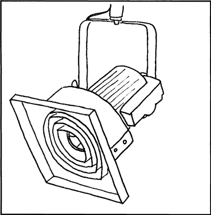
Profile spotlights
‘Profile spots’ are not universally the same thing. The actual name will depend upon which country you work in, which lighting catalogue you look in, or how precise a description of the luminaire is used. In the USA this range tends to be called ‘ellipsoidal luminaires’, theatres may call them ‘follow spots’ or ‘effects projectors’. This confusion over names is brought about by the range of uses for this particular luminaire.
The confusion derives from the complexity of the lantern (Figure 4.18). An ellipsoidal reflector is used with a light source placed at its focal point. In front of this is either a plano convex (PC) or, to reduce weight, a fresnel lens. This lens produces a beam of light that passes through a variable aperture gate, beyond which is another lens that is used to focus the beam. The result is a narrow, sharply focused, beam of light.
Figure 4.18 Profile

By altering the distance between the two lenses both the beam size and the focus are altered. The variable aperture gate consists of four shutter blades acting on the beam independently. This allows the beam to be shaped.
When used as a follow spot, the aperture is normally an iris, similar to that found on cameras, which can be controlled from fully open to fully shut with one lever.
Because whatever is placed in the gate can be focused, the beam can be shaped into any desired pattern. A range of commercially produced metal cut-out shapes, called gobos, are available to make the beam star shaped, keyhole shaped, triangular, etc. It is possible to buy blank gobos and make your own shapes.
It is also possible to get effects wheels that use a small motor to rotate a slide to produce effects such as fire, clouds or rain.
The main disadvantage with these luminaires is their size and weight. If a particularly narrow beam is required over a long distance it will involve a housing over a metre long. This can lead to instability of the luminaire on its mounting causing the effect to vibrate visibly, ruining the effect.
On location
There are several reasons why luminaires designed for studio use cannot normally be used on location. ‘On location’ tends to mean that we are operating outside the studio in confined spaces or in the open air. This will always mean that the equipment has to be transported to the location, rigged, used, taken down and transported away. As time is money, it makes sense to have a specially designed range of luminaires that are light, easily transported and erected.
It is possible, with major film or video productions, to hire a specially built vehicle with its own generator and lighting rig. This use of a ‘lighting truck’ will normally include a specialist lighting crew who are experts with all types of exterior shooting and have the luminaires, accessories and supports to provide exactly what the director requires. It is beyond the scope of this book to say any more than that this facility will provide what is effectively specialist ‘studio’ lighting using everything from huge power ‘sun spots’ through to the whole range of luminaires and lighting control circuits found in the largest theatres or studios. This sort of location work will almost always involve an ‘outside broadcast’ truck which effectively turns our location shoot into a multi-camera studio shoot.
For the purposes of this ‘basic’ text we will assume that location video is the normal small-scale single-camera shoot, often shortened to PSC (portable single camera) or ENG (electronic news gathering), involving a small crew of three or four. This type of shoot will use either outside locations (e.g. street interviews or the park) or inside locations (e.g. the office interview or some action taking place inside a real building), but all will have the requirement for something small and portable in the way of lighting.
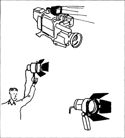
There are three basic types of location lights, camera-mounted, hand-held or stand-mounted (Figure 4.19). All these luminaires are normally referred to as ‘portable luminaires’ to distinguish them from the more powerful ‘location luminaires’ which are similar to studio luminaires, normally used with dimming and control circuits, but specially designed to withstand constantly being moved about and used in the elements. These location luminaires are more often than not supplied as daylight colour balanced.
Figure 4.19 On camera and hand held lights
There are only two ways of powering these lights, either from batteries or from the available power.
If the lights are battery operated the power may come from the camera or from a separate battery, but will always involve balancing how much power the battery can supply for the time required, against how much light is required.
The camera-mounted variety tend to be low powered, not normally exceeding 300 watts, and consist of a small, efficient quartz bulb which is often contained within its own reflector and lens system. These bulbs are over twice as expensive as the normal quartz halogen bulb and do not last any longer (50 hours is an average bulb life), but have the advantage of a built in reflector system which makes them considerably more efficient than the alternative separate bulb and reflector types. Manufacturers often quote ‘the output is equivalent to a normal bulb of twice the wattage’. You should remember both basic electricity and physics principles when you consider this. Twice the watts does not mean twice the light output but if you could use less power for a required light output then the battery will last longer, giving you more available time between charges. These lights are designed to illuminate a subject at distances of 2–5 metres. Illumination figures for a typical 100 watt unit at 2.5 metres would be 700 lux and for a 200 watt version at 7 metres you could expect 1250 lux. Some luminaires will be offered with a variable beam width ranging from 20–60 degrees but remember the inverse square law relating to how much light you will get if the beam is spread out.
The selection of the light will be the lighting team’s decision, but its operation is obviously the camera person’s responsibility because it is mounted on the camera. There are two mounting options. One is to clip it onto the ‘hot shoe’ provided on most camcorders, the other it to fit it to a bracket which is screwed into the camera tripod fitting at the base of the camera.
These small camera mounted lights require a degree of sense from the camera operator. The lit area will be very small, often just covering head and shoulders, and will move with the camera. The camera should be zoomed in to cover the area and not moved. These clip on lights are definitely for the ‘reporter’ situation, you cannot expect to illuminate large areas with one small light source that moves with the camera. A range of accessories is normally available including barn doors and diffuser filters.
Because the bulbs fitted are halogen they will have a colour temperature of 3200°K, this provides an interesting set of decisions. If the light is used in darkness purely to illuminate a reporter then the camera white balance can be set to tungsten. If used as a fill in light during daytime you will need to filter the light, to correct it to daylight, and set the white balance to daylight. Going back to what you learnt about colour temperature, you may opt for a ‘mixed lighting’ situation. A low powered (say 20 watt) unit left unfiltered will make a reporter’s face appear slightly ‘warmer’ in daylight, which may give a more pleasing picture.
The hand-held types are always run from a separate battery either fitted inside the lamp housing or, for larger power options, may be worn by the operator. They are available in a range of power ratings up to 500 watts and are often offered with crude focusing devices that allow them to be run as spot or flood. Many have alternative power settings, using two bulbs in the same housing, to give outputs from either one or both bulbs.
Apart from needing another crew member, to hold the light, a major advantage of these units is that they are separate from the camera and height, angle and position are all controllable, giving greater flexibility over a range of shots. Remember, though, that there is a limit to what can be done with one light. Again they will need to be matched to the prevailing colour temperature.
The stand-mounted units are more like the smaller studio lights. They are designed to be used on mains power and are normally used in a two- or three-light arrangement. The three most commonly used types are 650 watt, 800 watt or 1 kilowatt focusing reflector luminaires (see description earlier). These are both designed to work at lamp to subject distances of between 3 metres and 6 metres and will provide useful lux levels of between 3000 lux and 900 lux. Although called focusing reflector types they should be thought of more as having a variable beam width from about 40–80 degrees. It is not possible to make them spots or floods in the true sense of the word.
Also common in this range is a 500 watt open-faced fill light and a 2 kilowatt focusing reflector. This larger focusing reflector is designed to be used more as an interior ‘studio light’ to illuminate larger areas from a distance of about 10 metres.
This range of portable luminaires is often kept in their own carrying cases as ‘location kits’. Stored in the cases with the luminaires will be things like a range of scrims, barn doors, accessory holders, fold-up reflector screens and portable stands.
Special, smaller and lighter versions are available for ENG use and the kits will often comprise of luminaires for fill, key and back light as well as all their accessories and small stands.
Before using any of these mains powered lights it is imperative that you remember the rules of electricity. If we take a simple example of four 1 kilowatt lamps, they will consume 18 amps at 220 volts. If you are working indoors with normal power sockets then it stands to reason that there are two problems, any extension cables must be capable of taking this power, and a standard four-way domestic extension block and cable is definitely not capable, and there must be sufficient power available, a ‘standard’ 13 amp socket is not capable of supplying this amount of power. You will need to think this out carefully, it may be that you have to plug the lights into different rooms and use long extension cables. The way most domestic installations are carried out is to make 30 amps available through four or five sockets in the same area. Before you risk the embarrassment of blowing a fuse and not knowing where the fuse box is located, or, worse still, causing a fire in someone else’s property you must check where the fuses are and what power rating is available to you. It is very unwise to assume that all the 13 amp sockets on the same floor level are able to supply 13 amps each.