
7 Dimmers and control
The studio is a completely controllable environment. A powerful tool most studios provide is the facility to smoothly change the brightness of light, and the number of lanterns in use. This opens a wealth of possibilities for the lighting designer from the subtle, almost imperceptible, fine tuning of a lantern lighting a presenter’s face turning to interview another guest, to the full scale excitement of a cabaret performance with flashing floor lights, multi-coloured backgrounds, follow spots and special smoke effects. All can be done through the lighting control system.
The principle is simple. When we plug an ordinary lantern into the mains its bulb will give the maximum output of light. Plug it, instead, into a dimmer unit and the dimmer, by changing the power fed to the lantern, can smoothly change its output brightness from fully off to fully on. To tell the dimmer unit what output power is wanted a low level control signal is fed to it from the control desk, which could be some distance away.
Each lantern is plugged into its own numbered dimmer. Often the lantern will have a large label on its support to help identify it. The numbers correspond to controls on the desk. The lighting operator, by moving fader 15, for instance, can make lantern 15 brighter or darker.
It is in the flexibility of the desk that the creativity lies. The simplest of desks may have only six faders, each controlling only one lighting channel. More complex ones will have more channels, duplicated faders (allowing lighting scenes to be preset) and switches for instant black out of individual channels or the whole output.
The most elaborate desks will have the ability to control many channels (often hundreds), to memorize lighting levels and changes, to automatically initiate fades, to allow a sound signal (e.g. music) to control lighting levels, and even control the movement and colour changes of a particular lantern. With computer technology there is enormous scope for the lighting designer who can now plan the most complex lighting effects and save all of them onto a floppy disc to be recalled by the control desk at any time in the future.
With any lighting set up there will always be a need to control the individual intensity of each luminaire. Controlling the intensity allows the proper balancing of light in order to achieve the desired visual effect.
In television, unlike theatre, this effect can only be judged correctly when looked at on a monitor showing the camera’s view of our lighting attempt. The camera and our eyes differ in their perception of contrast ratio and colour.
Location lighting will almost inevitably have to resort to altering the light-to-source distance, using scrims or using ND filters. Studio lighting, however, will have more luminaires available, a more complex rig and a fixed installation. Part of the studio lighting arrangement will include dimmer circuits and a lighting control board. The job does not become any easier, it is just done a different way.
The basic interconnection between a luminaire and its dimmer and the control desk is shown in Figure 7.1. The layout is a simple one in principle. The luminaire is connected to a socket on the lighting grid, this socket ends up as a plug that will plug into a lighting patch box, the socket on the lighting patch box goes to the dimmer which supplies varying amounts of electricity. How much electricity is available to the light, via the dimmer, is controlled by the fader circuits contained within the lighting control board.
Figure 7.1 The luminaire is wired from the grid to the lighting console via the patch bay and the dimmer circuit
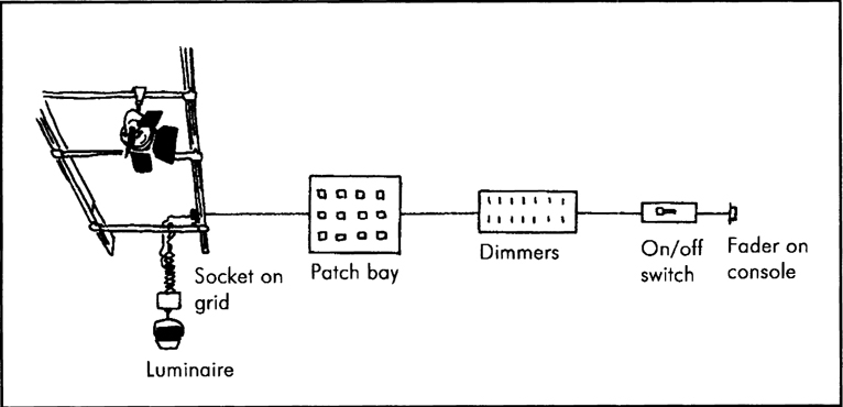
It would be possible to connect the luminaire direct to a dimmer with a fader, but this reduces the options available if something goes wrong, like a dimmer failure. With this standard interconnection system involving sockets on the grid terminating in a patch box we have flexibility.
A combined dimmer and control pack, that will control up to four small redheads, is available for location work. This can be mounted to a special support system, giving local control over the light intensity.
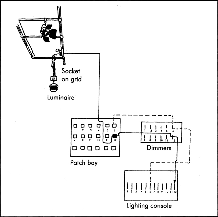
With a large number of luminaires, sockets on the grid and dimmers it helps to have a simple system to identify which dimmer controls which luminaire. The normal arrangement is to have a unique number attached to the luminaire. The sockets on the grid are numbered, determined by where they are on which grid member. The plugs from these sockets are numbered on the patch box. Each socket on the patch box is marked with the dimmer number. This is shown in Figure 7.2(b), and you can see that light 12 is connected through C4 to dimmer 12.
Figure 7.2(a) Interconnection luminaire to desk
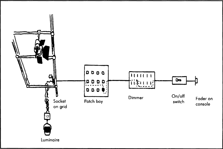
Figure 7.2(b) The dotted line shows that C4 could be plugged into 6 on the patch bay and light 12 would then be controlled by dimmer and fader 6
We learnt earlier how to work out the current taken by a luminaire of a known wattage. It is essential that this knowledge is put into practice when fitting plugs, sockets, cables and dimmers together. A typical 2 kW light will take nearly 10 amps. Plugs, sockets and cables should be able to take at least that amount to prevent overheating and possible fire damage.
Often a 100% margin is allowed for cable, in this example a cable with a 20 amp rating might be used. If the luminaire was a 5 kW model it would need about 23 amps and clearly could not be plugged into the same socket or use the same cable. Dimmers are normally supplied as 5 kW or 10 kW versions, if more than one luminaire is connected to the same dimmer (typical in the case of cyc lights), a little mathematics will prevent the dimmers being put at risk.
Dimmers
A dimmer is a device that controls the voltage fed to a luminaire. If the voltage is reduced the light source will not glow as brightly. If it does not glow as brightly it will not be at the original colour temperature. If a scene is to be shot in very low-level lighting it may well be necessary to re-do the camera white balance to prevent the camera portraying the scene as red.
Until the mid 1960s dimmers were manually operated variable resistors, which altered the voltage available to the luminaire by sharing the available voltage between themselves and the light source. Today the majority of dimmers use a device known as a silicon controlled rectifier (SCR). These are also called thyristors or triacs. Thyristor controlled circuits are preferred, but are more expensive, because they are more stable in operation.
Within the scope of this book it is only possible to give you a rough idea of how these circuits work and to look at the problems associated with them. Basically, if a very small voltage is applied to an SCR it will ‘switch on’ and allow voltage to be supplied to the lamp. This very small voltage is supplied by the lighting control desk via a small fader. Depending on the value of the voltage, control circuits will switch the thyristor on and off for very short periods of time. This produces a ‘chopped’ waveform (Figure 7.3) and herein lies the problem with dimmer circuits.
Figure 7.3 Chopped thyristor output

Large electromagnetic patterns are set up around the dimmers and through the associated cabling. This can lead to interference with the audio circuits, and can cause lamp filaments to vibrate and ‘sing’. Controlling these problems is expensive, involving special circuits to be fitted to the dimmer controls circuits and special cables to be used for microphones.
In January 1992, an EC directive was issued laying down regulations to control electromagnetic interference from all devices and increasingly manufacturers are paying more attention to this problem.
Dimmer systems normally work on a principle known as ‘square law dimming’, this means that the square of the number on the fader (marked from 0 to 10) relates to the power output of the lamp (Table 7.1), e.g. 7 on the fader represents a light at 49%, 4 on the fader represents 16%.
Table 7.1 Square law dimming
The square fader setting gives the percentage light output e.g. Fader at ‘6’ equals light output of 36%
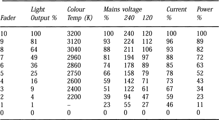
The table shows the values for the operating parameters of tungsten halogen lamps when used with a square law dimming system. It should be noted that the ideal colour temperature figure is seldom reached in practice and most lamps will run about 100–200 °K less throughout their range.
Table reproduced courtesy of Strand Lighting
Lighting consoles
Since SCR dimmers became available, requiring only a small (0 to 10 volt) control voltage to make them work, it has been possible for manufacturers to make compact, but very versatile, lighting consoles allowing a range of possible control over the luminaires.
The simplest consoles consist of one fader per dimmer, only allowing each light to be faded up and down independently, the most complex are computer controlled allowing whole ‘scenes’ of lighting changes to be automatically triggered and stored on disc and simply loaded into the console whenever they are needed.
Manual systems have the disadvantage of needing a fader for each channel. This could mean a desk having 50 or 60 individual faders, making it quite large. Every time a light needs to be adjusted, a fader will need to be moved. Some desks will have two or more groups allowing individual lights to be set to different levels controlled by one master (group) fader. Some lighting operators still prefer this system because of the simplicity of fading up (say) channel 9 and knowing that luminaire 9 will fade up.
Memory system lighting consoles are really small computers. Instead of having one fader for one dimmer, they have one fader (which is often a wheel). Like computers there is a keyboard which allows this fader to be assigned to a dimmer. Instead of using the fader to determine the level of a light it is often possible to use the keys to enter a percentage brightness which can speed things up. Any number of dimmer settings can be entered into the memory as a cue, and recalled by calling up the memory number.
Figure 7.4 Simple one fader per channel desk

Figure 7.5 Memory desk
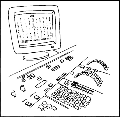
The memory is normally protected by internal batteries so that if the power fails, or the console is switched off and moved, the cues are still stored and can be recalled. Larger systems will be fully computer controlled and can store complex fade in and out information, sound-to-light instructions, cross mixes and can couple cues together.
This is helpful if a studio is used for many regular recordings using the same lighting pattern. All you need to do is set the lights once, commit it to memory, store it on disc and recall it next time it is needed. Of course the luminaires will have to be set in the right positions on the grid each time, but the levels and mixes are instantly recalled.
Because the lighting console only sends a small control voltage to the dimmers it is possible to use the console anywhere in the studio, via an extension cable. This means that the lighting director could set and adjust the lights from the studio floor before taking the console back to the lighting control area for the recording. An extension of this idea is to use a remote control handset in much the same way as a video tape recorder can be ‘programmed’ from a distance.
With the modern, sophisticated, control systems and digital technology it is possible to control the movement of the luminaires, as well as their brightness, from the computer. This has lead to a range of luminaires being developed that are particularly suited to pop music programmes, combining different light levels and colours with swinging movement, all operated by the computer.
We have come a long way from using different lengths of wood to try to fade up several manual dimmers at one time!