
Operation and controls
Glen L. Bostick, Manager of Systems Engineering (Instrumentation & Controls, Research & Development, Innovation & Patents), Fenton, MO, United States
Abstract
This chapter seeks to provide the reader with a basic understanding of the factors influencing the operation and control of a heat recovery steam generator (HRSG). While intrinsically a passive device with the HRSG responding to a multitude of plant influences impacting steam production and temperature, there are several fundamental controls associated with a natural circulation HRSG that are common and, for the most part, independent of the original equipment manufacturer. In addition, several authorities, such as ASME and the NFPA, have defined required schemas to ensure a minimum level of inherent safety for the operation of the equipment. These control approaches are presented in a very simple and easy-to-follow outline.
Keywords
HRSG operation; startup; process influences; level control; temperature control; condensate detection
14.1 Introduction
When starting to write a chapter on operational controls for a major piece of industrial equipment serving a critical role in an essential national/world market, one ponders the complexities and intricacies that they will dive into and accurately expand upon while trying to work within a reasonably allotted space. This chapter is after all only a part of a greater work directed at the presentation of a concise and informative treatise on heat recovery steam generators (HRSGs).
The design and application of HRSGs is nearly infinite. The controls and operation of each plant can vary greatly based upon equipment, location, user preference, and of course process design. The controls engineer must take all of these facets into consideration to create a suitable and unique operational plan for each system. The generation of an all-encompassing operational guideline would be very challenging and fated to be incomplete owing to the vast permutations that can be encountered. For clarity of scope, this chapter is limited to a general presentation on operation and controls associated with the HRSG proper operating behind a combustion turbine (CT), a very typical application. To be sure, the effects of other plant systems on the HRSG will be addressed in the applicable discussions, as appropriate, to demonstrate the full range of necessary controls. However, it is not the intent of this work to address balance of plant (BoP) equipment or HRSG auxiliary equipment (e.g. burners, selective catalytic reductions) in detail. The reader is directed to other readily available resources for a more complete rendering on those components.
14.2 Operation
It is ironic that one charged with the development of a chapter on process controls and operation must begin by acknowledging, with some chagrin, that at the core of an HRSG lies a very passive device. In fact, the thermal designer’s job, while not part of a job description, is effectively to minimize the needs for active controllers. Proper design and location of heat transfer surfaces allow the HRSG process parameters (steam temperature and pressure) to submissively follow the heat source’s lead while staying within acceptable operational ranges.
While the HRSG will “follow” the energy being input, the manner in which the HRSG responds to these transient conditions is critical for ensuring operational suitability. Therein lies the opportunity for controls engineers to apply their trade. Large deviations away from desired set-point conditions can lead to inefficient operation (i.e., elevated heat rates) and premature failure of components (internal and external to HRSG). Control trips and interlocks will generally serve to provide mechanical protection but excessive process upsets may still result in operational runbacks costing the plant in lost production. If severe enough, process upsets will result in the entire plant “tripping,” which is the immediate halt to all operation. Tripping a power plant or process plant is very costly in terms of lost production and imposed “loss of life” to components subject to the stresses that result from large pressure/temperature gradients caused by an on/off step change in the system. Even part load trips (i.e., the CT is not at full rated output) result in a disproportionate consumption of the system life when compared to normal operation.
14.2.1 Plant influences
As noted, the HRSG surface dutifully absorbs energy provided by the upstream energy source (e.g., CT, coke oven, gas/oil fired fresh air system, etc.). Consequentially, any influence on the energy delivered to the inlet of the HRSG will impact the boiler’s performance. Table 14.1 provides a brief list of the largest influencing factors and the consequential effect on a single-pressure (1-P) HRSG. While steam temperature is typically controlled, Table 14.1 indicates the impact on steam temperature while allowing the HRSG output to solely follow the heat input.
Table 14.1
Influencing factors on 1-P HRSG steam output

14.2.1.1 Ambient temperature
Specific to an HRSG located on the tail end of a CT, the ambient temperature influence results from the design fundamentals of the turbomachinery in that a CT produces a nearly constant volume flow rate with mass flow output following ambient conditions. A hotter day has less mass flow (i.e., less dense air) yet hotter gas while a cold day has more mass flow (i.e., more dense air) with cooler exhaust. As the designer has fixed the surface of the superheaters (SHTR), evaporators (EVAP), and economizers (ECO) around a “design” point, the surface will respond according to variations from this point. On a hot day, the SHTRs are essentially “over designed” owing to the elevated exhaust gas temperature entering the heat transfer surface and the reduced steam flow being produced by the EVAP system. As the evaporator system sets the demand for water, on a hot day with less steam being produced, the flow of water through the economizers is reduced and the economizers may also over perform.
As many HRSGs contain multiple pressure systems, the net effects of ambient conditions will vary across pressure levels as will the operational control of the other systems (i.e., high-pressure (HP) system performance will impact intermediate-pressure and low-pressure performance). For example, the influence of a reheater (RHTR) bypass on the high-pressure system steam production is almost one to one, meaning that an increase in flow through the RHTR bypass for RHTR temperature control will result in an increase in HP steam production, which in turn further reduces the RHTR steam temperature owing to the increased steam flow passing through the same RHTR surface.
14.2.1.2 Combustion turbine load
CT load makes reference to the relative output of the turbine when compared to the defined rated output at the present ambient conditions when operating at the design firing limits of the CT. Thus CT “base load,” or rated CT power output at ambient, is not a fixed single value but can vary significantly with changing ambient conditions.
As base load operation reflects the optimum efficiency point for the CT, it is desirable for the plant to function in this mode. However, HRSG plants often require large amounts of flexibility in operation to accommodate process needs or power output requirements and CTs/HRSGs in modern designs are often required to operate at “part load” (i.e., a CT power output less than base load). While each family of CTs is different, part load operation typically results in a throttling of intake air and burner staging so to address flame stability and emission requirements. The consequence on the energy input to the HRSG is similar to that of a hot day (i.e., less mass flow at a higher temperature) as depicted in Table 14.1.
14.2.1.3 Balance of plant operating pressure
Whether as a result of process or steam turbine operation (i.e., 1×1 operation vs 2×1 operation), a parametric elevation of the steam outlet pressure results in less steam production. The elevated pressure results in a higher saturation temperature in the evaporator system and subsequently a smaller temperature differential between the exhaust gas and the working fluid (i.e., less thermal driving force). At the same time, the lower steam flow through the SHTR surface results in elevated steam temperatures unless suitably controlled by some external action.
14.2.1.4 Auxiliary heat input
The inclusion of auxiliary heat into the HRSG, via a duct burner system, significantly increases the operational envelope of the HRSG. Oftentimes the HRSG thermal designer may find ways to arrange (i.e., split) the SHTR surface in just the right way to allow for the final steam temperature to remain relatively constant across the intended operating range, which is desirable in that it works to maximize the efficiency of the system. For some processes, an inlet burner with the entire SHTR surface located downstream in the exhaust path may be utilized although this is not as efficient as a split SHTR design and will typically be limited to relatively small HRSGs with low auxiliary heat input.
In either SHTR arrangement, there will be a net increase in main steam production when operating with duct burners in service with a consequential reduction in IP and LP steam production. At elevated burner duties, the increased HP steam production can result in a complete loss of LP system pressure, owing to increased energy absorption of the HP economizer circuits. To counter this potential concern, the burner system must be controlled to either limit burner heat input (a feature that is always in place to one degree or another regardless of influence from other systems) or by controlling the LP system pressure by introducing a steam from a higher-pressure system. This control, called “pegging steam,” will be covered later in this chapter.
14.2.1.5 Inlet chillers/foggers
In particularly arid or high-ambient-temperature environments, the use of CT inlet air conditioning provides for an effective means to increase the plant efficiency. Effectively, the inlet chiller/fogger device works to simulate a cooler ambient temperature condition due to the evaporative cooling of the indirect or direct cooling of the CT inlet system. Direct cooling systems rely on the complete evaporation of an introduced water mist or fog prior to entering the compressor stage of the CT. The direct injection method has the added benefit of increasing mass flow into the HRSG although water chemistry for the foggers must be monitored to ensure that potentially damaging chemistries are not created.
14.2.1.6 CT fuel (natural gas or fuel oil)
The fuel type utilized to create the exhaust energy entering the HRSG plays a key role in the ultimate operation of the HRSG. The specific hydrocarbons making up the carbon-based fuel directly impact the exhaust composition in both the major and minor species. Major exhaust gas species (e.g., N2, H2O, and CO2) work to define the majority of the specific heat into the system and thus the amount of energy exchanged for a certain temperature difference. While the impact of the polar molecules (i.e., H2O and CO2) is primarily responsible for the radiant heat exchange in the elevated temperature zones of the HRSG, the minority species (i.e., SO2) impacts the operation of the HRSG by requiring operators to concern themselves with the potential formation of damaging acidic species or salt formations in the cooler end of the boiler. As a consequence, HRSGs operating with higher sulfur content fuels are generally required to maintain elevated temperatures on the heating surface, resulting in lower overall efficiencies for the boiler.
14.2.2 Base load
In the power industry one often hears the term “base load” used with some flippancy. Unfortunately, the term is not universally defined and often conveys different ideas depending on the topic at hand. A broad base definition suggests that a base load plant is one that can consistently generate reliable power to meet the demands of the grid/users. For a designer, base load more typically means that the power plant will be operated at or very near the design point for long continuous periods of time with relatively small transients and infrequent startups and shutdowns. Base load operation allows for the most efficient production of power (i.e., equipment operates closest to design point) while minimizing the life-draining stresses that are encountered during transient operation. While generally uneventful, even a base loaded plant will suffer changes in operation as discussed in Section 14.2.1 and must have the appropriate logic in place to ensure peak performance of the plant as well as a safe environment.
From a controls perspective focusing on the HRSG, base load operation is typically the most straightforward and concise mode of operation with most plants employing very similar control schemes founded upon decades of field experience. Many of these control loops have recommended schemes outlined in national publications (e.g., Instrument Society of America) or have been so developed that many larger distributed control system (DCS) suppliers have standard macros or function blocks that may be readily employed and suitably capture the necessary influences. Each HRSG supplier may have nuances that they consider in their controls based upon their own experiences but each approach shares a large number of similar fundamentals.
Common/typical HRSG controls include:
These controls are more fully defined and expanded upon in Section 14.3. There are a large amount of variations as well as other smaller controllers that are commonly employed. This list is not intended to be all inclusive but simply a reflection of the more common loops employed.
Outside of the HRSG volume, which employs many of the previously noted schemes for local/focused control of the HRSG, the HRSG as a whole is enveloped in a broader plant control concept that strongly follows the plant process. For example, for power plant applications a MW load controller, which seeks to achieve an operator-defined power load (e.g., 500 MW) by modulation of CT load and if available, duct burner load. On the other hand, a process plant may need to maintain a steam header at a defined pressure for proper control of the facility. This is very common for paper mills, pharmaceuticals and the food industry. Still other plants may employ a flow controller that seeks to maintain a certain quantity of steam for supply to a third party user. While each of these controllers captures the HRSG within its respective umbrella, it is the previously noted controls that allow the HRSG to stay operating within the defined safe operational guidelines.
14.2.3 Startup
If there is an opposite to “base load” it certainly must be transient operation and few things are more transient than starting up a power/process plant. This section discusses the normal considerations for placing a mature HRSG in service and does not address startup activities associated with putting a new plant in service.
Starting up a plant requires a significant increase in the factors that must be monitored/controlled so to ensure the safety of the system, the life of the equipment, and regulatory compliance. In addition to the controls listed in Section 14.2.2, the following controls must also be employed/considered:
• startup vent (pressure rate control)
• startup type (cold, warm, hot definition)
CT ramp rate, startup type, steam temperature (interstage/final), lead/lag, and general comments are addressed in the following sections, while startup vent, SHTR/RHTR drain, and further steam temperature control will be elaborated upon in the appropriate subsections of Section 14.3.
14.2.3.1 CT ramp rate
While the HRSG’s startup vent (SUV) or bypass, if provided, may have the role of limiting the rate of pressurization within its respective systems (e.g., HP, IP, LP), these valves and their ability to control the pressure increase are once again subject to the influence of the incoming exhaust energy. Subjecting the HRSG to unlimited/unrestrained energy input can lead to excessive pressure stresses, temperature maldistributions (again stresses), overheating (again stresses), deposit formation, departure from nucleate boiling, and a whole assortment of potentially life-limiting factors within the HRSG if the HRSG is not properly designed to accommodate such rapid loading.
As design pressures at which systems operate continue to rise, so do the drum wall and header thicknesses. The increased drum wall thickness lends itself to the generation of large temperature differences across the drum shell thickness. These gradients must be considered in the design and operation of the HRSG. During the earliest stages of startup, the specific volume of the steam is very large and subsequently limits the capacity of the provided vents. As pressure builds, the density of the steam increases and once again the startup vents can become effective tools for controlling the rate of pressure increase within the system, often measured at the associated steam drum.
Prior to the SUV being able to suitably control the rate of pressure increase, the energy from the CT is the limiting factor and the operator must consider limiting the rate of CT load increase to similarly control the drum pressure increase in each system. For cold startups, when the largest temperature differences can be realized, it is desirable to maintain the CT at a very low load (full speed no load (FSNL), spinning reserve, etc.) to allow the HRSG to heat up to the point of steam production. This will help minimize stresses within the system and promote the longest life possible for the HRSG. At odds with this hold point is the ever-increasing stringency imposed by emission regulations. Often, the CTs need to achieve a certain minimum load (e.g., 60%) so that the emissions control techniques provided for in the CT design may be effective. This creates a dichotomy where the HRSG would like to operate at lower loads to minimize stresses imposed as the unit starts up and the CT wants to vault to higher loads to support getting emissions in compliance. A careful balance must be achieved to address both concerns with the understanding that the emissions regulations are generally not flexible once the plant air permits have been established. Maintaining the drum pressures during periods of nonoperation helps to minimize the stresses associated with startup. Sparge steam systems, drum heaters, and other techniques have been employed to varying degrees of success.
14.2.3.2 Startup type
Similar to that of other large industrial equipment, the startup of the HRSG must take into consideration the present state of the system. While power plants often look to a timer associated with the steam turbine (e.g., less than 8 hours since operation=hot start), the HRSG condition for startup is more commonly defined by the current pressure/temperature within the steam drum(s).
The rate of temperature increase allowed within the drums is a function of the current drum pressure at the time of startup with greater rates of increase being allowed for higher starting pressures. For simplicity, the complete pressure spectrum for a drum is often defined in two or three specific ranges depending on the design of the system with each range having a required limit. For higher operating pressure systems (i.e., thicker drum shells), cold startup ramp rates may be as low as 1.5–2°F/min while the same drum in a hot startup condition may have an unlimited rate. Low-pressure systems may have very high ramp rates due to the much thinner components.
As the change in the drum metal temperature is understood to follow the saturation temperature of the water/steam in the associated drum, the drum pressure may be monitored and converted to the associated saturation temperature with a derivative function for determination of the change in drum water/metal temperature. The CT loading and SUV controls work to ensure that this change in temperature does not exceed defined limits. In this simple approach, the ramp rate allowed does not change during the startup process (i.e., if a cold startup is defined, the cold startup ramp rate must be sustained throughout the startup).
For processes that require minimal startup time, a more detailed analysis may be performed via a finite element model that then allows for variable ramp rates to be employed as the unit pressure increases. The use of this approach has become more frequent recently as a means to address required emission limits allowed during startup.
The ramp rate defined previously is one approach for starting the unit that makes use of standard equipment. Additional temperature measurements may be taken at various points throughout the drum wall thickness to more accurately define the instantaneous temperature gradient with the goal of maintaining this gradient as close as possible to the limiting value determined by the transient analysis.
14.2.3.3 Superheater/reheater drain(s)
The even distribution of energy recovery across the face of the HRSG is imperative to ensure the unit meets the required process performance as well as to ensure the mechanical integrity of the components. Uneven temperatures across the tube field (left to right) can result in large stresses due to varying levels of thermal expansion. One of the largest contributors to uneven recovery in the SHTRS and RHTRs is trapped condensation and/or condensation formed during the startup process.
Several schemes exist for ensuring the removal of condensate during the startup of the HRSG, each relying on different instruments/devices. All have been shown to be effective to varying degrees. Of note is that the drain operation is best performed when associated with the type of startup being considered.
Cold Start. SHTR/RHTR drains can be or should be opened prior to introducing energy into the HRSG and are typically closed upon achieving a targeted system pressure.
Warm/Hot Start. Prior to starting the CT/HRSG (cold, warm, or hot), National Fire Protection Agency rules require that the exhaust side system be purged to ensure that potentially explosive environments are expunged. For warm/hot starts, where elevated levels of energy still reside in the HRSG, the purging of the HRSG, as required, will result in condensation of steam previously “trapped” in the SHTR/RHTR coils following the last shutdown of HRSG. As this steam condenses, a locally lower pressure exists, creating a vacuum effect that can in turn flash steam off of the associated steam drum, thus perpetuating the delivery of steam into the coil and the subsequent condensation.
Should one open the SHTR/RHTR drain prior to the completion of the purge, the open path will work to increase the level of flashing thus increasing concerns associated with condensation in the SHTR/RHTR coils. Extending this further, if the drains are opened prior to the exhaust temperature, entering the HRSG, having reached an elevated level (e.g., greater than current saturation temperature in the high-pressure drum), any steam drawn from the steam drum will once again be quenched in the SHTR/RHTR coil. Thus, it is good practice to ensure the exhaust temperature entering the HRSG is sufficiently elevated to minimize/reduce the quenching potential prior to opening the SHTR/RHTR drains. Once opened, the drains are closed after a predefined time period (e.g., minutes), depending on the operating pressure at the start of the startup (i.e., warm or hot start) and the HRSG manufacturer’s experience. If the unit has been designed to American Society of Mechanical Engineering (ASME) code, the HPSH and RHTR drains are then placed in automatic operation where the drains serve to automatically ensure that any formed condensate is evacuated from the system. Note that the 2013 ASME Section 1 Code, PHRSG section only requires automatic condensate detection for the HP superheater and RHTR systems (i.e., it is not required for intermittent- and low-pressure systems).
Quenching of tubes during startup has rightfully received a large amount of attention over the years and there are several documents available that offer guidance on this subject. While some approaches may work to minimize losses (e.g., steam flow out the drains), they generally come with a higher price tag that is not always easy to justify understanding that the steam losses are quite small and only occur during startup (i.e., one is not losing power production or process steam just yet).
14.2.3.4 Steam temperature (interstage/final)
During startup, regardless of the type of startup being considered (i.e., hot, warm, or cold), the superheaters are considerably “oversized.” One need only think of what happens to the temperature of the first pound of steam produced when it then passes through a three-module-wide (approximately 36 ft. across and 75 ft. tall) HRSG suitable for elevating 5,000,000 lbs/h of high-pressure steam from 596°F to 1050°F.
During these low steam flow conditions, one will see the pinch at the outlet of the SHTR (i.e., difference between gas temperature and steam temperature) effectively reach 0°F. As there is insufficient steam flow to introduce a cooling medium (i.e., water), the typically provided interstage desuperheater(s) will be unable to control the final steam temperature to the desired level, which can be less than 700°F on a cold plant start. Even once sufficient steam flow has been established as defined by desuperheater suppliers, the operational mismatch is so “gross” at this point that an interstage desuperheater will encroach on the saturation temperature limit while the final steam exiting the last superheater coil will still be very close to the measured gas temperature. Therefore, limiting controls on the desuperheater outlet temperature must be employed to accommodate this startup effect.
This temperature effect has been magnified over the years by two factors: (1) increased sizes of gas turbines, which have correspondingly higher part load operating temperatures; and (2) environmental regulations that are reducing or in some cases eliminating the period during startup when the plant may legally be operated with emissions that are exceeding defined limits. In 2016, FSNL temperatures on the larger GTs are in the range of 800–900°F, while as recently as the 1990s one could sit at FSNL and experience a gas temperature that was well below 700°F.
Due to the encroachment on saturation by the interstage desuperheater, designers have sought other approaches to limit steam temperature during startup. More often than not, adjusting firing parameters on the GT is not allowed and many plant designers have defaulted to the use of a final stage attemperator (i.e., an attemperator located at the outlet of the superheater). The use of a final stage attemperators, like most features, has a number of pros and cons:
PRO: The amount of superheat entering the final stage attemperator is typically much higher, allowing for more attemperator flow to be introduced.
There are no additional heating surfaces located downstream and a fairly simple feedback loop may be employed for control.
CON: Final stage attemperators, similar to interstage designs, must have a certain minimum steam flow/line velocity prior to being able to introduce cooling water, meaning the earliest stages of startup are still unable to be temperature controlled (different manufacturers’ designs seek to minimize these requirements but few allow spray water at the very earliest stages of steam production).
While listed as a pro, the fact that there is no additional heating surface downstream of the final stage attemperator is also a very strong con. While excess water injection in an interstage desuperheater can lead to damage to the downstream tube field and/or piping and present a hazardous condition, it is generally felt to be much better than having water injection into a steam turbine or process operation. The downstream surface on an interstage design essentially eliminates the potential for ST/process water ingestion in all but the most grievous of cases.
14.2.3.5 Lead/lag
Plants often employ more than a single HRSG. The reasons for multiple units are varied and can include such considerations as required capacity, availability guarantees, and process needs. The arrangement of multiple boiler designs and/or operation is typically more complex than that associated with facilities employing a single boiler. The startup of a multi-HRSG plant whose layout has parallel heat sources (e.g., CT) feeding separate HRSGs, which in turn feed separate consumers, need not consider an approach that is different than if a single boiler only existed.
Multiple HRSGs feeding a single, common user is a very common arrangement (i.e., 2 CTs–2 HRSGs–1 ST, multiple HRSGs feeding a common steam header to process) and necessitates that one consider the “other” unit(s) not only for startup but also normal operation. For example, the loss of a boiler sends a traumatic shock through the facility as the back pressure at the outlet of the operating boilers decreases rapidly, disrupting drum levels, steam production, and steam temperatures. Similarly, the pressure imposed on the HRSG during normal operation will swing greatly as the total steam flow delivered to the common collector varies (i.e., back pressure from steam turbine is much less if only a single unit is in service when the facility is predicted on four HRSGs delivering steam to the steam turbine) and the various intended modes of operation must be clearly defined early in the design phase to ensure satisfactory operation at desired loads. An absolute minimum or floor pressure must be defined and one needs to determine if an inlet pressure controller should be employed for the steam turbine admission at the lower ends of operation.
Power plants today are very streamlined and while resources onsite are elevated during a plant startup, it is very common for a single operator to be at the DCS directing the startup operations. As a result, during plant startup of a multi-HRSG facility, a very common approach is for the operator to select a “lead” unit (i.e., a unit to start first), bring this lead unit to a desired load (e.g., FSNL, spinning reserve, emission compliance, base load, etc.), and then return to the next unit (i.e., the “lag” unit), match the load on the two units, and then bring the facility to the desired plant load (e.g., base load).
Multiple HRSGs feeding into a common process creates potential hazards and requires additional provisions to be made within the BoP systems. Boiler codes universally require that if multiple units deliver into a common collector, then special devices capable of preventing flow from backing into down systems (i.e., online unit feeding steam into offline unit) and/or redundant isolation devices should be employed to ensure safety. For the ASME code, this means that either two steam stop isolation valves should be provided or that a single steam stop valve and a stop check (e.g., non–return valve) should be incorporated into the piping network when multiple units are considered.
During startup, the lead unit often is brought to a load that will provide the necessary steam conditions for warming up the BoP piping/systems (e.g., steam turbine). If one considers a steam turbine application, the desired steam pressure for initial warming/rolling of the steam turbine is often 25–30% of the rated pressure. This means that for a 2000-psi HP system, the lead unit will target a pressure in the range of 500 psi, with the steam developed during startup of the lead unit passing through an HRSG-specific sky vent/startup vent until the steam is delivered to the steam turbine. BoP pipe warming is addressed through well-engineered steam traps and drain connections on the piping network. When appropriate steam conditions have been achieved for the steam turbine, the lead HRSG unit’s sky valve is controllably closed (mindful of ramp rate limitations for the HRSG pressure system) and the generated steam passed to the steam turbine. At this point, the operator returns to the lag unit.
Once started, the steam produced from the lag unit does not initially have adequate pressure to enter into the pressurized plant piping, therefore the lag unit must similarly have a dedicated sky vent (or bypass to a condenser should the facility have such an arrangement) that can be used to increase the lag unit’s steam pressure in a controlled manner to a value that is sufficient (i.e., higher than plant header). Once a suitable pressure in the lag unit is achieved, isolation of the lag unit is terminated (or the non–return valve automatically allows lag steam to be introduced) and the lag unit steam is delivered to the plant header/distribution piping. This process continues for HRSG 3, 4, etc.
As noted, there are several items that need to be addressed when bringing a multi-HRSG facility online. One is to ensure that the steam flow passing back to RHTR coils, when RHTRs are utilized in the process, is equal or proportioned to the heat input that is being delivered to the specific HRSG. While plant layout can work to create flow balances (i.e., symmetric layout should have similar pressure drop at similar process conditions), often an active balancing valve and flow meter must be employed on the cold reheat line feeding each unit to ensure suitable distribution. Furthermore, even at facilities with a single HRSG, unless HPSH and RHTR have been specifically designed for run dry conditions, it is important to have steam flow established in the SHTR/RHTR coils to promote uniform cooling of the heating surface prior to introducing elevated energy from the heat source.
14.2.3.6 General comments for automatic Startup
Similar to other industries, there is a growing trend for ever-increasing automation within the operation of the HRSG. One of the challenges for the controls engineer is to determine what “level” of automation is truly desired for the facility. While specifications may provide language such as “HRSG shall include automatic operation” or “HRSG shall be designed for automatic startup,” one quickly realizes that these statements are not as definitive as required to allow the designer full comprehension of the desired final product. Often, once the designer has had the opportunity to discuss a startup plan for the plant with the owner/operator, it is highlighted that the plant still wants the operator “involved.” Again this is ambiguous and the engineer must strive to achieve clarity of direction from the end user or the engineering procurement contractor (EPC). A fully automatic facility requires logic/code that greatly exceeds that necessary for normal operation owing to the multitude of startup/shutdown influences as well as auxiliary systems.
14.2.4 Part load/shut down
Historically, combined cycle (CC) units (CT+HRSG) enjoyed the luxury of primarily serving in base load operation. Today, most designs must consider HRSG operation at reduced CT loads. While the exhaust energy is a direct function of ambient conditions and CT load, the part load characteristics from every CT manufacturer are different and typically are presented as a family of expected performance curves or data sets. A properly equipped HRSG should have no problem operating at conditions that were well defined during the design phase. The designer is advised to seek clarity (i.e., definitive heat and mass balance information) for each desired operating condition of the facility and should address ambiguous statements such as “the HRSG shall be designed to operate under all operating conditions” with a request for the details of such operation. Most plants will pass through part load operation on their way to shutdown (i.e., most plants would prefer to avoid hard trips from base load as this places the equipment under considerable strain/stress).
Should a plant suffer a trip (i.e., complete loss of operation of one or more critical components), there is very little that the operators may do proactively to prepare and they will generally find themselves scrambling to minimize impacts of the trip and determine the cause of the disruption. However, if the shutdown is scheduled, there are a few items that the operator may employ prior to or during the shutdown to help protect the boiler.
1. Ensure water chemistry is in line with desired values for nonoperational periods. This may take the form of increased blowdown, extra operation of the intermittent blowoff (IBO), tweak of chemical levels to ensure targeted values are maintained, etc.
2. Develop a work list or list of tasks to be performed during the next outage and ensure that all required parts/components/personnel are prepared.
When shutting down the HRSG, one generally desires to reduce the boiler load to the minimum value it has been designed for prior to tripping (i.e., stopping fuel flow) the GT. This allows for as smooth a transfer from operation to offline as possible. Nonetheless, as soon as the heat source is removed from the HRSG, the generation of steam will discontinue and the steam bubbles previously occupying a large volume within the evaporator tube field will collapse resulting in an immediate “shrink” to the drum water level (level will reduce). Although the heat source has been removed, there is still considerable energy within the HRSG gas side components due to their respective specific heats/heat capacities (i.e., lots of energy in the casing liners, SHTR/RHTR tube fields, etc.) and the operator is advised/required to ensure that the drum water level remains above the lowest allowed operating level even though the heat source has been removed until gas side temperature measurements confirm that it is safe to allow the water level to decay or even to empty the boiler. There have been numerous reported cases where damage has been encountered during shutdown due to overheating (e.g., discontinuous thermal expansion, overheating of catalyst systems).
Once the CT is offline and rotating at an appropriate rate, it is desirable to isolate the gas side of the HRSG to prevent an accelerated rate of decay of pressure within the pressure systems. Similar to startup, large stresses can be imposed if excessive cooling is imposed on the system. Spin cooling of the equipment should be avoided. Ideally, the HRSG can be allowed to cool down naturally. The use of stack dampers and sparge steam systems have been used successfully to help maintain the HRSG system pressure and facilitate the next startup (i.e., allow the next start to be a warm start rather than a cold start).
While the HGRSG manufacturer’s recommendations need to be adhered to, in general, it should be safe to begin draining the system once the associated system pressure has decayed to 10 psig or less. For units without a stack damper, this pressure may typically be reached in under 12 hours. Units with dampers may take over 24 hours to realize the same pressure decay.
14.2.5 Cycling
In a broad sense of the word, cycling suggests that the HRSG has been, is, or will be subject to alternating stresses. These stresses are imposed as the unit pressure and temperature are raised and lowered to meet process demands. From a controls/operation perspective, the changing conditions introduced as a result of cycling are an extension or reflection of the unit operation (i.e., load change, startup, shutdown) and do not necessitate significant description here. The more fundamental issues associated with cycling, the imposed alternating stresses and consumption of boiler life, are addressed in other chapters of this book.
14.2.6 Alarms
The safe and efficient operation of the HRSG requires that process conditions be maintained within a set of defined operating parameters. Alarms that initiate automatic actions within the control system or annunciate so that the control room operators are notified that conditions are outside the “normal” range allow the operators to take appropriate actions to maintain the parameters within the appropriate range.
While every facility will employ alarms that have found purpose specific to their needs and/or experiences, the list of process variables in Table 14.2 is commonly included in alarm lists for CC HRSG facilities.
Table 14.2

14.3 Controls
14.3.1 Drum level control
Maintaining the proper drum water level is one of the most important controls employed for an HRSG. Certainly, the HRSG will not perform as desired if the other controls are not properly employed but low drum level is the only controller addressed in both the ASME code, the National Fire Protection Association code [1], and all other nationally recognized safety codes. The concern associated with a reduced drum water level is associated with the knowledge that should the evaporator tube field not be sufficiently cooled, the carbon steel evaporator tubes may fail due to short-term overheating, excessive deposits, or the formation of chemical concentrations at the tube steam/water interface ultimately leading to failures. Excessive tube growth as a result of elevated tube temperatures can damage piping and cause rupturing of tubes.
Drum level controls are very well established with many DCS suppliers having developed standard macros that have demonstrated successful operation for hundreds of units. The type of controller and the final scheme to be employed must consider the available measurements and the current operation of the system. Most steam drums make use of one of two options: single-element control and three-element control. While duel element control (feedwater flow and drum level) has some applications, in general a single-element control is more appropriate and offers the same general level of performance.
14.3.1.1 Single-element control
A single-element control (SEC) looks only at the water level in the steam drum and adjusts the feedwater flow via a proportional integral derivative (PID) controller. Although simple by nature, an SEC is very useful and is the dominant controller for reservoir tanks (i.e., steam drums where large quantities of water are being extracted for other use compared to the net steam production of the evaporator) and simple water tanks.
14.3.1.2 Three-element control
A three-element control is a feedforward loop wherein the measured steam flow (the feedforward component) is compared to the incoming feedwater flow and the net difference is then adjusted/biased by the measured drum level. The resulting biased flow then generates the required demand for the feedwater control valve.
Often during startup, the steam flow measurement may be unavailable, or perhaps at the lowest loads, unreliable. In these modes of operation or configurations, a single-element controller is used until a defined steam flow threshold (e.g., 30% of base load flow) has been exceeded, after which time the three-element control is put in place. The three-element controller typically will track the single-element controller to avoid windup issues, where large errors may accumulate due to erroneous input, and to promote a smooth transfer (and vice versa when the system is under three-element control).
Due to the drum swell phenomenon (i.e., level in drum rises as a result of increased specific volume of heated water), there will not be a demand for water during the initial stages of startup. However, to accommodate the expected swell, the drum level should be set to an appropriate level lower than “normal.” This results in an error for the level controller (i.e., level not at set-point), which will send a signal to the level control valve to open. To address this issue, a startup level is often defined that serves as an initial set-point for the drum level until a defined pressure or steam flow has been achieved. Once the threshold value has been exceeded, the drum level set-point is transferred to the normal set-point via a rate limited transfer (i.e., level returns to normal at a limited rate so to avoid fast swings in valve position) (Fig. 14.1).

14.3.2 Steam temperature control (attemperation/bypass)
As noted earlier in this chapter, ambient conditions can significantly affect the process conditions of the HRSG (e.g., hot ambient creates hotter steam). Due to the fact that off-design operation is unavoidable and most processes have a limited range of acceptable final steam temperatures, almost all HRSGs will have some level of main steam temperature control. This control can take the form of a final stage attemperator but more often than not takes the form of an interstage desuperheater, necessitating the SHTR surface to be split. In some designs this control may be a steam bypass system. Reheater systems, if applicable, are also subject to final steam temperature control.
Attemperation is fundamentally addressed through the direct injection of a cooler fluid into the hotter fluid. Although external heat exchangers could be employed, they are typically not cost-effective solutions. In the example of HRSGs, cooler feedwater is delivered to the desuperheating station where it is regulated and injected into the live steam pipe, thus taking advantage of the latent heat of the water to minimize the amount of water being introduced into the system. Minimizing the amount of desuperheater water utilized provides several advantages:
1. It promotes better steam chemistry as impurities brought into the system by the water are minimized.
2. It minimizes the length of piping required for mixing and process measurement prior to the next process component in the system (e.g., superheater, steam turbine, process).
3. It maximizes thermal performance due to proper allocation of the heating surface (i.e., designing with low to zero desuperheating at the base operating case maximizes steam production).
There are a number of general constraints that must be met prior to placing an attemperator into service:
1. Sufficient superheat must be available in the main line steam to fully evaporate the coolant that is introduced.
2. The velocity in the main steam line must be sufficient to entrain injected water droplets and prevent pooling of coolant on the walls of the pipe.
3. To ensure adequate energy to evaporate the injected cooling water as well ensure suspension of the entrained coolant (i.e., water not falling to bottom of pipe), a certain quantity of steam relative to introduced coolant quantity is to be maintained/observed. While the specific design of the desuperheater can have great impact on the amount of water that may be suitably injected, a good rule of thumb would be for no more than 20% of the desuperheater outlet steam flow to come from water injection.
4. The minimum difference between the final desuperheater outlet temperature and saturation required by the HRSG manufacturer’s design must be maintained.
14.3.2.1 Final stage attemperator
Understanding that the final steam temperature is ultimately what is being targeted for control, one can readily understand the applicability of locating a desuperheater in this location. A very simple feedback loop may be employed. However, as no additional heat input will enter the system, one must employ relevant interlocks to prevent water droplets resulting from incomplete evaporation from entering the downstream process. Understanding that severe damage may result from water ingestion in steam turbines or process equipment, final stage attemperators are generally supplied with an increased mixing length (i.e., longer straight run of pipe) and may be restricted on the degree of desuperheating allowed (i.e., the margin between the set-point temperature and the corresponding saturation temperature may be larger). The ASME publication “Recommended Practices for the Prevention of Water Damage to Steam Turbines Used for Electric Power Generation – Fossil Fueled Plants,” ASME TDP-1 [2], while not clearly applicable for ASME Section 1 components, offers designer’s guidance on BoP, boiler external piping (BEP), and non–boiler external piping (NBEP) piping for minimizing concerns over water entrainment.
While final stage attemperation can be employed under the right conditions, final stage attemperators, if supplied, are not typically used for normal operational control of the main steam temperature but only to address the startup of the facility as a whole. As discussed in Section 14.2.3, a CC facility will often suffer from a disconnect between the desired steam temperature for bringing the steam turbine online and the temperature of the steam being generated by the HRSG during part load operation of the CT. The final stage attemperator is uniquely qualified to address this gap between the process needs and the physics associated with the boiler.
The HRSG supplier is often requested to supply this component, yet they are not always familiar with the process demands for the downstream equipment especially during these highly transient conditions. Understanding that the final stage attemperator provides a solution for warming/starting up BoP equipment, the supply of this device is best addressed by the EPC or BoP designer, who will be more familiar with the intended plant startup (e.g., will GT temperature matching be employed? What is the design capacity of the condenser? How will auxiliary steam be used during startup, if at all? What are the required hold points for the steam turbine heatup?).
14.3.2.2 Interstage attemperator
While the base controls for the final stage attemperator are fundamentally simple, this arrangement often does not provide the most cost-effective HRSG for normal operating modes (i.e., not at startup). The superheater tubes must be designed to accommodate the highest tube wall temperatures that will occur during the operation of the HRSG. If the attemperation of the live steam occurs at the outlet, then the superheater tubes will be subject to the highest temperatures associated with part load operation, off-design ambient temperatures and burner operation, if applicable, and will subsequently be thicker and/or made of a costlier material (i.e., T91 vs T22). Thus, it is common practice to split the superheater surface into multiple sections and introduce a desuperheating station between the different coils. This will allow for the steam temperature to be tempered earlier in the tube field, permitting lower-alloy materials to be supplied and thinner tubes to be utilized. The actual split of this surface is balanced between material selection and consideration of startup concerns most often addressed via the final stage attemperator.
An interstage attemperator makes use of a cascading control loop, where the error between the measured final steam temperature and the final steam temperature set-point is scaled to determine the set-point temperature of the steam at the outlet of the interstage desuperheater. The inner loop operates via a simple feedback loop. Similar to the final stage attemperator, interlocks must be employed to prevent the temperature at the outlet of the desuperheater from encroaching upon saturation (Fig. 14.2).

14.3.2.3 Bypass
A bypass system for steam temperature control replaces the water introduced in attemperation with steam, which is cooler than the HPSH or RHTR outlet steam temperature. The inherent benefits of this arrangement are:
1. A bypass allows for a simple feedback loop to be employed for purposes of control.
2. It does not introduce additional chemicals/solids into the steam chemistry.
3. It eliminates concerns with water ingestion or quenching.
4. It improves overall performance by generating additional steam in lieu of excess temperature.
14.3.3 Condensate detection/removal
As noted earlier in Section 14.2.3, the removal of condensate from the otherwise “dry” coils (i.e., SHTRs, RHTRs) is very important for the long-term availability and life of the HRSG. In fact, the damage potential and safety concern associated with the presence of condensate in these coils prompted the ASME to include requirements (ASME Section 1, PHRSG-3/PHRSG-5) [3] that for HRSGs with multiple pressure levels, the high-pressure SHTRs and RHTR coils must include provisions for automatic condensate detection and removal. The ASME actually went further in ASME Section 1, PHRSG-4, which requires HRSG manufacturers to provide condensate traps with automatic detection/removal immediately downstream of desuperheating devices whenever water serves as the cooling medium.
There are several proven methods available for condensate detection and removal. When sufficient superheat is available at the drain/trap during normal operation, temperature measurement devices have been proven successful at serving to open the drain(s) whenever the measured temperature encroaches upon saturation (e.g., saturation+15°F) and then closes the valve(s) once the measured temperature exceeds a defined value (e.g., saturation+40°F). This offers a low-cost and effective solution as thermocouples are particularly well suited for this high-temperature service.
Without sufficient superheat to make use of temperature measurements, one may employ level switches (i.e., mechanical/conductivity) or other less-intrusive methods (i.e., ultrasound) to determine the presence of condensate. While employing these devices is considerably more expensive when compared to temperature measurements (i.e., thermocouples), they suitably fill the need of condensate detection.
One must be sure to incorporate the startup demands for the drains within the condensate detection logic to ensure a comprehensive solution suitable for addressing all modes of operation.
Specific to valve operation for condensate removal, a set of valves in series is required per ASME code. To save the interior valve for tight shutoff, upon detection of condensate, the interior valve is driven to the open position while the exterior valve remains in the closed position. Once the interior valve is open, the exterior valve is driven to the open position. This sequence allows the interior valve to be isolated from the high differential pressure flow in low open positions that can lead to valve seat damage. The valves are closed in the reverse order just described (Fig. 14.3).

There are many drain configurations that, while employing two drains in series, elect to have a single actuated valve, in lieu of both valves being actuated, for purposes of cost effectiveness. This has been sufficient in many cases where cycling is expected to be at a lower frequency or where operating pressures are reduced. In higher-pressure systems or cycling units, the single actuated valve may have a shorter operating life.
14.3.4 Feedwater preheater inlet temperature
As designers and owners strive to minimize heat rate (i.e., maximize efficiency) of the overall process operation, thermodynamics allows one to either increase the heat source (e.g., firing temperature in a CC plant) or minimize the heat sink (e.g., condensate coolant temperature). Materials play a role in both options. The higher temperature option generally falls outside the HRSG (i.e., higher firing temperature within the gas turbine) although the elevated exhaust temperature does enter the HRSG and must be addressed in the design and controls, as addressed in separate sections of this chapter and handbook.
The lower-temperature coolant, while beneficial for the overall plant performance, does require special consideration in the HRSG. As the metal temperature of the heat transfer surface is more strongly influenced by the tube side fluid temperature, allowing low-temperature water to enter the earliest (i.e., coolest) coils of the HRSG, can result in gas side acidic species condensing on the metal surfaces. While generally a long-term concern when operating with natural gas, operation with higher sulfur-laden fuels can result in damage much more quickly. Whether natural gas or some other fuel, some means for ensuring that the boiler influent remains above a determined temperature (e.g., 140°F/60°C for natural gas) is commonly employed.
14.3.4.1 Recirculation pumps (with bypass)
Recirculation pumps work to control the HRSG inlet water temperature by returning hot water to the feedwater inlet to mix with the low-temperature condensate prior to the mixture entering the coolest coil/heat transfer surface. While a variable frequency drive may be used, a control valve is often located at the pump outlet and utilizes the demand signal generated by the mixed temperature measurement to determine a controlled position.
In some instances, recirculation alone is insufficient. In these scenarios, once the recirculation control valve has been exhausted (i.e., opened past the point of control), a bypass control valve, which directs water around all (or a portion) of the heat transfer surface, works to control the influent to the desired temperature. In some rare instances, the required bypass flow may not be achievable via the pressure drop of the heat transfer coil alone (i.e., as the coil is bypassed, the pressure drop in the coil reduces as a square of the flow rate in the coil and there is insufficient back pressure to force required flow around the coil) and an additional control valve must be located at the inlet of the heat transfer coil to artificially create the necessary back pressure, either by using the same signal employed for the bypass valve or working in series after the bypass valve has exceeded an effective open position (Fig. 14.4).

While the use of a bypass results in depressed steam production (i.e., increases approach into the associated steam drum), this mode of operation is typically only encountered in off-design cases where the reduced steam production is not of significant consequence.
14.3.4.2 Bypass valve
Should high-sulfur fuels be employed in the process, one may not be able to efficiently recirculate water to adequately raise the inlet temperature to a level (e.g., >240°F/115°C) that would prevent dew point corrosion associated with the higher sulfur content fuel. One simple solution to protect the boiler from premature corrosion is to fully bypass the problematic heating surface and introduce the influent directly into a steam drum. As noted previously, the cooler influent will impact the generated steam production and in the case of a fully bypassed coil, the steam drum pressure may be depressed to levels so low that they are either unsuitable for process needs, or they may allow for intermittent, localized steam collapse in the steam drum causing unacceptable fluctuations in level and pressure. To ensure that the steam drum pressure does not drop to unacceptable levels, steam from a higher operating pressure may be delivered to the drum via a regulating pressure control valve. This method is commonly called “pegging steam.”
14.3.4.3 Heat exchanger
The use of external heat exchangers allows one to make use of the main plant feedwater/condensate pumps in lieu of additional recirculation pumps, helping to reduce costs and maintenance while helping to improve overall plant performance (e.g., the slight increase in duty for the main plant water pumps will be more efficient than operating additional recirculation pumps).
When using heat exchangers for inlet temperature control, the incoming water passes through the cold side of the heat exchanger and is heated up to the desired inlet temperature by hot water extracted from downstream sources or by typically passing the full flow of the coil effluent through the hot side of the exchanger. The use of heat exchangers for this application is described in greater detail in Chapter 5, Economizers and feedwater heaters.
14.3.5 Startup vent/steam turbine bypass
As noted in Section 14.2.3, high stresses, which can be imposed by large temperature gradients created during startup, particularly during a cold start, should be minimized via a control scheme/startup philosophy that employs suitable venting/bypassing of the generated steam until such time that the process can accept the boiler effluent.
The state of the boiler/BoP equipment prior to startup plays a significant role in defining the best approach to bring the system online. For example, a hot boiler in which the temperature gradient across the largest and thickest components is at a minimum can accommodate a much larger rate of increase in drum pressure than a cold boiler, where the difference will be much greater (the inside drum wall will be at the water/steam temperature whilst the outside drum wall will be much closer to ambient temperature). A plant going through a hot startup will often have an online condenser (i.e., a vacuum still exists) such that the generated steam may be directed immediately to the condenser via a bypass system, which tempers the steam for both pressure and temperature, allowing for the facility to minimize makeup water demands. A cold plant will need to be able to controllably vent steam to atmosphere until an alternate path is available (e.g., steam header, condenser, steam turbine).
Both motor-operated globe valves and traditional pneumatic actuated control valves have been shown to be suitable options for controlling the rate of pressurization of the steam system. Although a low-duty motor-operated valve can be utilized to perform adequately for startup, a better solution is to ensure that appropriate solid state controls are used in the motor and that an analog input/digital input (AI/DI) converter is used at the motor to allow a typical PID controller output from the DCS.
During the earliest stages of startup, the low-density/high-specific-volume steam will generally cause the startup vent to be choked (flow is restricted by the sonic velocity in the throat of the valve). As the upstream pressure increases, further increasing the steam density, the startup vent will demonstrate greater and greater levels of control.
As mentioned previously, the rate of pressurization is often a function of the initial conditions, and the control scheme for the startup vent will likely have different set-points to accommodate each type of startup. While pressurization is a direct and easy-to-ascertain measurement (i.e., ASME code requires a drum pressure transmitter), the rate of change of the metal temperature is of primary interest. The rate of change of the drum metal temperature is often inferred from the rate of change in drum water temperature, which is calculated using a function of saturation pressure change in the drum. Of particular interest for startup is that the slope of the steam/water saturation curve is steepest at low pressures. The HRSG can thus accommodate a much larger increase in system pressure/temperature when the system is at higher pressures. For example, the difference in saturation temperature between 1000 psig and 1500 psig is 50°F. If one were to limit the rate of change for the drum water to 10°F/min, in 5 minutes the boiler could transition from 1000 psig to 1500 psig. On the other hand, a cold boiler starting at 0 psig and similarly limited to a 10°F/min ramp rate could only be at 22 psig after the same 5 minutes.
In any event, the sky vent, when used for HRSG pressurization, works to increase pressure by throttling the flow. When the ramp rate is encroached upon or exceeded, the sky vent will open to slightly reduce the back pressure. It is important that prior to introducing any heat into the system a steam path must be established. If no other path is suitable or available, the startup vents must be opened early in the startup.
On a cold start, the startup vent is usually opened prior to CT ignition. Once the startup vent is placed in automatic operation, the controller will drive the vent to its minimum open position as it wants the water temperature to increase by a defined value. As soon as the subcooled water begins to heat up, which will be uncontrolled, the demand signal to the startup vent will drive the valve open, generally to the 100% position. Once the steam generation and the resulting pressure have reached a level where the sky vent is effective and intended to operate, the vent will work to control the ramp rate as defined.
On a warm/hot start, placing the startup vent in automatic mode will similarly try to drive the valve closed at the initial stages of startup due to depressurization that will occur when the valve is opened to create a steam path. A high select or low limiter must be used to prevent the startup vent from closing during these stages in order to maintain the required steam path.
Once a bypass to a condenser is available, it is desirable to transition the startup vent/sky vent closed and make use of the steam bypass. The steam bypass must be designed to control the rate of increase in the boiler steam systems just as the sky vent would have. For units with RHTRs, the HP to RHTR bypass should be used as early as possible to ensure cooling steam is available in the RHTR coils prior to the introduction of elevated energy into the system from the heat source. In these designs, the HP to RHTR bypass must again be capable of controlling the rate of increase in the HP system. The pressurization of the RHTR system must be at a rate that does not create excessive back pressure on the HP system causing it to increase in pressure too quickly. The RHTR outlet is often provided with a startup vent that is set to a predetermined position (e.g., 100% for cold start) and the natural back pressure of the RHTR sky vent is the sole basis for pressurization of the RHTR system. The IP system, which often feeds into the cold reheat inlet piping, is provided with a back pressure valve on the IP steam outlet and this valves serves to control the rate of pressure increase for the IP drum. One should note that when the startup vents are 100% open, the heat input must be limited to ensure that the ramp rates defined for HRSG pressurization are not exceeded (Fig. 14.5).

14.3.6 Deaerator inlet temperature
To promote a long design life, the boiler water/steam chemistry must be maintained within well-defined limits. Chapter 15, Developing the optimum cycle chemistry provides the key to reliability for CC/HRSG plants, and numerous international standards offer good technical direction on what to monitor, how to monitor, when to monitor, and what to do if parameters are outside limits. Oxygen content in the boiler feedwater is critical for ensuring that protective oxides develop to minimize erosion and/or corrosion. However, the exact concentration must be carefully controlled as various types of overall boiler chemistry programs dictate. A classical mechanical device for reducing the oxygen content in the boiler feedwater is the deaerator (DA). A deaerator may be a standalone device or can be incorporated into the systems condenser.
In either case, the deaerator effectiveness is premised on two fundamental laws, Henry’s law of partial pressures and the inverse solubility of a gas in a liquid with temperature. Henry’s law basically states a diffusion principle, that if something is concentrated at a level above the surrounding levels, the concentrated gas will want to move in the direction of lower concentration. For a DA this is achieved by surrounding the incoming water droplet, rich in oxygen, with an atmosphere high in steam concentration thus leaching the oxygen from the water into the steam space where it is vented from the system.
The HRSG controls must consider the inverse solubility of oxygen in the water (i.e., as water temperature rises, oxygen will leave the water space) so that the oxygen is released from the incoming water as it is heated to saturation conditions in the DA vessel, where it may be evacuated through sky vents. The oxygen should not be released in a location that could lead to high trapped oxygen concentrations that may cause premature erosion during low load operating periods or offline operation (Fig. 14.6).
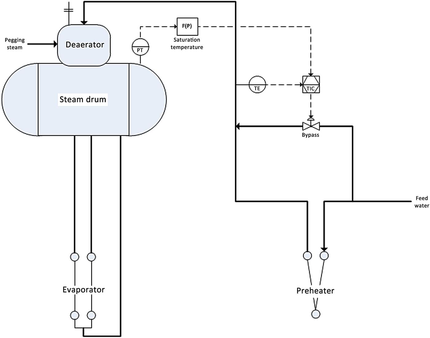
DA manufacturers typically suggest an approach temperature (difference between steam temperature and incoming feedwater temperature) into the DA tank in the range of 20–25°F. Under part load operation, the temperature of DA influent can encroach into this range thus risking premature release of O2 into the system. A simple partial bypass around all or part of the feedwater preheater is commonly employed to control the DA approach to the desired range.
14.3.7 Drum blowdown/blowoff
Operation of the HRSG with inappropriate water chemistry will generally lead to poor cycle performance and increased maintenance due to elevated corrosion rates. Most drum type HRSGs are equipped with dedicated connections for assisting the plant in maintaining the HRSG water chemistry within acceptable levels. These connections are the continuous blowdown (CBD) and the intermittent blowoff (IBO). While neither need be automated, as the plant may operate satisfactorily via direct operator control, both connections may be automated. The blowdown connection is easier and more efficiently controlled than the blowoff connection.
14.3.7.1 Continuous blowdown
The CBD connection is provided for the removal of dissolved solids (Ca+, Mg+, Na+, PO4+, Cl−, etc.) from the steam drum that, while generally in concentration levels of ppm/ppb, can individually or in thermodynamically favorable compounds precipitate out in the steam turbine, the condenser, or any other portion of the steam/condensate cycle leading to reduced performance (i.e., reduced heat transfer, increased pressure drop) and damaging mechanisms (e.g., stress corrosion cracking, under deposit corrosion, caustic gouging, acid corrosion, etc.).
The boiling process concentrates the dissolved solids carried into the HRSG via the boiler feedwater. The amount of CBD flow removed from the drum, which is always in service when the HRSG is operating, and thus “continuous,” is a function of the concentration in the feedwater entering the drum and the concentration allowed in the steam effluent. The chemical/phase equilibrium of each chemistry component (e.g., Na+), often termed the distribution ratio, defines the allowed concentration in the liquid phase relative to the steam phase. Via the measurement of the feedwater flow rate and concentration of a representative element/compound and the measurement of the drum concentration of the same compound, a required CBD flow rate may be determined. The CBD valve is then adjusted to pass the determined flow. Of note is the challenge in getting an accurate two-phase flow measurement, which is the case with the CBD (i.e., the saturated water will flash as it passes along the CBD piping).
14.3.7.2 Intermittent blowoff
The IBO is provided to allow a means of removing suspended solids from the drum water. Unlike dissolved solids, which are ions of specific compounds, suspended solids are typically organic material that is held in solution only as a result of dynamic/static forces within the bulk fluid overcoming the gravitational force otherwise imposed on the particulate. Typical boiler chemistry would introduce an agent that creates the necessary flocculation and agglomeration of the small particles into a larger chain of higher mass weight to the point that the particle falls out of suspension. The IBO operation is used to purge the system of these large compounds.
The frequency of the IBO operation is not as easy to define as the CBD. A measurement of particulate matter may be collected from the steam drum and compared to industry-recommended concentrations; however, these measurements are generally grab samples and not easily carried out in situ. In practice, the frequency of the IBO is determined over a period of time, allowing the system to pickle, and often turns out to be on the order of once a day for fairly pure condensate. Systems using less-pure water will require more frequent operation. Typically, the IBO is opened and a certain portion of the drum water allowed to be removed (e.g., 4 in. of drum level). The IBO is more often than not operated manually by the operator although a series of timers may be employed to automate the process.
14.3.8 Pressure control (automatic relief valve, control valve bypass)
When one talks about HRSG performance, production quantity and temperature at a certain pressure are the key parameters used to describe the system. While mass flow and final temperature are controlled or a function of the fundamental thermal design, an unfired (i.e., no duct burner) HRSG does not, in and of itself, control pressure beyond that described with a startup vent or bypass system. The steam produced by the HRSG flows into a pipe network that delivers the steam to a final consumer. The final user, or more correctly, the back pressure imposed by the final user on the piping network, defines the pressure at the HRSG outlet.
NOTE: Some auxiliary systems (e.g., duct burners) may have pressure control valves to regulate the fuel pressure being delivered to the burner system, and the BoP may employ a scheme that employs a duct burner within the HRSG to regulate a steam header pressure; however, these items are considered to be outside the scope of the intended discussion of this chapter.
The next two sections intend to address two specific applications of pressure control within the boiler proper: automatic relief valves and control valve bypasses.
14.3.8.1 Automatic relief valve(s)
In a certain sense, one can correctly state that the ASME required pressure safety valves (PSVs) do in fact control the HRSG pressure. The misnomer here is the word control. The PSVs limit or prohibit the pressure from exceeding a certain maximum pressure but in the essence of this chapter, the PSV does not serve as an automatic control. The operators cannot alter or adjust position or set-points while running the system.
The lifting of a PSV is a traumatic event for the operating system, causing significant process upsets beyond that already being encountered, which is causing the PSVs to lift. Of immediate concern to the PSV itself is that when the plug lifts off of the valve seat, there is potential for the high-pressure drop of the passing steam to cut and/or wear valve components resulting in leakage after the plug resets. This leakage reduces plant efficiency and creates potential safety concerns. In addition, the leakage will continue to erode the damaged area, further increasing the negative impacts until the unit must be taken offline and the valve repaired.
In an attempt to avoid the lifting of PSVs and avoid the consequences described in the previous paragraph, some facilities employ an automatic relief valve system. In order to open the vent valve or bypass valve with suitable speed so as to avoid lifting the mechanical valve, the automatic relief valve system is fitted with pneumatic actuators or in some rare instances hydraulic actuators. The intent is to have the automatic vent system open at a lower pressure than the PSV set-point, thus avoiding the previously described issues. It is important to note that the inclusion of an automated system does not negate the requirement for ASME-designed boilers to include the mechanical PSVs. Plant designers will often size the actuators associated with a steam bypass system to allow the bypass system to function as a pseudo automated relief system. A word of caution when being asked to supply a system capable of preventing the PSVs from lifting after a steam turbine trip: the pressure wave associated with the suddenly halted steam flow will move at the speed of sound back through the piping network. As one does not typically have a feedforward signal when the steam turbine will trip, it is very difficult to achieve the requested goal (i.e., PSVs will almost always lift before the bypass system can open to a suitable level) unless a very fast, high-pressure, expensive hydraulic system is employed.
14.3.8.2 Control valve bypass
Depending on the requirements of the overall process, the main feedwater control valve may be located within the boiler proper piping downstream of some of the heat transfer coils (i.e., downstream of economizer coil(s)). While the placement of the control valve at this position fulfills a process need, there is a potential undesirable effect. As the water side of the economizer coils may now be isolated, a relief valve must be employed to ensure that design pressures are not exceeded.
During startup, prior to the demand of feedwater to maintain drum level, the feedwater control valve will be closed subsequently isolating the economizers (i.e., check valve on inlet line and control valve between economizer and drum closed). When heat is introduced into the system, the water within the isolated coils will expand (specific volume increases with increasing temperature) and may result in very high pressures within the coils due to the incompressibility of the water. This is not encountered in every unit and has been shown to be strongly influenced by the general BoP startup sequence. However, one is often not knowledgeable of the final plant startup scheme during the design phase. In any sense, a small ball valve may be placed in parallel to the feedwater control valve with a demand open set-point at a pressure just below the set-point of the aforementioned economizer relief valve. The actuated ball valve thus serves a similar role as that described for the actuated relief valve only this time in a water service (Fig. 14.7).
