
Developing the optimum cycle chemistry provides the key to reliability for combined cycle/HRSG plants
Barry Dooley, Structural Integrity Associates, Southport, United Kingdom
Abstract
The cycle chemistry treatments and control on combined cycle plants influence a high percentage of the availability and reliability losses and safety issues experienced on these plants worldwide. As this is a very large and important area this chapter has four main parts. The first part briefly introduces the equipment and materials of construction and how heat recovery steam generator (HRSG) reliability depends on various protective oxides, the formation of which relates directly to the cycle chemistry treatments that are used in the condensate, feedwater, evaporator water, and steam. The second part delineates the main damage and failure mechanisms influenced by not operating with the optimum cycle chemistry treatments thus allowing the protective oxides to break down. This will include the main damage mechanisms of flow-accelerated corrosion, under-deposit corrosion, and those that occur in the phase transition zone of the steam turbine. The third part will describe the key analytical tools that have been developed to identify whether failure and damage will occur in combined cycle/HRSG plants due to nonoptimum cycle chemistry treatments and control aspects. This involves identifying the deficiencies in cycle chemistry control that are referred to as repeat cycle chemistry situations. The final part describes the six sequential processes needed to develop the optimum cycle chemistry for combined cycle/HRSG plants to avoid the major failure and damage mechanisms.
Keywords
Heat recovery steam generators (HRSG); Cycle chemistry; all-volatile treatment; phosphate treatment; film forming products (FFP); flow-accelerated corrosion (FAC); under-deposit corrosion (UDC); air-cooled condensers (ACC); steam turbine phase transition zone (PTZ)
Nomenclature
AVT(O) All-volatile treatment (oxidizing)
AVT(R) All-volatile treatment (reducing)
CACE Conductivity after cation exchange
FAC Flow-accelerated corrosion
FFAP Film forming amine product
IAPWS International Association for the Properties of Water and Steam
RCCS Repeat cycle chemistry situation
15.1 Introduction
The cycle chemistry treatments and control on combined cycle plants influence a high percentage of the availability and reliability losses and safety issues experienced on these plants worldwide. As this is a very large and important area this chapter has four main parts. The first part briefly introduces the equipment and materials of construction and how heat recovery steam generator (HRSG) reliability depends on various protective oxides, the formation of which relates directly to the cycle chemistry treatments that are used in the condensate, feedwater, evaporator water, and steam. The second part delineates the main damage and failure mechanisms influenced by not operating with the optimum cycle chemistry treatments thus allowing the protective oxides to break down. This will include the main damage mechanisms of flow-accelerated corrosion (FAC), under-deposit corrosion (UDC), and those that occur in the phase transition zone (PTZ) of the steam turbine. The third part will describe the key analytical tools that have been developed to identify whether failure and damage will occur in combined cycle/HRSG plants due to nonoptimum cycle chemistry treatments and control aspects. This involves identifying the deficiencies in cycle chemistry control that are referred to as repeat cycle chemistry situations (RCCS). The final part describes the six sequential processes needed to develop the optimum cycle chemistry for combined cycle/HRSG plants to avoid the major failure and damage mechanisms.
Combined cycle/HRSG plants operate across a wide range of temperatures and pressures. Multipressure drum-type HRSGs are coupled to high pressure (HP), intermediate pressure (IP), and low pressure (LP) steam turbines, but there are also a number of HRSGs with once-through HP or HP/IP circuits.
Mild and low-alloy carbon steels are used in the construction of the preheaters, economizers, and evaporators of HRSGs with high alloy chromium containing steels and austenitic stainless materials being used in superheaters, reheaters, and steam turbines. It is very rare to find copper alloys in the HRSGs but these alloys can be used in condensers and in older combined cycle plants that have external feedwater heaters. Protection against corrosion is always provided by the protective and passive oxides that grow on the surfaces of all this equipment and material.
In multipressure HRSGs the lower pressure and temperature circuits such as preheaters, economizers, and IP/LP evaporators are the major sources of corrosion products, which can be transported into the HRSG HP evaporator and then deposited on the heat transfer surfaces of the water/steam cycle. Corrosion is increased by the presence of impurities in the condensate, feedwater, and cooling water. In combined cycle/HRSG plants the major source of corrosion products is by single- and two-phase FAC.
Corrosion of copper alloys, if present in combined cycle plants, can lead to the transport of copper into the HRSG resulting in deposition on the HP evaporators and on the high pressure turbine. Some early combined cycle/HRSG plants also had feedwater heaters fed by extraction steam. The buildup of deposits in the steam generating tubes of the HP evaporators, in combination with the presence of impurities, can lead to UDC during operation, and be the locations of pitting during nonprotected shutdowns.
The carryover of impurities into the steam from the HRSG drums can lead to deposits in the steam turbine, and may lead to stress corrosion cracking and corrosion fatigue in the superheaters and steam turbines, and pitting during nonprotected or inadequate shutdown conditions.
Leaks in water-cooled condensers are the most common source of impurities, such as chloride and sulfate, entering the water/steam circuit, whereas air-cooled condensers (ACCs) are subject to low temperature FAC and can be a major source of high levels of corrosion products and air ingress.
One of the main purposes of good cycle chemistry is to provide protection through oxide formation on the internal steam/water touched surfaces, and to prevent and/or reduce corrosion and deposits in the steam/water circuit of these power plants. A combination of chemical techniques has to be used to achieve this and chemical conditioning can be applied to the condensate, feedwater, and evaporator water. Guidance limits have to be developed to control the corrosion processes mentioned previously. Alternatively, allowing the cycle chemistry and its control not to be optimum will lead to major availability and reliability problems as outlined previously, and can result in safety issues for plant staff.
15.2 Optimum cycle chemistry treatments
For the development of optimum cycle chemistry it is important to note that the complete cycle of the combined cycle plant must be considered. Most often the cause of the cycle chemistry-influenced failure and damage mechanisms in a particular section or circuit does not originate at that location. For instance corrosion products from the LP and IP circuits can be transported into the HP evaporator and deposit. Also contaminants in the evaporator originating in the condensate can be carried over into the steam turbine.
A quick “tour” of the cycle chemistry utilized for combined cycle plants follows. This is an overview to provide an introduction of some key features required for the cycle chemistry control of power plants, and the nomenclature will be used throughout the chapter.
The first requirement is for high purity feedwater recycled from the condenser, or added as makeup. The purity is monitored by measurement of the conductivity after cation exchange (CACE) (which used to be called cation conductivity) of the condensate, feedwater, evaporator water, and steam. These measurements include contributions from impurities and corrosive species such as chloride, sulfate, carbon dioxide, and organic anions. The higher the temperature and pressure of operation, the higher the purity of water required to prevent corrosion and, thus, the lower the CACE allowed.
The chemistry of the condensate and feedwater is critical to the overall reliability of HRSG plants. Corrosion takes place in the feedwater of HRSG plants (preheaters and economizers), and the resulting corrosion products flow into the HRSG evaporators, where they deposit on heat transfer areas. These deposits can act in the HRSG evaporator as initiating centers for many of the tube failure mechanisms, and in the steam turbine as a source of either efficiency losses or blade/disk failures. The choice of feedwater chemistry depends primarily on the materials of construction and secondly on the feasibility of maintaining purity around the water/steam cycle.
Most often a volatile alkalizing agent, usually ammonia, is added to the condensate/feedwater to increase the pH. Alternatively a neutralizing amine can be added in place of ammonia. A film forming product (FFP) can be added instead of the ammonia or neutralizing amine. FFPs include film forming amines and film forming compounds that do not contain an amine. These FFP are usually proprietary compounds where the exact composition is not known by the user and most often they are supplied as blends with a neutralizing amine and then referred to as a film forming amine product. As of 2016, much work is being conducted internationally to provide guidance on these FFPs.
15.2.1 Condensate and feedwater cycle chemistry treatments
There are three main established variations of volatile conditioning that can be applied to the condensate and feedwater:
15.2.1.1 All-volatile treatment (reducing) [1]
All-volatile treatment (reducing) or AVT(R) involves the addition of ammonia or an amine, FFP, blend of amines of lower volatility than ammonia and a reducing agent (usually hydrazine or one of the acceptable substitutes such as carbohydrazide) to the condensate or feedwater of the plant. In combination with a relatively low oxygen level (from air in-leakage) of about 10 ppb (μg/kg) or less in the condensate (usually measured at the condensate pump discharge [CPD]), the resulting feedwater will have a reducing redox potential (usually measured as a negative oxidation-reduction potential [ORP]). Higher levels of oxygen (>20 ppb [μg/kg]) (due to high air in-leakage) will usually preclude generation of the reducing environment, but are often incorrectly accompanied by excessive dosing of the reducing agent. AVT(R) is most often used to provide protection to copper-based alloys in mixed-metallurgy feedwater systems in fossil plants. In multipressure HRSG systems, AVT(R) should not be used in these cycles due to concerns for single-phase FAC, and because the corrosion product levels in the feedwater would be most likely to exceed 2 ppb (μg/kg). Reducing agents should not be used in combined cycle/HRSG plants.
15.2.1.2 All-volatile treatment (oxidizing) [1]
All-volatile treatment (oxidizing), or AVT(O), has emerged since the 1990s as the much preferred treatment for feedwater systems that only contain all-ferrous materials (copper alloys can be present in the condenser). In these cases, a reducing agent should not be used during any operating or shutdown/layup period. Ammonia or an amine, FFP, blend of amines of lower volatility than ammonia is added at the CPD or condensate polisher outlet (if a polisher is included within the cycle). This is the treatment of choice for multipressure combined cycle/HRSG plants that have no copper alloys in the feedwater. In combined cycle/HRSG plants with relatively good control of air in-leakage (oxygen levels in the range 10–20 ppb (μg/kg)), the resulting feedwater will yield a mildly oxidizing positive ORP. Under optimum conditions, a multiple pressure combined cycle plant should be able to operate with corrosion product levels of total Fe<2 ppb (μg/kg) in the feedwater and <5 ppb (μg/kg) in the drums.
15.2.1.3 Oxygenated treatment
Application of oxygenated treatment (OT) [1] in combined cycle/HRSG plants is much rarer than in conventional fossil plants, but often it is found that the use of AVT(O) with low levels of oxygen (<10 ppb (μg/kg)) on these plants does not provide sufficient oxidizing power to passivate the very large internal surface areas associated with preheaters; LP, IP, and HP economizers; and LP evaporators, especially if a deaerator is included in the LP circuit. In these cases, oxygen can be added at the same level as for conventional recirculating cycles (30–50 ppb (μg/kg)). This is the feedwater of choice for conventional fossil units with all-ferrous feedwater heaters and a condensate polisher and with an ability to maintain a CACE of <0.15 μS/cm under all operating conditions. Under optimum conditions, a multiple pressure combined cycle plant the total Fe should be <1 ppb (μg/kg) in the feedwater and <5 ppb (μg/kg) in each of the drums.
15.2.1.4 Film forming products
The application and use of FFP in conventional fossil and combined cycle/HRSG plants is increasing worldwide. They work in a different way than the conventional treatments by being adsorbed onto metal oxide/deposit surfaces thus providing a physical barrier (hydrophobic film) between the water/steam and the surface. There are three main chemical substances that have been used historically: octadecylamine (ODA), oleylamine (OLA), and oleylpropylendiamine (OLDA). As well as these compounds the commercial products contain other substances, such as alkalizing amines, emulsifiers, reducing agents, and dispersants. There is currently much confusion about their application for both normal operation and shutdown/layup, and there is no international guidance on deciding whether to use an FFP or whether it will provide a benefit to the plant. This situation will change in 2016 when the International Association for the Properties of Water and Steam (IAPWS) publishes the first FFP guidance [2].
There are some basic international rules for the application of these condensate/feedwater treatments. The all-volatile treatments (AVT(R), AVT(O), or OT) have to be used for once-through boilers and are used without any further addition of chemicals in the boiler or HRSG evaporators. AVT(R), AVT(O), or OT can also be used for drum boilers of conventional fossil plants or combined cycle/HRSGs without any further addition of chemicals to the boiler/HRSG drum. However, impurities can accumulate in the boiler water of drum-type HRSGs and it is necessary to impose restrictive limits on these contaminants as a function of drum pressure both to protect the boiler from corrosion and to limit the amount of impurities possibly carried over into the steam [3], which could put at risk the superheaters, reheaters, and steam turbines. It is recognized that AVT has essentially no capability to neutralize or buffer feedwater/boiler water dissolved solids contamination. Ammonia is a rather poor alkalizing agent at high temperatures, offering very limited protection against corrosive impurities.
15.2.2 HRSG evaporator cycle chemistry treatments [4]
For some drum-type boilers, the addition of solid alkalizing agents to the boiler/HRSG water may be necessary in order to improve the tolerance to impurities and reduce the risk of corrosion. The alkalizing agents that can be used for this are trisodium phosphate (TSP) (phosphate treatment (PT)) or sodium hydroxide (caustic treatment (CT)) used alone. The two can also be used in combination. The amounts of sodium hydroxide added have to be strictly limited to avoid excessively alkaline conditions, which can result in a UDC mechanism (caustic gouging [CG]), which destroys the protective oxide layer in the boiler or HRSG evaporator. The amounts of both sodium hydroxide and TSP added to the cycle also have to be controlled to avoid an increase of carryover of these conditioning chemicals into the steam, possibly putting the superheaters and turbines at risk [3].
Boiler and HRSG evaporator treatments are critical to the overall reliability of conventional fossil and HRSG plants as they control and influence not only the major tube failure mechanisms but also a number of damage mechanisms in the steam turbine.
15.2.2.1 Phosphate treatment
Phosphates of various types have been the bases of the most common boiler/HRSG evaporator treatments worldwide. However, historically there has been a multitude of phosphate compounds and mixtures blended with other treatment philosophies, which has resulted in a wide range of control limits for the key parameters (pH, phosphate level, and sodium-to-phosphate molar ratio) and a number of reliability issues. Some of the traditional PTs such as congruent phosphate treatment (CPT), coordinated PT, and equilibrium phosphate treatment (EPT) have been used since the 1960s across the fleet of conventional fossil boilers and HRSG evaporators, sometimes successfully, sometimes resulting in tube failures and other problems. For instance, the use of CPT, where mono- and/or disodium phosphate are used to develop operating control ranges below sodium-to-phosphate molar ratios of 2.6:1, has resulted in serious acid phosphate corrosion (APC) in many conventional fossil boiler waterwalls and HRSG HP evaporators that have heavy deposits and have experienced phosphate hideout.
More recently, since the 1990s, consolidated good operating experiences worldwide have led to the recognition that TSP should be the only phosphate chemical added to a boiler/HRSG, and that the operating range should be bounded by sodium-to-phosphate molar ratios of 3:1 and TSP+1 ppm (mg/kg) NaOH with a pH above 9.0 and a minimum phosphate limit above 0.3 ppm (mg/kg). It should be emphasized that the 0.3 ppm (mg/kg) level is regarded as a minimum and that better protection will be afforded by operating at as high a level of phosphate as possible without experiencing hideout or exceeding the steam sodium limits.
PT can be used in a wide range of drum units up to high pressures (2800 psi, 19 MPa), so it is often the only alkali treatment available because CT is not suggested for use above 2400 psi (16.5 MPa). However, it will be recognized that phosphate hideout and phosphate hideout return become more prevalent with increasing pressure. Phosphate hideout is the loss of phosphate from the boiler/evaporator water on increasing drum pressure, and hideout return is the return of the phosphate to solution on decreasing pressure. Hideout and hideout return are therefore always associated with large swings of pH causing boiler/evaporator control problems, but if only TSP is used, then no harmful corrosion reactions can be initiated as was experienced with CPT using sodium-to-phosphate molar ratios below 2.6:1.
For multipressure HRSGs, PT can also be used in each of the pressure cycles, but use of PT here is for different reasons depending on the pressure of the circuit. At high pressure, the addition of TSP is basically to assist in addressing contamination in the same way as for conventional fossil plants. In the lower pressure circuits, with temperatures below 480°F (250°C), PT is used to help control two-phase FAC much as CT is used in these circuits. Of course neither solid alkali is used in the LP evaporator in units where the LP drum feeds the IP and HP feedpumps and attemperation.
15.2.2.2 Caustic treatment
Caustic treatment (CT) can be used in conventional fossil and HRSG drum-type boilers to reduce the risk of UDC, and in HRSGs for controlling FAC in the lower-pressure circuits, where all-volatile treatment has proved ineffective, or where PT has been unsatisfactory due to hideout or has experienced difficulties of monitoring and control.
The addition of sodium hydroxide to the boiler/evaporator water has to be carefully controlled to reduce the risk of CG in the HP evaporator and carryover into the steam, which could lead to damage of steam circuits and turbine due to stress corrosion cracking. Of primary risk are austenitic materials, stellite, and all steels with residual stresses (e.g., welds without heat treatment) in superheaters, steam piping and headers, turbine control and check valves, as well as components in the steam turbine. CT is easy to monitor, and the absence of the complications due to the presence of phosphate allows online conductivity and CACE measurements to be used for control purposes.
15.3 Major cycle chemistry-influenced damage/failure in combined cycle/HRSG plants
15.3.1 Overview of cycle chemistry-influenced damage/failure mechanisms
It is not surprising that because the cycle chemistry “touches” all the parts of a generating plant that it controls the availability and reliability of these plants. It has been suggested since the 1990s and early 2000s that the cycle chemistry influences about 50% of all the failure and damage mechanisms in conventional fossil plants, but because of the added complexity of combined cycle/HRSG plants with multiple pressures this number may be as high as 70%. The statistics of cycle chemistry-influenced failure and damage mechanisms in combined cycle/HRSG plants have changed very little since at least the early 1990s. These can be categorized as follows:
– FAC in LP and IP evaporators; LP, IP, and HP economizers (single- and two-phase) (see detailed listing in Section 15.3.1.1)
– Corrosion fatigue in LP evaporators and economizers
– UDC in HP evaporators of both vertical and horizontal gas path HRSGs (mainly hydrogen damage (HD) but APC and CG have also occurred) (see Section 15.3.1.3)
– Pitting (often evidenced as tubercles in pressure vessels (drums, deaerators))
• FAC in ACCs (with main damage by two-phase FAC at ACC tube entries in upper ducts) (see Section 15.3.1.1)
• Steam turbine damage (see Section 15.3.1.2)
– Corrosion fatigue of blades and disks in the PTZ of the LP turbine
– Stress corrosion cracking (SCC) of blades and discs in the PTZ of the LP turbine
– Pitting on blade and disc surfaces
One very important note is that although FAC and UDC mechanisms occur at opposite ends of the HRSG, they are linked by the corrosion products generated by the FAC mechanisms in the low pressure parts of the HSRG, which subsequently transport to, and deposit in, the HP evaporator tubing where they form the basis of the UDC damage mechanisms. This link forms the main focus of the cycle chemistry assessments in HRSGs, which identify the precursors or active processes, which left unaddressed, will eventually lead to failure/damage by one or both mechanisms. Acting proactively will remove the risk for both, and it is clear that avoiding FAC and the associated increased corrosion in the LP circuits essentially ensures that UDC will not occur. The mechanisms of FAC, UDC, and deposition are discussed in three of the subsections following.
15.3.1.1 Flow-accelerated corrosion in combined cycle/HRSG plants
FAC occurs due to the accelerated dissolution of the protective oxide (magnetite) on the surface of carbon steel components caused by flow. For combined cycle/HRSG plants a detailed review of the FAC mechanism is available [5] and is illustrated in Fig. 15.1. The concentration in this chapter is to indicate that the overall optimum cycle chemistry for these plants must first include the cycle chemistry influences of single- and two-phase FAC as outlined in Section 15.6.

15.3.1.2 FAC in combined cycle/HRSGs
All the HRSG components within the temperature range 212–572°F (100–300°C) are susceptible to FAC, which involves both the single- and two-phase variants predominantly in low temperature (LP, IP, and HP) economizers/preheaters and evaporators (tubes, headers, risers, and drum components such as belly plates). The same components can also be susceptible to FAC in HRSG designs where the nominal HP evaporator circuit operates for significant periods of time at temperatures <572°F (300°C) (e.g., the HP evaporators in older dual-pressure HRSGs, HRSGs where there is only one pressure stage, and high pressure evaporator circuits in plants running for extended periods at low load with sliding pressure operation). A quite comprehensive listing of locations of FAC in combined cycle/HRSGs is provided in Table 15.1.
Table 15.1
Locations of FAC in combined cycle/HRSG plants (typical tube and header materials, and range of operating temperatures)
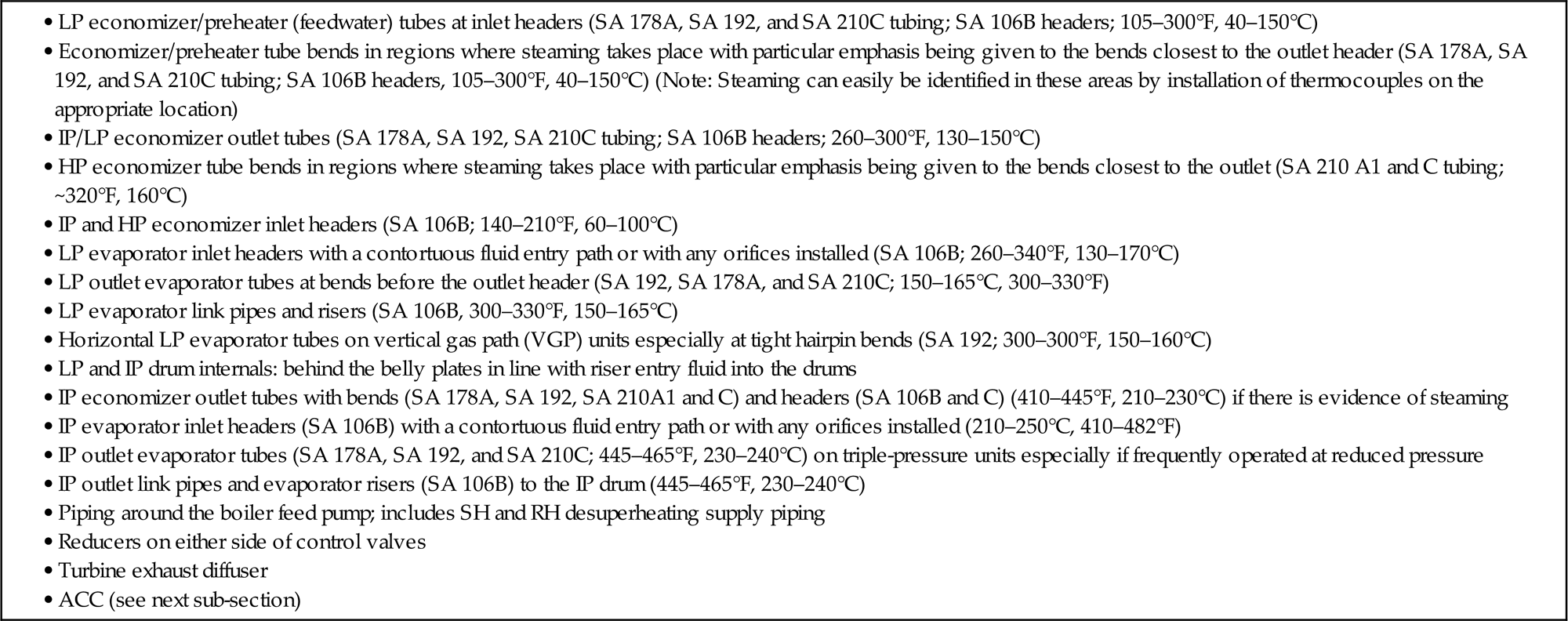
Source: Adapted from R.B. Dooley, R.A. Anderson, Assessments of HRSGs – trends in cycle chemistry and thermal transient performance, PowerPlant Chem. 11 (3) (2009) 132–151, [6].
The appearances of single- and two-phase FAC are illustrated in Fig. 15.2.

The corrosion products released by the FAC mechanism in these circuits and by corrosion of the nonpassivated lower-temperature/pressure circuits are transported away from the corrosion site and can eventually reach the HP evaporator and deposit on the internal tubing surfaces.
15.3.1.3 Flow-accelerated corrosion in air-cooled condensers
An increasing number of combined cycle/HRSG plants worldwide are equipped with ACC. Operating units with ACCs at the lower regimes of pH provided in IAPWS guidance documents will result in serious corrosion and FAC in the ACC tubes, most predominantly at the entries to the cooling tubes [7]. The potential for ACC to act as a major source of corrosion products needs to be considered in developing the optimum cycle chemistry control for an HRSG plant. Whether this is occurring can easily be determined by monitoring the total iron at the condensate pump discharge (CPD) [8]. To rectify the FAC situation, it will be necessary to conduct a series of tests with gradually increasing levels of pH while monitoring total iron. A condensate/feedwater pH of around 9.8 (as measured at 77°F, 25°C) will be needed to reduce the FAC to low enough levels to observe total iron values at the CPD of around 5 ppb (μg/kg) or less [7]. If the total iron values cannot be reduced to less than 5 ppb (μg/kg) by increasing the pH, then there may be a requirement to include a 5 μm absolute condensate filter or a prefilter prior to a condensate polisher if included in the cycle. Condensate polishing is not universal on plants with ACC.
Operating with elevated pH to control low temperature FAC in the ACC will also assist in addressing two-phase FAC in the other areas of the HRSG. For plants operating in the oxidizing mode, AVT(O) or OT, the customization can be useful to improve the conditions in the two-phase regions but will be of little relevance for the single-phase flow regions because, in the absence of contaminant anions, corrosion is suppressed to a very low level across the pH range 7–10.
The cycle chemistry-influenced damage in ACC can be best described through an index for quantitatively defining the internal corrosion status of ACC. This is known by the acronym DHACI (Dooley Howell ACC Corrosion Index) [7]. The index separately describes the lower and upper sections of the ACC, as described in the following paragraph.
The index provides a number (from 1 to 5) and a letter (from A to C) to describe/rank an ACC following an inspection. For example, an index of 3C would indicate mild corrosion at the tube entries, but extensive corrosion in the lower ducts. An example for the upper ACC section (upper duct/header, ACC A-frame tube entries) is shown in Fig. 15.3. An example for the lower ACC section (turbine exhaust, lower distribution duct, risers) is shown in Fig. 15.4.


The DHACI can be used to describe the status of a particular ACC in terms of its corrosion history and is a very useful means of tracking changes that occur as a result of making changes in the cycle chemistry. A plant that has a relatively poor rating for corrosion at a steam cycle pH of 8.5–8.8 (e.g., 4C) may increase the pH to 9.4–9.6, and determine whether this change improves its rating (e.g., 3B). A poor rating (e.g., 4B) indicates the need to consider options to reduce the corrosion rate especially in the tube entry areas.
Additionally, the index provides a convenient tool for comparison between different units. This can aid in determining whether some cycle chemistry factor in effect at one station, e.g., use of an amine rather than ammonia, is yielding better results.
15.3.1.4 Steam turbine phase transition zone failure/damage
Impurities in the steam from the HRSG may cause deposits and corrosion in steam turbines and thus the steam purity controls most corrosion processes and is vital to combined cycle plant reliability. These problems can usually be avoided by following the guidance in the IAPWS Steam Purity Technical Guidance Document (TGD) [9], which needs to be compatible with the condensate, feedwater, and evaporator chemistries discussed in Sections 15.2.1 and 15.2.2.
The four most important corrosion-related failure/damage mechanisms in the low pressure (LP) steam turbine are deposition, pitting, corrosion fatigue, and stress corrosion cracking. The local steam environment determines whether these damage mechanisms occur on blade and disk surfaces. The PTZ, where the expansion and cooling of the steam leads to condensation, is particularly important. A number of processes that take place in this zone, such as precipitation of chemical compounds from superheated steam, as well as deposition, evaporation, and drying of liquid films on hot surfaces, lead to the formation of potentially corrosive surface deposits. Understanding the processes of transport, droplet nucleation, the formation of liquid films on blade surfaces, and concentration of impurities is vital to understanding how to avoid corrosion-related damage, and to improve unit efficiency/capacity [9].
The following two cycle chemistry operating regimes are identified as relevant to steam turbine corrosion. Of course, adequate materials properties (composition, structure, internal stresses, etc.) and design (temperature, stresses, crevices, etc.) also play essential roles.
• The dynamic environment during turbine operation. These are the local conditions formed by the condensation of steam as it expands through the PTZ of the turbine, and by the deposition of salts, oxides, and other contaminants directly onto steam path surfaces.
• The environment produced during shutdown. These are the conditions that occur during unprotected shutdown when oxygenated moist/liquid films form on steam path surfaces as a result of hygroscopic effects. These films are directly caused by inadequate shutdown practices adopted by the turbine operator. They can lead to pitting, which is most often the precursor to the corrosion mechanisms.
Thus, if adequate layup protection (dehumidified air (DHA)) is not provided, serious corrosion damage may occur even with the best operating chemistry, materials, and design, and with only few major deposits. It is recognized that pitting can possibly also initiate during operation in crevice areas such as blade attachments.
Impurities can enter the steam from the HRSG by the following processes:
• drum (LP, IP, HP) carryover of HRSG evaporator water
• volatility in evaporating evaporator water
• injection of feedwater into the superheater or reheater for attemperation
For a complete description of the chemistry in the PTZ of the LP steam turbine the reader is referred to the IAPWS Steam Purity TGD [9]. This includes the details on droplet nucleation, liquid film formation on turbine parts, deposition of oxides and impurities on surfaces, and how inadequate shutdown practices results in pitting. The major failures mechanisms of corrosion fatigue and stress corrosion cracking are initiated at pits so this sequential process is most important.
15.3.1.5 Combined cycle/HRSG steam purity limits
For combined cycle/HRSG plant with condensing turbines operating with superheated steam the following guideline limits (Table 15.2) are suggested by IAPWS [9]:
Table 15.2
Steam purity for condensing turbines with superheated steam in combined cycle/HRSG plants, applicable for steam temperature below 1112°F, 600°C
| Parameter | Unit | Normal/target values |
| Conductivity after cation exchange @ 25°C | μS/cm | <0.20 |
| Sodium as Na | ppb, μg/kg | <2 |
| Silica as SiO2 | ppb, μg/kg | <10 |
Source: IAPWS, Technical Guidance Document: Steam Purity for Turbine Operation (2013). Available from: <http://www.iapws.org>.
These limits are considered as the normal operating values during stable operation to avoid the steam turbine damage mechanisms and are consistent with long-term turbine reliability.
15.3.1.6 Steam purity for startup
In the case of a warm start, the values for normal operation (Table 15.2) should be attained within 2 hours, and in the case of a cold start within 8 hours. During startup, the impurity concentrations should show a decreasing trend.
Steam should not be sent to the turbine if the concentration of sodium exceeds 20 ppb (μg/kg). The immediate need at startup to ensure compliance with this limit requires a sodium monitor for steam, as specified in the IAPWS Guidance on Instrumentation for Cycle Chemistry [10].
Steam should not be sent to the turbine if the CACE exceeds 0.5 μS/cm. Allowance may be given to possible contributions from carbon dioxide and for sodium in units that only use TSP in the evaporator water. The actual contribution of carbon dioxide must be measured and regularly verified for the specific plant. Degassed CACE can help to estimate the contribution of carbon dioxide.
15.3.1.7 Unit shutdown limits
In addition to operating with a set of normal and action levels it is also necessary to define a set of cycle chemistry conditions under which a unit must be shut down because of severe contamination. Shutdown conditions usually involve defining a steam CACE that indicates serious acidic contamination. Typically, a value of 1 µS/cm can be used under conditions that coincide with other upset conditions in the steam/water cycle. Carbon dioxide from air in-leakage or certain conditioning agents may warrant a less stringent CACE.
15.3.1.8 Failure/damage mechanisms in HRSGs: highlighting the under-deposit corrosion mechanisms
The three UDC mechanisms in HRSGs, i.e., HD, APC, and CG, occur exclusively in HP evaporator tubing [11–13], and all require relatively thick porous deposits and a chemical (either a contaminant or nonoptimized treatment) concentration mechanism within those deposits. UDC damage can occur early in the life of an HRSG due to the inverse relationship between deposit loading/thickness and the severity of the chemical excursion.
For HD, the concentrating corrodent species is most often chloride that enters the cycle through condenser leakage (especially with seawater or brackish water cooling) and via slippage into demineralized makeup water in water treatment plants where ion exchange resins are regenerated with hydrochloric acid.
APC relates to a plant using phosphate blends that have sodium-to-phosphate molar ratios below 2.6 and/or the use of CPT using either or both mono- or disodium phosphate.
CG involves the concentration of NaOH used above the required control level within caustic treatment, or with the use of coordinated phosphate with high levels of free hydroxide, or the ingress of NaOH from improper regeneration of ion exchange resins or condenser leakage (freshwater cooling).
15.3.1.9 Deposition in HRSG HP evaporators
Deposition and the UDC mechanisms can occur on both vertical and horizontal HRSG HP evaporator tubing. On vertical tubing the deposition usually concentrates on the internal surface (crown) of the tube facing the gas turbine (GT). It is nearly always heaviest on the leading HP evaporator tube in the circuit as these are the areas of maximum heat flux. Area of concentration can be the tube circuits adjacent to the side walls or to the gaps between modules due to gas bypassing. The UDC mechanisms usually occur in exactly the same areas. On horizontal tubing in VGP HRSGs both deposition and the UDC mechanisms occur on the ID crown facing toward or away from the GT. Damage occurs on the side facing away from the GT when poor circulation rates, steaming, or steam blanketing lead to stratification of water and steam and subsequent heavy deposition in a thin band along the top of the tubing corresponding to the steam–water interface during service. When circulation is adequate, the UDC mechanisms occur on the internal crown of the lower tube surface facing the GT.
The UDC mechanisms of HD and CG have been well understood since the 1970s, and the acid phosphate mechanism since the early 1990s [14]. But until about 2015 the understanding of how the initiating deposition takes place in HRSG tubing has been less well understood as is the level of deposits necessary for these mechanisms to initiate by concentration within thick deposits.
Until about 2015 there have not been any comprehensive studies to characterize and quantify the critical level of deposits forming in HRSG HP evaporator tubes. Initial published data from over 100 HRSGs worldwide has led to a new understanding on where to sample and how to analyze HRSG tubes for deposits and how to determine if the HRSG needs to be chemically cleaned [15]. This is now published in an IAPWS TGD [16] and the deposit map is shown in Fig. 15.5.

Examples of deposit loadings from over 100 HRSGs worldwide have been plotted to develop the new deposit map shown in Fig. 15.5. Plants included cover a very wide range of HRSGs from 17 HRSG manufacturers with HP drum pressures spanning the range 1300–2200 psi (8.9–15.2 MPa) and with deposits up to 125 g/ft2 (136 mg/cm2). Full coverage of this is included in the IAPWS TGD [16].
Some general comments from the IAPWS document are made here about the three colored cloud regions of Fig. 15.5:
• It should be first noted that the deposit map is only applicable to HRSG HP evaporator pressures above about 1100 psi (7.6 MPa) relative to UDC mechanisms in HRSGs.
• The green cloud represents deposit levels from HRSG plants operating with optimum chemistries and generally meeting the total iron corrosion products levels. These generally have deposit densities/loadings below ~11 g/ft2 (12 mg/cm2). The color of the internal surfaces under these optimum chemistry conditions is generally red/brown, indicative of transported hematite from the lower-pressure circuits. Importantly, in no case was concentration identified or were reaction products observed in the deposits near to the tube interface. This suggests that concentration reactions of chemical species, such as chloride, within the deposits cannot take place when the level of deposition is so low, and that the risk therefore for UDC for the HRSG will be low.
• The yellow cloud generally represents the deposits in the HP evaporator in plants not using the optimum chemistry conditions such as by the use of reducing agents. This occurs even for units with very low operating hours (<10,000 hours). The internal surfaces under these chemistry conditions are generally much darker and in most cases black.
• Toward the top of the yellow cloud and always in the red cloud there is evidence for concentration being identified or reaction products being observed in the deposits near to the tube interface. The internal tube surfaces are most often black, indicative of transported magnetite. Most significantly, no deposition data for any of these units has been measured in the green cloud. Unfortunately very few of these plants sampled have accurate total iron data to be able to see the elevation above the rule of 2 and 5 (total iron corrosion products less than 2 ppb (μg/kg) in the feedwater and less than 5 ppb (μg/kg) in each drum).
• Clearly as HP evaporator deposits become thicker and exceed about 20–25 g/ft2 (25 mg/cm2) (top of the yellow band and into the red band in Fig. 15.5) they become more porous and thus become more susceptible to concentration mechanisms and corrosion reactions at the base of the deposits next to the tube surface. These are the exact concentration processes that initiate UDC and should be avoided. Thus if HP deposit analyses indicate levels within the red cloud then the HRSG operator should consider chemical cleaning.
• It must be noted that there are no solid lines between the clouds indicating that the boundaries are only for guidance.
• The difference between deposit loadings in HRSGs using the optimum chemistry (according to the IAPWS TGDs [1 and 4]) as compared to the deposit loadings with nonoptimum chemistry is very clear. The difference between deposits that do not have concentration or corrosion reaction products and those that do is also very clear with careful metallography as described in the IAPWS TGD [16].
This new concept contained within the background of Fig. 15.5 of avoiding deposits that are thick enough to allow concentration provides the first step of avoiding UDC. The readers should be aware that the selection of the right cleaning procedure is not always easy and simple, and that a certain caution and pretest is advised. The results from the metallurgical analyses of the deposits can be used to identify the chemicals (solvents) that should be used in a chemical cleaning process if the analyses indicate that cleaning is needed.
15.4 Developing an understanding of cycle chemistry-influenced failure/damage in fossil and combined cycle/HRSG plants using repeat cycle chemistry situations
The understanding of the cycle chemistry-influenced failure and damage mechanisms in the steam/water circuits of conventional fossil and combined cycle/HRSGs is very advanced, and has been known and documented since the 1980s. In spite of this, chemistry-influenced damage and the associated availability losses due to deficient chemistry practices are often enormous. Damage and component failure incidents persist, in both conventional fossil and combined cycle units. It is thus very clear that the approaches taken by organizations operating combined cycle/HRSG plants to prevent such damage are frequently unsuccessful. Similarly, conventional fossil industry usage of the response methodology by which chemistry-related damage events are reacted to (identification of the mechanism, assessment of the root cause, and implementation of actions to stop the mechanism) is often ineffective.
Analysis in 2008 [17] of past cycle chemistry assessments and damage/failure reviews in over 100 organizations worldwide led to a very interesting new concept to prevent damage/failure proactively. This involves identifying RCCS. These, which can be regarded as the basics of cycle chemistry, are allowed to continue by the chemistry or operating staff or are imposed on the plant/organization as a consequence of inadequate management support for cycle chemistry.
The first subsection introduces the reader to RCCS while the second provides information on the application of the RCCS analysis to 170 plants worldwide since 2008. This analysis in total from over 250 plants worldwide confirms that the process can be used proactively to identify cycle chemistry deficiencies that if not addressed will lead to future failure/damage of the types delineated in Section 15.3.
15.4.1 Development of repeat cycle chemistry situations
The analysis conducted in 2008 identified two key features that related to why and how cycle chemistry influenced failure/damage occurred in conventional fossil and combined cycle/HRSG plants. From the mechanism aspect the first shows that cycle chemistry-influenced failure/damage involves the breakdown of the protective oxide that grows on all fluid-touched surfaces. This could involve cracking, fluxing, dissolving, and solubilizing of the oxide layers as well as deposition of corrosion products (oxides) on the surfaces. From the viewpoint of organizational or management aspects of the cycle chemistry and its control, it became clear that every cycle chemistry failure/damage incident can be related backwards in time to multiples of RCCS that were not recognized or properly addressed and allowed to repeat or continue. In some cases the chemistry staff had not recognized the importance of the situation and allowed it to continue. In other cases the chemistry staff recognized the importance, but was not successful in convincing the management (either plant or executive) that action was required. In many cases the management has delayed action or has not provided the necessary funds to resolve the situation. In doing this type of retroactive analysis it very quickly became obvious that plants/organizations can get away with having one or two RCCS, but once this number increases then failure/damage was a certainty.
In 2008, ten RCCS were identified that were very commonly associated with preventable cycle chemistry-related damage in conventional fossil and combined cycle plants. After using the RCCS analysis at 177 plants worldwide since 2008, the categories have remained the same but it has become clear that there are multiple subcategories. To assist the readers in understanding the RCCS and whether they exist in their plants, the following provides a few notes on some of the most important categories. Some examples of a few case studies are provided later to further illustrate this concept.
This RCCS analysis is very powerful in assisting with root cause analysis, in identifying where cycle chemistry failure/damage will occur in the future, and where improvements should be made. It has also been used internationally to identify where international research and guidance is necessary.
15.4.1.1 Corrosion products
Categories include the following: corrosion product levels are not known or monitored, the levels are too high and above international guideline values [8], inadequate and/or not sufficient locations being monitored, sampling conducted at the same time/shift each time, and using techniques with incorrect detection limit; a most common feature is monitoring the soluble part only by not digesting the sample. A key easy-to-observe verification aspect of this RCCS is black deposits in the steam and water sampling troughs for combined cycle/HRSG units on AVT(O), or red deposits for units on AVT(R).
15.4.1.2 Conventional boiler/evaporator deposits [16]
Categories include the following: HRSG HP evaporator samples have not been taken for analysis, there is no knowledge of deposits and deposition rate in HP evaporators, samples taken but not analyzed comprehensively according to the IAPWS TGD [16], deposits excessive and exceed criteria to chemical clean, the HP evaporator deposits are not linked with chemistry in the lower-pressure circuits or to the levels of transported total iron [8], the HP evaporator has been sampled and needs cleaning according to IAPWS criteria [16] but management delayed or canceled.
15.4.1.3 Drum carryover
Categories include the following: measurement of carryover [3] not conducted since commissioning, not conducted even on units with PTZ problems, not aware of simple process to measure carryover [3], saturated steam samples not working or nonexistent, samples taken are not isokinetic.
15.4.1.4 Continuous online cycle chemistry instrumentation [10]
Categories include the following: installed and operating instrumentation is at a low percentage compared to IAPWS (a normal level is between 58 and 65%); too many out of service, not maintained or calibrated; instruments are not alarmed for operators and many are shared by multiple locations and not/never switched; plant relies on grab samples to control plant (1–3 times per day/shift); the instrumentation most often missing is CACE (cation conductivity) and sodium on main or HP steam and conductivity (specific conductivity) on makeup line to condenser.
15.4.1.5 Challenging the status quo
Categories include the following: no change in chemistry since commissioning; using incorrect or outdated guidelines; continuing to use reducing agents in combined cycle/HRSGs and thus risking or experiencing single-phase FAC; continuing to use the wrong phosphate treatment (usually not using only TSP); not having a chemistry manual for the unit, plant or organization; incorrect addition point for chemicals (most often reducing agent with AVT(R)); not questioning use of proprietary chemical additions (phosphate blends, amines, FFP) and therefore not knowing the composition of chemicals added to the unit/plant; not determining through monitoring the optimum feedwater pH to prevent/control FAC.
15.4.1.6 Shutdown/layup protection
Categories include the following: unit/plant has no equipment for providing shutdown protection (nitrogen blanketing, DHA), equipment present but not used or inoperable/not maintained, poor/no operator procedures, only partial protection applied (HRSG vs feedwater), no DHA provided for the steam turbine shutdowns.
15.4.1.7 Contaminant ingress
Categories include the following: no assessment of risk; inadequate instrumentation and alarms (especially for seawater cooled plants); operators allow exceedances of control and shutdown levels; chemists and/or operators compromise limits to plant ability (make high readings acceptable), or make up (invent) normal and action levels which have no technical relevance; no comprehensive procedures to deal with contaminant ingress.
15.4.2 Using RCCS to identify deficiencies in cycle chemistry control of combined cycle/HRSG plants
Between 2008 and 2016 the RCCS analysis has been applied during 177 plant assessments. Of these, 112 were at conventional fossil plants and 65 were combined cycle/HRSG plants involving HRSGs from 17 manufacturers. The work involved a large range of assessments that included HRSG tube failure (HTF) mechanism and root cause assessments, fossil and combined cycle FAC and ACC assessments, cycle chemistry assessments and chemistry optimization, cycle chemistry treatment conversions to OT and PT, PTZ blade and disk failure/damage root cause analyses in combined cycle plants, development of shutdown/layup and preservation procedures for all types of plants, and combined cycle plants with desalination equipment interface problems.
Table 15.3 shows the data for these conventional fossil and combined cycle/HRSG plants. The conventional fossil plant data is included to illustrate that the same RCCS occur in those plants with approximately the same ranking order.
Table 15.3
Analysis of repeat cycle chemistry situations (RCCS) in conventional fossil and combined cycle/HRSG plants
| RCCS categories | In 112 conventional fossil plants | In 65 combined cycle/HRSG plants |
| Corrosion products | 90 | 92 |
| Conventional fossil waterwall/HRSG evaporator deposition | 45 | 62 |
| Chemical cleaning | 15 | <10 |
| Contaminant ingress | 16 | <10 |
| Drum carryover | 80 | 88 |
| Air in-leakage | 40 | <10 |
| Shutdown protection | 77 (& 92a) | 65 (& 92a) |
| Online alarmed instrumentation | 80 | 92 |
| Not challenging the status quo | 81 | 77 |
| No action plans | N/A | N/A |
The numbers in the table represent the percentage of plants where the RCCS was identified.
aUse of dehumidified air (DHA) on steam turbine during shutdown.
Table 15.3 clearly shows a ranking order of RCCS for combined cycle/HRSG plants with monitoring corrosion products and online instrumentation being the cycle chemistry processes that are most frequently not addressed properly. These are followed by not challenging the status quo and measuring carryover. General shutdown procedures for plants is relatively high on the list with the subcategory of applying DHA in the steam turbine being most often missing. As of 2016, it is expected that the application of FFP will over the next 5–10 years start to provide this shutdown protection.
15.5 Case studies
This section provides four combined cycle/HRSG case studies as examples of applying the RCCS methodology to make assessments on failure/damage and its use proactively to assist combined cycle/HRSG plants in determining if failure/damage will occur in the future.
15.5.1 Case studies 1 and 2: damage/failure in the PTZ of the steam turbine in combined cycle/HRSG plants
Protection of steam turbines from chemistry-influenced damage as indicated in Section 15.3.1.3 has long been recognized as an integral key aspect of effective cycle chemistry programs for combined cycle/HRSG plants. Equipment manufacturers and research organizations have performed extensive investigations of damage mechanisms and determined that most are related to the chemistry, both during operation and when the unit is out of service. Experience has shown that many organizations continue to experience contamination of the steam, leading to various consequences. In some instances, a developing problem is identified during service through monitoring of carryover but in most cases, the existence of steam purity issues only becomes apparent when blade or disk cracking is observed during an inspection conducted as a scheduled maintenance activity or as a consequence of a failure incident. This subsection includes two combined cycle/HRSG case studies that illustrate a pattern observed worldwide in conventional fossil and combined cycle plants. The first case was a failure incident where the last stage blades were found cracked during a maintenance inspection. The second was not a failure situation but part of a combined cycle/HRSG plant cycle chemistry assessment where the analysis of the RCCS was almost identical to the first case study, and so suggested proactively that future failure was a possibility.
15.5.1.1 Case study 1
This L-0 blade cracking occurred in a 700-MW 2×1 combined cycle/HRSG plant after about 90,000 operating hours. The cracking emanated from pits on the blade surface. The plant had two GTs and a steam turbine (HP/IP and LP), and triple-pressure HRSGs with HP drum pressure of ~10.3 MPa (1500 psi). The condenser had titanium tubes that had experienced numerous condenser leaks of the brackish cooling water. The cycle chemistry condensate/feedwater treatment included a proprietary amine blend (ETA/MPA) and a reducing agent (carbohydrazide), and a proprietary phosphate blend was added to all three drums.
During the root cause analysis the following seven RCCS were identified with the last five being directly related to the PTZ cracking:
• Total iron corrosion products not measured at any location around the cycle.
• No HP evaporator tubes had been removed to assess internal deposits.
• Instrumentation at low level compared to international standards (IAPWS [10]). The level of instrumentation (about 50%) was inadequate for identifying contamination quickly. There was no sodium at the condensate pump discharge or in HP superheated steam (HPSH), pH in feedwater, no CACE in steam, and no combination of CACE/pH in the HP drums.
• Carryover had not been measured. Unknown levels of carryover into steam as the operators/chemists had failed to monitor carryover on a regular basis and during contamination events exceeding the shutdown limit, suggesting that steam contamination levels had been higher than the plant guideline limits on multiple occasions.
• Shutdown protection had not been not applied. There was inadequate shutdown protection for the plant and no DHA applied to the LP steam turbine despite frequent contamination events that exceeded the plant shutdown limits.
• Repetitive contaminant ingress. The operators continued to operate when contamination exceeded the unit shutdown limits multiple times, and continued to operate attemperation during these contaminant periods.
• Not challenging the status quo. Plant continued to operate with inadequate and out-of-date chemistry guidance, and kept changing (increasing) the shutdown limit to allow the plant to keep operating, but the operators continued to ignore the shutdown limits and action levels that they had developed, and continued to use a reducing agent despite the clear guidance for combined cycle/HRSG plants that this chemical should not be used [1].
It can easily be seen that this represents a “full house” of RCCS. Singly, each RCCS would (probably) not have caused failure/damage, or be viewed as the plant operating out of control. But together, these are commonly the basis of PTZ failures and damage worldwide. The other important observation is that operating with seven RCCS in total is rare but is a clear indicator that some other failure/damage mechanism, such as HD, will occur in the future.
15.5.1.2 Case study 2
The unit in this assessment was a 650-MW 2×1 combined cycle plant with about 93,000 operating hours. The plant had two GTs and a steam turbine (HP and IP/LP), and triple-pressure HRSGs with HP drum pressure of ~10.3 MPa (1500 psi). The condenser had SeaCure tubes that had experienced condenser leaks of the cooling water (~200 ppb Cl and ~400 ppb SO4). The cycle chemistry condensate/feedwater treatment included a proprietary amine blend (ETA/MPA). The reducing agent (hydroquinone) had been eliminated a few years before the assessment. A proprietary phosphate blend was added to the HP drums.
During the cycle chemistry/FAC assessment for this plant the following seven RCCSs were identified:
• Total iron corrosion products not measured.
• No HP evaporator tubes removed to assess deposits.
• Instrumentation at low level compared to international standards. The plant had no operational online continuous instrumentation and was “controlled” by grab samples.
• Carryover had never been measured.
• Shutdown protection not applied to HRSGs and there was no DHA for the steam turbine.
• Air in-leakage was a continuing problem.
• Status quo. Plant guidance had not been updated for 6 years.
By comparing this listing with that from the first case study, the similarities will be noted, and the risks for PTZ cracking and UDC were assessed to be high, illustrating the powerfulness of the RCCS methodology.
15.5.2 Case study 3: under-deposit corrosion—hydrogen damage
Although an understanding of the causes of HD was developed in the 1960s, HD is still prolific in combined cycle/HRSG plants worldwide. The author continues to conduct metallurgical analyses and root cause investigations multiple times each year and continues to identify the same suite of RCCSs in the plants that experience this UDC mechanism. In brief, these include:
• Excessive feedwater corrosion products.
• Nonmonitored feedwater corrosion products.
• Measuring only soluble corrosion products (no digestion).
• No HP evaporator tubes taken for deposit analysis.
• Excessive deposits on HRSG HP evaporator tube ID surfaces.
• Delayed/postponed chemical cleaning.
• Repetitive contamination above action or unit shutdown levels.
• Contaminant ingress above shutdown limit.
• No operational or managerial support to shutdown with low pH.
• Inadequate online instrumentation below the IAPWS international standard [10].
• High level of air in-leakage.
• Not challenging the cycle chemistry status quo including the following categories: the feedwater and boiler water treatments and control limits were not optimal; the specification of chemical treatments and guidance were largely determined by a chemical supplier, and thus plant personnel were not fully aware of the active chemical composition of the products they were feeding to the HRSG. No cycle chemistry manual is available for the unit/plant.
• No action plans to address any of the previously listed repeat situations. This is because very often the plant staff had accepted these situations as “normal and allowable” under the culture but in other cases ignored for various reasons.
15.5.3 Case study 4: understanding deposits in HRSG HP evaporators
Deposition in HRSG HP evaporators was discussed in Section 15.3.1.1 and Table 15.3 illustrates that not having a comprehensive understanding of these deposits and the deposition rate is key to a number of HRSG failure mechanisms. Also it provides an indirect indicator of FAC in other parts of the HRSG.
15.6 Bringing everything together to develop the optimum cycle chemistry for combined cycle/HRSG plants
Previous sections have discussed failure/damage in the combined cycle/HRSG plant and the cycle chemistry aspects that influence and address these mechanisms locally. This section brings everything together to provide the six-step sequential process that is needed to develop the optimum cycle chemistry control for combined cycle/HRSG plants that will avoid each of the damage mechanisms.
15.6.1 First address FAC
From Section 15.3 it is clear which cycle chemistry activities need to be addressed as early in the operating life as possible to ensure that FAC (single- and two-phase) will not occur in the HRSG. As FAC remains the leading cause of failure/damage in HRSGs, the following aspects should be taken to control it in the lower-pressure circuits of combined cycle/HRSG plants:
1. Use of only oxidizing treatments in the feedwater/condensate to control single-phase FAC. No reducing agents should be used at any time [1] unless the combined cycle/HRSG is relatively old (1970s) and the cycle contains copper-based feedwater heaters. The oxygen levels need to be high enough to provide surface passivation for the single-phase flow locations.
2. Use of an elevated pH in the lower-pressure circuits of the HRSG to control two-phase FAC [1]. This can be accomplished by increasing condensate and feedwater ammonia or an amine so that the pH elevates above 9.6, or by adding TSP or NaOH to the LP and/or IP drums if allowed by the HRSG design, attemperation sources, and any interpressure connection arrangements. Elevated pH (9.8) operation is particularly important in units with ACC [1 and 7].
3. Depending on whether contaminants are, or could be, prevalent in the cycle, add nothing to the HP drum or a minimum amount of only TSP or NaOH [4].
4. Monitor total iron around the cycle with a suggestion that operating within the rule of 2 and 5 (<2 ppb (μg/kg) in the feedwater and <5 ppb (μg/kg) in each of the drums) will provide some indication of minimum risk for both FAC and UDC [8].
15.6.2 Transport of corrosion products (total iron)
It will be noticed that both avoiding HRSG tube failures (HTF), particularly FAC and UDC, and developing the optimized cycle chemistry for HRSGs are intimately related to understanding the corrosion processes around the HRSG cycle, monitoring corrosion products [8] and the formation of deposits in HP evaporators. Thus each combined cycle/HRSG plant should have a comprehensive monitoring program for total iron with the continuing need to ensure that the total iron levels meet the rule of 2 and 5 [1] using the approved monitoring processes [8].
15.6.3 Deposition of corrosion products in the HP evaporator
Controlling UDC involves the following cycle chemistry features: (1) controlling corrosion and FAC in the lower temperature sections, (2) minimizing the transport of iron corrosion products to the HP evaporator, (3) removing HP evaporator tube samples on a regular basis to determine the deposition rate, (4) maintaining a low level of deposits within the HP evaporator tubes, (5) chemical cleaning if required, (6) controlling contaminant ingress and adding the correct control chemicals, and (7) having a fundamental level of instrumentation alarmed in the control room. The measurement of HP evaporator deposits is the key to ensuring that a plant does not experience UDC. This is the focus of a new IAPWS TGD [16] because insufficient tubes are sampled worldwide mainly because of the uncertainty as to where to sample and often the difficulty of removing the samples because of the tightly packed HRSG steam circuits directly in front of the HP evaporator.
15.6.4 Ensure the combined cycle plant has the required instrumentation
As illustrated by the ranking of RCCS (Table 15.3) too many combined cycle/HRSG plants do not have an adequate suite of continuous online instruments, but instead rely on grab samples. Table 15.4 provides an indication of the key instruments needed for each combined cycle/HRSG plant.
Table 15.4
Summary of minimum key instrumentation requirements

Source: Adapted from Table 1 in IAPWS, Technical Guidance Document: Instrumentation for Monitoring and Control of Cycle Chemistry for the Steam-Water Circuits of Fossil Fired and Combined Cycle Power Plants (Original 2009; Revision 2015). Available from: <http://www.iapws.org> [10].
15.6.5 Cycle chemistry guidelines and manual for the combined cycle plant
Section 15.4 has illustrated the importance of combined cycle/HRSG plants operating with the latest cycle chemistry treatments and guidance, and how failure/damage can take place by not challenging the status quo. An important aspect of this is for the staff of a combined cycle plant to develop and frequently update (yearly) a chemistry manual for the plant that contains a compilation of the important aspect of cycle chemistry control for the plant. A typical example of manual content is illustrated in Table 15.5. Section 11 of this manual should include the latest international guidance for the plant, an example of which is shown in Table 15.6. Examples for PT and CT can be found in the IAPWS TGD [4].
Table 15.5
Typical content of combined cycle plant chemistry manual
| Section | Subject |
| 1.0 | Introduction |
| 2.0 | Purpose |
| 3.0 | Objectives |
| 4.0 | Program roles and responsibilities |
| 5.0 | Program benchmarking |
| 6.0 | Repeat cycle chemistry situations (RCCS) |
| 7.0 | Continuous online instrumentation (IAPWS guidance) |
| 8.0 | Cycle chemistry treatment chemicals (IAPWS guidance) |
| 9.0 | Feedwater treatment (IAPWS guidance for AVT(O)) |
| 10.0 | Drum/evaporator water treatment (IAPWS PT/CT guidance) |
| 11.0 | Cycle chemistry guidance (normal targets and action levels) |
| 12.0 | Shutdown protection of steam/water cycle components |
| 13.0 | Drum carryover testing (IAPWS guidance) |
| 14.0 | Grab sample and total iron analysis procedures (IAPWS guidance) |
| 15.0 | Makeup system |
| 16.0 | Equipment inspections |
| 17.0 | References and source documents |
Table 15.6
Example of guidance for AVT and OT for a multipressure combined cycle/HRSG drum unit, no copper alloys, independently fed low pressure (LP), intermediate pressure (IP), and high pressure (HP) circuits, no condensate polisher for AVT(O), no reducing agent added to the cycle, and not cooled by seawater or brackish water
| Locations/parameters | Normal/target values | |
| AVT (O) | OT | |
| Condensate pump discharge (CPD) | ||
| Conductivity after cation exchange, μS/cm | <0.3 | <0.3 |
| Dissolved oxygen, ppb (μg/kg) | <10 | <10 |
| Sodium, ppb (μg/kg) | <3 | <3 |
| Economizer inlet (EI), preheater inlet, or feed pump discharge | ||
| Conductivity, μS/cm | Consistent with pH | Consistent with pH |
| Conductivity after cation exchange, μS/cm | <0.3 | <0.15 |
| pH | 9.2–9.8 | 9.0–9.8 |
| Dissolved oxygen, ppb (μg/kg) | 5–10 | Per recirculation ratio |
| LP drum (0.5 MPa, 70 psi) blowdown (LPBD)/downcomer (LPDC) | ||
| Conductivity, μS/cm | Consistent with pH | Consistent with pH |
| Conductivity after cation exchange, μS/cm | <25 | <25 |
| pH | 9.0–9.8 | 9.0–9.8 |
| Dissolved oxygen (for OT), ppb (μg/kg) | not applicable | <10 |
| IP drum (2.4 MPa, 350 psi) blowdown (IPBD)/downcomer (IPDC) | ||
| Conductivity, μS/cm | Consistent with pH | Consistent with pH |
| Conductivity after cation exchange, μS/cm | <25 | <25 |
| pH | 9.0–9.8 | 9.0–9.8 |
| Dissolved oxygen (for OT), ppb (μg/kg) | not applicable | <10 |
| HP drum (14 MPa, 2000 psi) blowdown (HPBD)/downcomer (HPDC) | ||
| Conductivity, μS/cm | Consistent with pH | Consistent with pH |
| Conductivity after cation exchange, μS/cm | <3.5 | <3.5 |
| pH (unit shutdown limit if pH is falling) | 9.0–9.8 (8) | 9.0–9.8 (8) |
| Dissolved oxygen (for OT), ppb (μg/kg) | not applicable | <10 |
| Saturated steam on LP, IP, and HP drums | ||
| Sodium on LP, IP, HP drums, ppb (μg/kg) | <2 | <2 |
| HP steam/RH steam | ||
| Conductivity after cation exchange, μS/cm | <0.2 | <0.15 |
| Sodium, ppb (μg/kg) | <2 | <2 |
| Makeup (MU) | ||
| Conductivity, μS/cm | <0.1 | <0.1 |

The drum pressures for the plant are considered to be LP 70 psi (0.5 MPa), IP 350 psi (2.4 MPa), and HP 2000 psi (14 MPa).
Source: Adapted from IAPWS, Technical Guidance Document: Volatile Treatments for the Steam-Water Circuits of Fossil and Combined Cycle/HSRG Power Plants (Original 2010; Revision 2015). Available from: <http://www.iapws.org>.
15.6.6 Do not allow repeat cycle chemistry situations
As discussed in Section 15.4, it has been found that by themselves, individual RCCS are not usually a concern in terms of plant availability, but when multiples are allowed to continue then failure/damage has either occurred or is going to happen in the future. The case studies in Section 15.5 clearly illustrate how multiple RCCS linked together can eventually result in failure/damage. Thus the identification of RCCS is vital, and that these are critical to a plant’s continued reliability. RCCS are the cycle chemistry equivalents to root cause for other noncycle chemistry-influenced damage mechanisms. It is suggested that action plans are required for each with elimination within a 12-month period (or less), which is critical to the overall management aspects.
15.7 Summary and concluding remarks
The optimum cycle chemistry control of combined cycle/HRSG plants is of paramount importance in achieving and maintaining the desired availability, reliability, and performance. There are a number of key basic features that need to be adopted and addressed to achieve this highest level of operational performance. These involve primarily ensuring that the cycle chemistry drivers for the main damage mechanisms are comprehensively understood and addressed in developing and monitoring the cycle chemistry for combined cycle/HRSG plants. In addition it has been unambiguously shown that cycle chemistry-influenced failure/damage is directly related to an increasing number of RCCS. A number of examples have been included in this chapter to illustrate how to address and ultimately prevent the major cycle chemistry-influenced mechanisms. Guidance has been provided for condensate, feedwater, evaporator water, and steam. Specific programs should be developed to ensure that RCCS are not allowed to occur or continue.
15.8 Bibliography and references
For the reader, there are a plethora of international guidelines and guidance available for the cycle chemistry control of combined cycle/HRSG plants in many countries of the world: IAPWS (international), EPRI (United States), VGB (Germany), JIS (Japan), Russian, Chinese, manufacturers of major fossil and combined cycle/HRSG equipment (international), chemical supply companies (international). In this chapter the main emphasis has been on the Technical Guidance Documents (TGD) of the International Association for the Properties of Water and Steam (IAPWS) as these are freely downloadable on the IAPWS website (www.IAPWS.org). These have been used as the main reference materials throughout this chapter and full attribution is given to IAPWS in relation to the TGD in Refs. [1–4, 8–10, and 16]. These TGDs also provide extensive further references for each topic area.