
APPENDIX
H
HU Diagrams
HU Diagrams: A New Way to Tear Down the Walls of the Box
By
H. James Harrington,
CEO, Harrington Institute and 20/20 Innovation
Dr. Ron Fulbright
Chair, Department of Informatics, University of South Carolina
Upstate
and
Alla Zusman
Ideation, Inc.
Abstract
HU diagrams (harmful/useful diagrams) offer a new approach to defining how to correct problems and improve designs related to product and process. The HU approach also focuses on risk management to ensure the solution has minimized the potential risks related to the solution. Sometimes HU diagrams are called contradiction diagrams. They get better results than the old brainstorming approach.
HU Diagrams
To date, the tools used by performance improvement professionals have been mostly directed at process analysis tools, such as Ask Why Five Times. These tools have mostly been directed at defining and identifying root causes of problems. Now, at last, we have a problem-correcting tool called HU diagrams (harmful/useful diagrams), which are sometimes called contradiction diagrams. The HU approach is designed to guide the user to an effective resolution of a problem. It is a graphic presentation of the positive (useful) and negative (harmful) effects that are related to a situation, problem, or process. It is based upon Newton’s Third Law: the force of two bodies on each other is always equal and directed in opposite direction, or to every action there is always an equal and opposite reaction.
HU diagrams are used to solve problems, to evaluate potential situations, and to evolve products and processes to a higher level of performance. This approach is designed to stimulate an individual or team into looking at a situation from a different point of view, helping them to come up with “out of the box” solutions. The team that might be assigned for this project is often referred to as a Performance Improvement Team (PIT). This is a group of people assigned to analyze and design an innovative solution to an assigned problem, situation, or product. It is typically a group of 6 to 10 people often from different functions. They may be assigned full or part-time to the project.
In today’s environment we need to do more than just think outside of the box. We need to tear down all the walls of the many boxes that we compartmentalize ourselves in. See Figure H.1.
HU diagrams are designed around the concept that all systems have positive aspects (useful functions), and all systems have negative aspects (harmful functions). A function is defined as capturing some aspect of a system including function, activity, state, process, condition, and transformation. See Figure H.2.
HU diagrams only use two symbols: harmful functions (negative/undesirable features) and useful functions (positive/desirable features). The harmful functions in an HU diagram are represented by a rectangle with rounded corners. The useful functions are represented by a rectangle with sharp edges. Often, to make the two differences stand out, the background is a different color for each of the two types of functions. The arrows that connect them can be designated as one of two relationships as shown in Figure H.2.

Figure H.1 The boxes we build around ourselves

Figure H.2 Useful and harmful symbols and the two types of connectors
The arrow from one symbol to the other symbol indicates that the first symbol established the relationship to the other symbol. The arrow without a vertical line through it indicates that the first symbol produced the other symbol or caused it to exist. The arrow with the vertical line through it indicates that the first symbol counteracts or inhibits the second symbol. Sometimes a useful function can cause another function that is desirable to occur. However, sometimes a useful function has undesirable side effects and causes something harmful to happen. On the other hand, a harmful function can cause a harmful function to occur, or it could cause a useful function to occur. See Figure H.3. An HU diagram is essentially a collection of cause-and-effect relationships describing various situations.
Contradictions
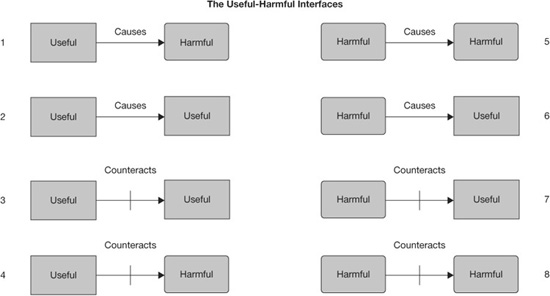
Figure H.3 The two functions can be related in eight different ways
Contradictions are the undesirable situations that fall into four categories. Relationships 1, 3, 6, and 7 in Figure H.3 are all contradictions, as they are two opposite functions connected together. Still, when two opposite functions are connected, they are not necessarily contradictions. Whether a relationship is a contradiction also depends on the time of the connector.
There are three types of contradictions:
• Type 1 is the contradiction that arises when a function produces a similar function but also produces an opposite function. For example, a useful function produces another useful function (desirable) but also produces a harmful function (undesirable). See Figure H.4.
• Type 2 is the contradiction that occurs when a function counteracts an opposite function but also produces another opposite function. For example, a useful function counteracts a harmful function (desirable) but produces a harmful function (undesirable). See Figure H.5.
• Type 3 is the contradiction that results when a function counteracts an opposite function but also counteracts a similar function. For example, a useful function counteracts a harmful function (desirable) but also counteracts another useful function (undesirable). See Figure H.5.
A process without contradictions would be the ideal process, but in reality, there is no such thing as a completely ideal process.
All processes have at least one contradiction. In fact, the reason for analyzing a process is to maximize the useful elements and minimize the harmful elements—in other words, to maximize the real-value-added content while minimizing the non-value-added content of the process.

Figure H.4 A useful function that produces another useful function and a harmful function (Type 1 relationship)
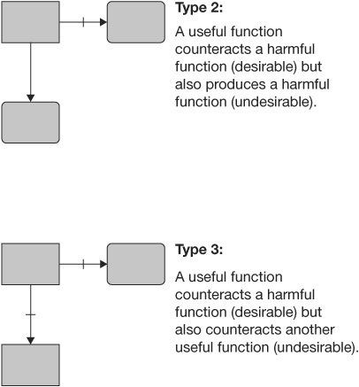
Figure H.5 Example of useful functions that produce Type 2 and Type 3 relationships
Basically there are four ways to resolve contradictions:
• Separation in space. Find a space in which the harmful function doesn’t occur.
• Separation in time. Perform the useful function at a time when the harmful effect doesn’t occur.
• Separation in structure. Find a structural level at which the harmful function doesn’t occur.
• Separate in condition. Find a condition under which the harmful function doesn’t occur.
Let’s look at one of the four options—separation in time. If you were to focus on separation in time, the following things should be considered:
• Separating opposite requirements in time
• Taking preliminary action
• Taking partial preliminary action
• Doing preliminary placement of an object
• Creating and using pauses
• Implementing staggered processing
• Dynamization
• Using post-processing time
• Concentrating energy
• Predestruction
• Reducing strength
• Preliminary stress
• Polysystem with shifted characteristics
• Decreasing stability
• Transitioning from stationary to mobile
• Dividing into mobile parts
• Applying physical effects
• Adding a mobile object
• Using interchangeable objects
• Using elements with dynamic features
• Using adjustable elements and links
To get a better understanding of the harmful and useful functions, let’s consider a lawn mower. The primary function would be to cut grass, which is a useful function. To move that one step lower, think about what are the primary functions that allow it to cut grass. These would include blade rotates, blade has sharp edges, mower has wheels, etc. Each of these is a useful function. For each of these useful functions, we can expand by saying what causes a useful function to operate. For example, blade rotates as a result of an engine that turns the shaft; wheels move based upon a person pushing the lawn mower—each of these is a useful function, and each enlarges on the previous useful function. Continuing with this line of reasoning, what causes the engine to turn? What resources or raw materials are needed? In this case, internal combustion, gasoline, a gas tank, air, air intake, electric spark, spark plugs—each of these is a useful function or factor.
Now let’s change our stream of thought to some of the negative things, for example:
• Turning blades throw objects.
• Turning blades cut feet and hands.
• Engine gives off heat.
• Gasoline costs money.
• Clippings clog motor.
• Motor produces noise.
• Pushing is tiring.
Each of these candidates is a harmful function. When you identify a function, ask yourself if there is any side effect or by-product. For example, the internal combustion side effects are heat, motion, component wear, noise, exhaust, etc. Whenever you identify a harmful function, ask yourself what caused it or what else has to function for it to happen. For example, for internal combustion you need:
• Air
• Kill switch closed
• Spark plugs
• Electricity
All of these could be useful or harmful functions depending on the situation. When you identify a function, ask yourself what inhibits this from happening. For example, for internal combustion we have:
• The ignition switch
• Dirt in gas
• Broken wire
• Water in air
• Clogged blade
We will now look at a problem related to an airplane’s jet engine containment ring.
Figure H.6 is a simple HU diagram of a problem with the fan in a jet engine breaking and causing damage to the airplane. The fan rotates at high speeds (center useful symbol) causing a large quantity of air to move through the engine (useful symbol to the left of center). This is a useful function, as it causes the plane to move. The fan rotating at high speeds causes two detrimental or harmful things to occur—the centrifugal force applies high pressure to the impellers (blades) on the fan, and this high pressure can cause the impellers to burst. The particles from the impellers can damage the airplane. At the same time, the high-speed rotation of the fan gives high energy to the fragments that are flying, which can cause damage to the airplane.
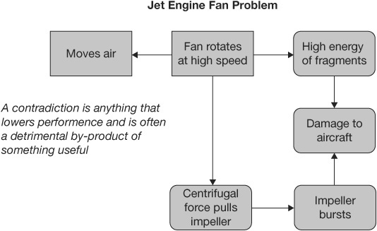
Figure H.6 Starting-point HU diagram of the jet engine problem
Figure H.7 is a more complete HU diagram of the problem of the fan in a jet engine breaking and causing damage to the plane. There are two boxes related to contradictions—fan rotates at high speed and ring is thick. In general, each box in the figure represents an opportunity to address the problem situation. The four circled areas in Figure H.8 indicate the areas that must be addressed first to offset the harmful parts of the diagram and bring into better balance the ratio of harmful and useful functions.

Figure H.7 Detailed HU diagram of a jet engine fan problem
The circled area that includes the useful symbol labeled “Test convenience” and the harmful symbol labeled “Ring is heavy” is an area that presents improvement opportunities to reduce the weight of the containment ring. In this case, the PIT will use an operating principle called uniformity—changing an object’s structure from uniform to nonuniform or changing an external environment (or external influence) from uniform to nonuniform. Using this operator as a starting point, the PIT will adapt it to the conditions set up in the circled area. A typical idea that could come from this analysis would be to change the ring thickness (kind of like a two-liter soft drink bottle) over its length and over its width, making the ring denser and closer in to the blades and directly in line with the blades’ motion but less dense everywhere else.
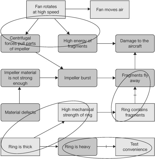
Figure H.8 HU diagram with four areas identified
Another operator principle that could be applied is asymmetry—changing the shape of an object from symmetrical to asymmetrical. This leads the PIT to suggest that the side of the ring closest to the body of the airplane could be thicker to give maximum protection. There would be less damage if the fragments hit the side away from the body of the plane.
The circled area that includes the useful symbol labeled “Ring contains fragments” and the harmful symbol labeled “Fragments fly away” presents another opportunity for improvement. In this case the PIT will use an operating principle called porous material—making an object porous or adding porous elements (inserting insert, coatings, etc.). Using this principle, the PIT could suggest that a honeycomb structure would be more effective. The sharp edges of the structure would act like knives to shred the fragments.
The circled area that includes the harmful symbol labeled “High energy of fragments” and the harmful symbol labeled “Centrifugal forces pull parts of impeller” also presents an opportunity for improvement. In this case, the PIT will focus on reducing the energy of the fragments. To accomplish this, the PIT will use two operating principles—(1) making an object porous or adding porous elements (inserts, coatings, etc.) and composite materials and (2) changing from uniform to a nonuniform composite (multiple) materials. Based upon the use of the concepts in these two operators, the PIT could suggest using multiple lightweight rings. The first ring is thin and stiff but porous. This will shred the blade fragments but doesn’t stop them. The second ring is made from carbon fiber, which is strong and lightweight and stops the fragments.
There is a fourth opportunity available even though it includes two useful symbols. It is the circled area that includes the symbol labeled “Ring is thick” and the useful symbol labeled “High mechanical strength of ring.” In this case, the PIT could use an operating principle called nested doll—in which one object is placed inside another. Using this principle the PIT requires that object, in turn, is placed inside the other. By applying this operator to the situation, the PIT could come up with an idea of using two containment rings, one inside the other. The inside ring could be thicker than the outside one, but put together it will be lighter than one big ring.
The example we used was a design solution, but HU diagrams work equally well for process solutions. Figure H.9 is an HU diagram of the impact of change on an organization. Figure H.10 is an HU diagram of a mass-market problem highlighting two areas where additional actions need to be taken to offset the harmful effects.
Figure H.11 shows how a more in-depth study can be taken related to each of the two target areas using additional submaps of the HU diagram.
Figure H.12 is a typical HU diagram generated by a computer program along with the comments related to key elements on the diagram.

Figure H.9 HU diagram of the impact of change
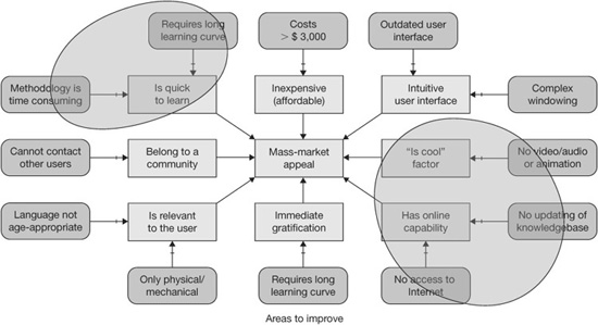
Figure H.10 HU diagram of mass-market problem

Figure H.11 HU diagram of mass-market problem

Figure H.12 Typical HU diagram with comments
Summary
We have found HU diagrams very effective in helping PITs generate highly innovative solutions, in particular when the diagrams are combined with a knowledge-based system like I-TRIZ. The I-TRIZ system contains a world of experience gleaned from problems that have been solved in the past and whose approaches continuously repeat themselves in being useful in solving future problems. It is an effective approach for defining the operator that relates to the problem the PIT is addressing, with practical examples of how to use each of the operators.
I-TRIZ or Operating System for Innovation is a software-supported system sold by 20–20 Innovation and Ideation Inc. It is made up of four software-supported packages. See Figure H.13.
I-TRIZ packages use HU diagrams as their analysis tool. It will construct the HU diagram using its computer program. We suggest that you start with the Inventive Problem Solving software package, although the Directed Evolution software package is a better but more complex methodology. Once the future-state solution is defined, we suggest you use the Failure Prediction software package to define the major risks related to the new process.
