
CHAPTER 20
Hiding the Private Network
In each of the preceding chapters, security planning was presented as a three-level plan that incorporated different types and levels of security devices, techniques, and policies at each level. Internet security is no different. In this setting, the interior is the local user system or the organization’s local area network. Going forward, we will refer to these structures as private networks. In this chapter, you’ll learn to:
- Discuss the advantages and disadvantages of implementing Network Address Translation (NAT) and Port Address Translation (PAT) for network security.
- Define and describe network segmentation and security zones
- Use NAT to create security segments in the network
- Use VLANs to implement security zoning
Understanding Private Networks
After the interior has been secured using the proper devices, techniques, and policies described in the first three chapters, it is necessary to secure the inner perimeter, which is the connectivity points between the individual’s or organization’s private network and the Internet.
The Internet is everything outside your perimeter. The thing is, the Internet is not managed by a single organization, nor is there one organization to secure it for us. Instead, using the Internet means your data is traversing across network devices managed (and maybe secured) by many organizations.
As mentioned earlier, the Internet has customers, employees, and businesses with whom we want to interact more efficiently using the Internet. However, it also has a wide array of different bad people with whom we do not want to interact.
The first security layer to be addressed is the interior. In addition to implementing the devices, techniques, and practices described in the previous chapters, many network security designers also take steps to hide or disguise the private network from the Internet. The following sections will present different techniques and devices that are commonly used for these purposes.
Network Address Translation
Routing is simply the translation of an IP address used in one network to an IP address in another network. Network Address Translation (NAT) is like simple routing, but is when one network is using private addressing, as shown in Figure 20.1. Typically, NAT is used to map a public IP address, such as from the Internet, to an address inside a network.

FIGURE 20.1 NAT Configuration
At the time this translation occurs, the network device performing it (generally, a router or firewall) can also authenticate the request or block it. This mapping may be guided by a NAT table that dictates the specific translation or by using a dynamic scheme that assigns translated IP addresses from an available pool of addresses.
NAT can be performed with policy-based routing (PBR) where the mapping decision is determined by any number of rules, which can be based on many different criteria. These rules are critical to security if outside access to a network is desired.
The Dynamic Host Configuration Protocol (DHCP) is commonly used to define a range of IPs that can be dynamically leased to the requesting system for a preconfigured length of time. The device handling this allocation is called the DHCP server, and it will track all address allocations to avoid allocating the same IP twice. The DHCP server can also support static allocation where an IP address may be reserved for a particular MAC address.
Port Address Translation
An extension to NAT known as Port Address Translation (PAT) supports the concept of mapping multiple or private IPs to a single or public IP address, as described in Figure 20.2. The router assigns a port number that is appended to the IP address, effectively making each address a unique address, even though they share an IP address.

FIGURE 20.2 PAT Configurations
Because IPv4 IP addresses are in such short supply, this concept is currently used almost everywhere. While IP conservation is certainly a main reason for NAT and PAT, these concepts can also help with network security by allowing networks to expose only what is absolutely necessary. Most people think of NAT and PAT as the same thing. Although there is a distinction between these two techniques, the following discussions will treat them this way as well.
Once a connection has been authenticated and all the translation has been done, each packet can be inspected to ensure that the conversation is valid. If an inside client requests something from an outside device, we must know if that packet should be allowed through. Old-school static packet filtering looked only at packet headers, but this technique was easily exploited by an attacker that would indicate in the header that the packet was a reply and would be allowed in.
Modern firewall devices use stateful packet inspection or dynamic packet filtering to analyze the packets further—looking at IP addresses, port numbers, and more. They track this information so they can control their ports, only allowing them to be opened when an internal request asks for it. This practice is used to prevent a common hacking technique known as port scanning. When a hacker knows which ports are in use, they can focus their exploits on the services commonly associated with those ports.
Most home networks rely on NAT as their only security mechanism. While NAT may not be a true security apparatus, it does essentially shut off access to the internal network, unless the administrator deliberately opens outside access and even then, only to a small number of ports. Some would argue this is really enough for a Small Office/Home Office (SOHO) network—and for some it might be. But as hacker tools become increasingly automated, the risk of a SOHO network being the target of an arbitrary attack becomes more and more likely.
While the relative simplicity of NAT offers the home user at least some security and control, a network professional would never rely on NAT as their only defense. If a hacker targets a network, then NAT is nothing more than an obscurity mechanism. Traditional firewall routing will be far easier to troubleshoot and offer a better level of security. Once the world fully transitions to IPv6, it is likely we will hear much less about NAT; but until then, NAT will still have a place in networks to separate public and private IP space.
Many encryption methods will not include port information in the encryption. So, a method known as Network Address Translation-Traversal (NAT-T) was created to get around translation issues encountered on a device using NAT or PAT.
Port Forwarding or Mapping
The strongest feature of NAT/PAT is that by default nothing is translated or forwarded through the device. To move packets through the device, a rule must be explicitly created on the device to forward (or map) the desired protocol port to a private IP address and port in the local area network, as shown in Figure 20.3. This translation process is transparent in that external clients are unaware of the forwarding.

FIGURE 20.3 Port Forwarding
For example, an unusual port mapping could be created that requires web clients to connect using port 4444 instead of the usual port 80. Then, that port could be mapped to port 80 on a private IP in the private network. This might sound like a clever obfuscation, and network administrators do this all the time. However, such a plan really doesn’t provide much security. A hacker can easily port scan the network and learn which ports are open.
Many applications can be configured to use arbitrary ports, allowing many different applications to reside behind a single public IP address. Many of these applications may provide a web interface, but others require specific client software for access. Either way, the client or browser software must be configured to access the public IP address and also provide the external port being mapped.
The port might be in a separate field or appended to the IP address separated by a colon (:). So, for a web browser, this might be something like:
http://203.0.113.86:4444
which might map to 192.168.0.4:8888 on the private network, meaning that on the device using 192.168.0.4, the application being accessed is set up on port 8888.
Port forwarding through Secure Shell (SSH) is known as SSH tunneling. SSH tunneling creates a connection between a remote host and a local device or computer through which services can be relayed. This can be a great way of encrypting protocols that are normally not encrypted. SSH tunneling can be quite complex and can be a way to bypass normal filtering or blocks.
Network Segmentation
Network segmentation, also known as zoning, can be a useful concept for multiple reasons. It is essentially the separation of the network into subnetworks, each of which becomes a segment, as illustrated in Figure 20.4.

FIGURE 20.4 A Segmented Network
Segmenting networks is typically considered when connecting them across different geographical areas, interconnecting different network topologies (such as Ethernet and FDDI), or extending a network that has reached limitations in numbers of nodes or cable length.
While convenience and organizational simplicity can make segmentation a sensible solution, security considerations should drive decisions about network segmentation. From a security perspective, the main reason to deploy network segmentation is to limit the access capabilities of intruders. Each segment will also benefit from reduced congestion and broadcast traffic in addition to containing network problems to a single segment.
These security considerations may also be driven by requirements from outside entities. For example, credit card vendors require that any business that accepts credit cards adhere to the Payment Card Industry Data Security Standard (PCI-DSS). This standard requires the use of firewalls and other security concepts, such as network segmentation, to ensure that all stored credit card information is securely stored both physically and electronically. This requirement even impacts businesses that don’t store credit card data but accept credit cards using a point-of-sale device.
To achieve PCI-DSS compliance, all Point of Sale (POS) terminals and all stored cardholder data must be on a network completely separated from any network area where third parties might have access. Some users may need access to some of the network but certainly not every segment.
Segmentation is critical in the medical field where network administrators must deal with Health Insurance Portability Accountability Act (HIPAA) compliance to ensure the confidentiality of patient medical information.
Access to a network segment is often provided through an access control list, where only users matching some criteria or authentication are allowed access. This is known as a whitelisting. Alternatively, when access is denied only to users matching given criteria this is known as blacklisting. The latter scheme is far less secure, and you should always try to whitelist an ACL rather than blacklist it.
Segmentation can also be used to restrict access between zones by internal users. Sales people may not need to be given access to a server used by the accounting department. However, the accounting staff may need to access sales data on the sales server. These zones need to be connected with each other, but access between zones can be controlled by implementing segmentation.
When allowing outside users into a network, always use the principles of “least privilege” and “need to know” to establish access levels. Give each user the least amount of access possible and only to the areas of the network they must have.
Network segmentation might look to be one of those “set it and forget it” initiatives, but it actually requires continuous management and enforcement. In a large enterprise, segmentation can be a major challenge due to the many different policies and rules involved in such network environments.
We won’t get into the nuances of managing segments and dealing with internal application requirements in this chapter.
As you will see going forward, segmentation is a key component of overall Internet security schemes in many different network environments. If for no other reason, segmentation is so widely employed because of its abilities to minimize the depth of penetration that an intruder might obtain, should they gain entry to the network through the Internet.
Software-Defined Networking
Network virtualization changes the way we must look at network segmentation. A relatively new concept of software-defined networking (SDN) is emerging that essentially analyzes the connection between any two nodes and can filter that connection based on a defined policy. This micro-segmentation will make security more powerful when it is widespread but will certainly make certain management aspects more complex.
Network Virtualization
Computer platforms have evolved enough that we can simulate hardware platforms such as servers, routers, and most any other network resource using software. Through software, a single piece of hardware can support multiple virtual instances, as shown in Figure 20.5. Each instance has the ability to function like the original host hardware. Virtual instances can be enabled as needed to handle demand and scalability, or to provide tremendous amounts of portability.

FIGURE 20.5 Virtual Instances
Network virtualization is also a way to segment your network by creating overlay networks, (essentially a network built on top of another, physical or underlay, network). It is possible to use white box switches (generic routing and switching hardware) in these overlay networks.
Network virtualization can provide a virtual network completely separate from other network resources, creating a zone just as you would with traditional network hardware. Network virtualization can also be used to implement software-driven virtual network storage units. This is seen in storage area network (SAN) deployments.
VLANs
A VLAN, or virtual LAN, is simply a software-configured network where hosts will behave as if they are all connected to the same physical network even when they are not. This allows several networks or broadcast domains to work, virtually, as a single LAN and broadcast domain, as shown in Figure 20.6. This reduces latency and can often make network segmentation much simpler to understand and maintain. However, you now have to deal with additional security issues such as the spread of viruses and malware across your new logical network rather than within a single physical network.
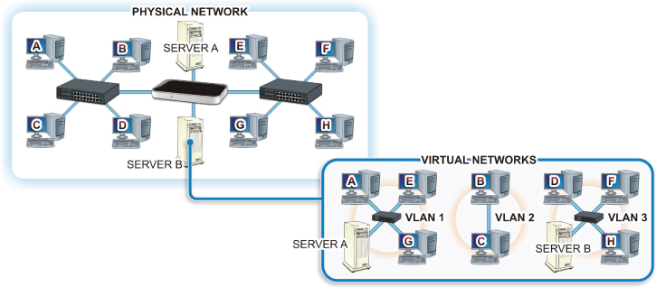
FIGURE 20.6 A VLAN
VLANs are typically set up on a router or a switch; but to pass traffic from one VLAN to another, you must have hardware that will support VLANs or VLAN tagging. VLANs can be port-based or tagged/untagged. The Ethernet frame header contains a VLAN ID and part of this is the Tag Protocol Identifier (TPID).
If a packet contains VLAN information, then it is considered a tagged packet or an untagged packet if it does not. A port-based VLAN could simply be a group of ports on an Ethernet switch that form a segment, or it could span multiple switches.
A managed Layer 2 switch may be configured to forward or block traffic to or from specific VLANs and can add the VLAN tag to the header or encapsulate the frame within another type of transmission frame if you are exchanging data with different network technology. The switch might even support trunk lines between switches, and a trunk port will carry all of the traffic accessible by that switch. A Layer 3 switch (or a router) supporting VLAN tagging can support all of the routing and blocking of data between VLANs as well.
Hands-On Exercises
Objectives
- Check system for compatibility with Hyper V.
- Enable Hyper V on a Windows 10 Professional computer.
- Install and explore a virtual switch Hyper-V Manager.
- Install a virtual machine.
Resources
- Customer-supplied desktop/laptop hardware system
- Windows 10 Professional installed (Home edition cannot run Hyper-V)
- A downloaded Linux distribution to install
- An account with administrative privileges
Discussion
Computer platforms have evolved enough that we can simulate hardware platforms such as servers, routers, and most any other network resource using software. Through software, a single piece of hardware can support multiple virtual instances. Each instance has the ability to function like the original host hardware. Virtual instances can be enabled as needed to handle demand and scalability, or to provide tremendous amounts of portability.
Network virtualization is also a way to segment your network by creating overlay networks (essentially a network built on top of another, physical or underlay, network). It is possible to use white box switches (generic routing and switching hardware) in these overlay networks.
Procedure
In this procedure, you will learn how to enable virtualization technology, configure a virtual switch, and install a virtual machine (VM) on your Windows 10 Professional computer.
Checking Hyper-V Compatibility
Check your Windows 10 Professional computer for compatibility with Hyper-V.
- Turn on your computer.
- Log on using your account with administrative privileges.
- On your desktop in the embedded search bar on your taskbar, type cmd and press Enter to open the Command Prompt window.
- In the Command Prompt window, type systeminfo.exe and press Enter.
- After a few moments, your system information should be listed in the Command Prompt window, as shown in Figure 20.7.
FIGURE 20.7 Systeminfo Command Output
- Under Hyper-V Requirements, if the results indicate Yes, you may enable Hyper-V without any further steps. If the results read No, you may need to go into your BIOS to enable hardware features or your hardware may be incompatible with Hyper-V.
Enabling Hyper-V in Windows 10 Professional
Once the compatibility verification has been completed and any required adjustments have been made in the BIOS, proceed with the following steps to enable Hyper-V on your Windows 10 Professional computer.
- If you have not done so already, boot your computer and log on using an account with administrative privileges.
- On your desktop in the search bar embedded in your taskbar type turn windows features on or off and press Enter.
- The Windows Features window should appear, and it should look similar to the one displayed in Figure 20.8.

FIGURE 20.8 Windows Features
- Locate and click the box next to Hyper-V to tell Windows to turn on this feature, as shown in Figure 20.9.

FIGURE 20.9 Enabling Hyper-V
- Click OK.
- Windows will process the change and provide a prompt indicating that you need to reboot to finish installing the requested feature, as shown in Figure 20.10. Click the Restart Now button.

FIGURE 20.10 Ready for the Reboot
Congratulations on enabling virtualization technology on your computer.
Pinning Hyper-V Manager to Your Taskbar
- If you have not already done so, log on to your computer using your account with administrative privileges.
- In your search bar, type Hyper-V Manager.
- In the menu options presented, right-click on Hyper-V Manager and choose Pin To Taskbar, as shown in Figure 20.11.

FIGURE 20.11 Pinning Hyper-V to Taskbar
- Click the Hyper-V Manager icon now pinned to your taskbar to open it.
Installing and Configuring a Virtual Switch
You should take time to explore the many options and configuration features of the Hyper-V Manager at your leisure, However, for this exercise, we will move right into the configuration of a virtual switch to be used with the installation of a virtual machine.
- In the right Actions pane of the Hyper-V Manager window, click Virtual Switch Manager.
A new window titled “Virtual Switch Manager for ‘Your Computer’s Name’” should appear, as shown in Figure 20.12.

FIGURE 20.12 Virtual Switch Manager
- A virtual switch is installed by default and is associated with your active NIC. But let’s examine the options provided when setting up a switch for use with your VMs.
- If it is not already selected, click New Virtual Network Switch, under Switches in the left pane of the window.
When creating a virtual switch, you should be presented with three options:
- External: Creates a virtual switch that binds to the physical network adapter so that virtual machines can access a physical network.
- Internal: Creates a virtual switch that can be used only by the virtual machines that run on this physical computer, and between virtual machines and the physical computer. This does not provide connectivity to a physical network connection.
- Private: Creates a virtual switch that can be used only by the virtual machines that run on this physical computer.
- Highlight External and click on the Create Virtual Switch button. This should bring you to a new set of options
How To Configure Your Virtual Switch.
- In the Name field, type Test Switch.
- Under Connection type, make sure the radio button next to External is selected.
- If you have multiple NICs in your computer, you may select whichever NIC you use to connect to the Internet, but this should have been selected by the Switch Manager by default.
- Verify the box next to Allow Management Operating System To Share This Network Adapter is checked. If it is not, then click on it to place a check in the box.
- Click the Apply button at the bottom of this window. This will bring up a warning, as shown in Figure 20.13. Click the Yes button.
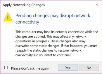
FIGURE 20.13 Apply Network Changes Warning
- At the bottom of the Virtual Switch Manager window, click the OK button. This should take you back to the Hyper-V Manager window.
Installing a Linux Distribution in Hyper-V
- Download an Ubuntu distribution and save it to a location where you can find it. For this example, we are using Ubuntu 16.04.3.
- If Hyper-V is not open, click on the Hyper-V Manager icon on the taskbar to open it.
- In the right-hand pane under Actions, locate and click New. This should present a side menu to create a new virtual machine, hard disk, or floppy disk.
- Click on Virtual Machine to bring up the New Virtual Machine Wizard, as shown in Figure 20.14.

FIGURE 20.14 New Virtual Machine Wizard – Before You Begin Window
- Click Next. This should take you to the Specify Name And Location window, as shown in Figure 20.15.

FIGURE 20.15 Specify Name and Location
- Enter Test Linux in the Name field and click Next.
- You should be at the Specify Generation window. Leave the Default Generation 1 radio button selected and click Next.
- The Assign Memory window should appear. Again, for the purposes of this lab, leave the default assignment and click Next.
- The Configure Networking window should appear. In this window, the default setting is Not Connected. Click on the drop-down menu and select the Test Switch we previously created, as shown in Figure 20.16.

FIGURE 20.16 Selecting the Network Connection
- The Connect Virtual Hard Disk window should appear. In this window, you will select whether to create a virtual HD, use an existing Virtual HD, or attach a virtual HD later. For this exercise, leave the default values and click Next.
- At the installation option, click the radio button next to Install An Operating system From A Bootable CD/DVD-ROM.
- Click the radio button next to Image File (
.iso) and click the Browse button next to the File Location field. - Browse to the location of your downloaded Linux ISO, click on the file to select it, and then click the Open button, as shown in Figure 20.17.

FIGURE 20.17 Selecting the ISO
- The
.isofile path should be populating the Image File field. Click Next. - This brings you to a Summary page showing the settings you have selected for your installation. Click Finish to complete the installation of the virtual machine.
- Your new Linux virtual machine should now appear in your Hyper-V Manager, as shown in Figure 20.18.

FIGURE 20.18 Virtual Machine Installed in Hyper-V
- You will still need to install the OS from your image file onto this virtual machine to make it usable, but you have now enabled and applied a virtual machine to your Windows 10 computer.
If you power on your virtual machine, you will be prompted to install your Linux distribution on the virtual machine. Upon completion, it should look like Figure 20.19.
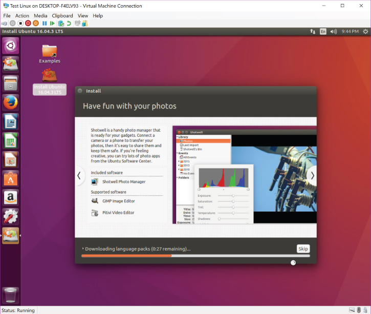
FIGURE 20.19 Ubuntu Linux 16.04.3 LTS Running as a VM
You may also use Hyper-V Manager to import and export existing virtual machines. This is useful in terms of saving an uncorrupted backup of your existing virtual machine installations, as well as troubleshooting issues on existing VMs within your enterprise structure.
Lab Questions
- What command prompt utility program is used to verify a Windows computer’s compatibility with Hyper Visor?
- As there is no installation file for Hyper Visor on Windows 10 Professional, where do you go to enable Hyper-V in this operating system?
- What three configuration options are available when you’re creating a virtual switch in Hyper-V?
- Once a virtual machine has been created, can you change its generation?
Lab Answers
- What command prompt utility program is used to verify a Windows computer’s compatibility with Hyper Visor?
systeminfo.exe - As there is no installation file for Hyper Visor on Windows 10 Professional, where do you go to enable Hyper-V in this operating system?
Turn Windows features on or off.
- What three configuration options are available when you’re creating a virtual switch in Hyper-V?
External, Internal, and Private.
- Once a virtual machine has been created, can you change its generation?
No.