
CHAPTER 12
Networking Basics
When only two intelligent devices are connected, simple direct connections can be made using cables, light signals, or radio waves. The interconnected devices only need to speak the same digital language and use an agreed-upon communication control method to manage the flow of information between them. However, when more than two intelligent digital devices are linked together, a network is formed. When a third device is added to the system, additional control methods must be put into place to not only control the conversations between the devices, but to make sure the correct parties on the network receive the information and that information not intended for other parties is kept private. In this chapter, you’ll learn to:
- Identify the characteristics of common network types
- Describe the primary function of the different layers of the OSI networking model
- Discuss how the layers of the OSI model correspond to the generation of network data transmission packets
- Explain how different OSI model layers apply to cybersecurity issues
- Describe standard networking topologies
Understanding the Basics of Networking
In the Information Technology (IT) world, there are two basic types of networks:
- Networks that exist in a relatively confined geographical area are referred to as local area networks (LANs).
- Networks distributed over wider geographical areas are referred to as wide area networks (WANs).
There are several less-well-defined versions of these basic area network types, as described in this section.
In all of the following network types, two fundamental considerations must be in place to implement communications between the network’s devices: its physical or logical connection method (topology) and the rules governing its communication processes (or protocols). You must be able to link the network components together, and they must all use the same signal types and language.
Campus Area Networks or Corporate Area Networks (CANs)
Campus area networks or corporate area networks (CANs) are combinations of interconnected local area networks inside a limited geographical area.
Metropolitan Area Networks (MANs)
Metropolitan area networks (MANs) are widespread combinations of interconnected local area networks inside a medium-sized geographical area. This designation is applied to networks that operate between LANs and WANs and most likely connect different LANs to a WAN.
Wireless Local Area Networks (WLANs)
Wireless local area networks (WLANs) are local area networks of more than two devices that are connected by wireless radio communication methods. These networks may also interconnect through a wireless access point, which also attaches the LAN to a wide area network, such as the Internet.
Storage Area Networks (SANs)
Storage area networks (SANs) are a network of dedicated storage devices configured for the express purpose of providing consolidated data storage. These devices act in a transparent manner so that they appear to be an integral part of the network’s server(s).
The OSI Networking Model
Networks are complex, multifaceted structures that require a tremendous amount of interaction between computer designers, network equipment designers, operating system manufacturers, and networking application providers. Several initiatives have been put forward to provide models to serve as blueprints for these groups to follow in designing their products. While you should be aware that different hierarchical networking models exist, the most widely discussed initiative is the open systems interconnection (OSI) model put forward by the International Standards Organization.
The OSI model helps us conceptualize how data is handled between two networked systems. To do so, the OSI model divides the working flow of data into abstract layers. Although the layers are not literal in any sense, nor do they provide any actual barrier for product design, the layers do help people respect and understand the flow of how data gets managed.
The layers of the OSI model are shown in Figure 12.1. In the figure, each layer on the left is matched with a group of protocols that operate within it on the right. As you can see, many protocols are at work in network architectures.
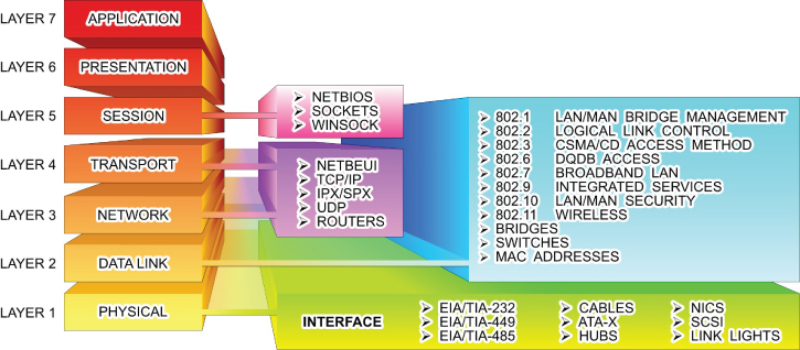
FIGURE 12.1 The OSI Networking Model
The primary functions of the layers are summarized in the following sections.
Layer 1: Physical
This layer is concerned with the transmission media used to move data. Functions associated with this layer include moving the data onto the transmission media, providing electrical or light signals, the mechanical compatibility between the communications port and the media, and activation and deactivation of the physical connection.
Layer 2: Data Link
This layer involves controlling how the data is packaged and moved between communication points. At this layer, the data is formatted into frames suited for transmission. Components at this level also add error detection and correction functions to the frames, as well as media access protocols and specific information about transmission to specific nodes on the same network segment.
Layer 3: Network
Elements of the network layer are responsible for controlling the routing of data packets between different communication nodes, network segments, or media types. This includes multiplexing and demultiplexing signals as they pass from one media type to another, assembling and disassembling message packets, and establishing, maintaining, and terminating connections.
Layer 4: Transport
The transport-level components are responsible for providing an orderly end-to-end flow of data that includes sequencing of data packets and providing basic error-recovery functions and flow control.
Layer 5: Session
This layer of the model is dedicated to setting up and managing sessions between applications as well as providing parameters such as security. Activities conducted by components at this level include stopping and starting data transfers, controlling the flow of data between applications, and providing network failure recovery options. This layer deals with management of transmission security options such as authentication and tunneling protocols.
Layer 6: Presentation
The elements of this level are tasked with controlling how the data looks to the user at the destination end. Functions provided by components at this level include visually formatting and presenting data, dealing with data compression and encryption functions, and starting/stopping control of sessions.
Layer 7: Application
The highest level of abstraction for the OSI model is concerned with the network handling of data for end-user applications. Services such as email and the web browser are application examples where the application layer is functioning. At this level of the model, user IDs and passwords are authenticated and user services are provided.
Data Transmission Packets
When data is moved from one communication node to another, the elements associated with each level of the OSI model add a header to the message that contains the information necessary to carry out the transfer. Technically, at some OSI layers, a small footer is also added to create an envelope. But for the sake of discussion, we’ll focus on the headers. The data could be digitized text, numbers, voice, video, or any other type of digitized information. When the command is given to move the data at the sending node (for example, by pressing Send on an email message), the packeting process progresses as described in Figure 12.2.

FIGURE 12.2 Building Transmission Packets
As the data packet leaves the application, an additional header (block of information) is added to the message as it moves through the different OSI layers on its way to the transmission media. On the receiving end, the entire message is brought into the designated receiving node, where each layer’s header is examined, the appropriate header removed, and the message acted on by its corresponding layer.
The steps involved in the communication process are typically carried out without any intervention from the user who is sending the message. The different headers and activities are functions of the application, the physical network adapter, and all the “layers” in between.
OSI Layer Security
Every networking course examines the OSI model in terms of which types of devices, protocols, and functions exist at each level. However, different cybersecurity challenges may be present at each level. Table 12.1 lists the security focus related to each layer.
TABLE 12.1 OSI Layer Security
| OSI LAYER | Network Security Model | Exploit Type | Security Focus |
| 1) Physical Layer | 7) Physical Level | Physical Tampering/Break-in | Physical Security |
| 2) Data Link Layer | 6) VLAN Level | Network Scanning Local/Internal | Access Security |
| 3) Network Layer | 5) ACL Level | Network Scanning Complete/Internal | Domain Security |
| 4) Transport Layer | 4) Software Level | Software Specific Exploits | Port Security |
| 5) Session Layer | 3) User Level | Social Engineering – Users | Authentication/Encryption |
| 6) Presentation Layer | 2) Administrative Level | Social Engineering – Administrators | Authentication |
| 7) Application Layer | 1) IT Department Level | Social Engineering – IT Staff | ID/Authentication |
You can also apply the three-layered rings of security developed in the previous chapters to the layers of the OSI model. As a matter of fact, the three-layer ring actually exists in two places—the transmitting device and the receiving device. Therefore, the outer perimeter is established at the physical termination or connection point of each device. The cable or airwaves between the devices connect their outer perimeters.
The outer perimeter corresponds to the Layer 1 components of the OSI model. Securing the physical layer in a network involves securing the physical media, as well as the networking and communication equipment.
Likewise, the inner perimeter is associated with the Layer 2 components of the model. The components working at this level represent the first layer of logical defense. At this level data can be accepted, discarded, or forwarded based on its identity.
Finally, the interior ring can be viewed as including Layer 3 through Layer 7. Each of these layers provides options for preventing unauthorized movement to a higher level. For example, port-blocking mechanisms associated with firewalls work at Layer 4.
However, the Layer 7 components represent the most desired targets of a cyber attack. Attacks aimed at this level are designed to gain control of physical assets or compromise the operation of software applications.
Throughout Part III, you will learn about the operation of different network components, their positions in the OSI architecture, and their related security vulnerabilities and remedies.
Network Topologies
Network topologies are Layer 1 physical (or logical) connection strategies that fall into four basic configurations, as illustrated in Figure 12.3.

FIGURE 12.3 Bus, Ring, Star, and Mesh Configurations
- Bus
- Ring
- Star
- Mesh
In the bus topology, the nodes, or stations, of the network connect to a central communication link. Each node has a unique address along the bus that differentiates it from the other users on the network. Information can be placed on the bus by any node. The information must contain the network address of the node, or nodes, for which the information is intended. Other nodes connected to the bus will ignore the information. In a ring network configuration, the communication bus is formed into a closed loop. Each node inspects the information on the network as it passes by. A repeater, built into each the network adapter of each node, will regenerate every message not directed to it and send it to the next appointed node. The originating node eventually receives the message back and removes it from the ring. Ring topologies tend to offer very high data-transfer rates but require additional management overhead. The additional management is required for dependability. If a node in a ring network fails, the entire network fails. To overcome this, ring designers have developed rings with primary and secondary data paths as depicted in Figure 12.4. If a break occurs in a primary link, the network controller can reroute the data onto the secondary link to avoid the break. FIGURE 12.4 Primary/Secondary Ring Topologies In a star topology, the logical layout of the network resembles the branches of a tree. All the nodes are connected in branches that eventually lead back to a central unit. Nodes communicate with each other through the central unit. The central station coordinates the network’s activity by polling the nodes, one by one, to determine whether they have any information to transfer. If so, the central station gives that node a predetermined slice of time to transmit. If the message takes longer to transmit than the time allotted, the message will be chopped into small packets of information that are transmitted over several polling cycles. The mesh network design offers the most basic network connection scheme and the most extensive management scheme. In this topology, each node has a direct physical connection to all the other nodes in the network. Mesh topologies are employed in two very large network environments—the public telephone system and the Internet, as well as in small, wireless piconet communication networks that include Bluetooth and ZigBee networks. Piconets are small, short-range networks of devices grouped together to communicate on the same channel. One of the devices operates at the master device, or coordinator, while the other devices operate as slaves. The role of master device can circulate through the network with different devices assuming that role as it becomes available.Bus Topology
Ring Topology

Star Topology
Mesh Topology
Logical Topologies
It would be easy to visualize the connections of the physical topologies just described if the nodes simply connected to each other. However, this is typically not the case in most network arrangements. This is due to the fact that most networks employ connectivity devices, such as hubs, switches, and routers, which alter the appearance of the actual connection scheme. Therefore, the logical topology will not match the appearance of the physical topology—the particulars of the connection scheme are hidden inside the connecting device.
As an illustration, Figure 12.5 shows a typical network connection scheme using a connecting device to consolidate connections in a single location. The physical topology appears as a star. However, the internal wiring of the connecting router provides a logical bus topology. It is not uncommon for a logical ring or mesh topology to be implemented in a physical star topology.

FIGURE 12.5 Logical Topologies
Hands-On Exercises
Objectives
- Describe the purpose of IPsec.
- Create a Connection Security rule.
- Explore the options of creating a Connection Security rule.
- Define “integrity and confidentiality” as they apply to IPsec.
Resources
- Customer-supplied desktop/laptop hardware system
- Windows 10 Professional installed (This procedure will also work successfully on PCs running Windows 10 Home Edition.)
- An account with administrative privileges
Discussion
Internet Protocol Security (IPsec) is an open standard using a suite of protocols for encrypting and authenticating IP communication that is commonly used in VPNs.
Protocols in this suite include:
- Authentication Headers (AH) provide data integrity and origin authentication to protect against replay attacks (attacks where a recorded transmission is replayed by an attacker to gain access). Encapsulating Security Payloads (ESP) offers origin authentication as well as encryption. ESP encrypts and encapsulates the entire TCP/UDP datagram within an ESP header that does not include any port information. This means that ESP won’t be able to pass through any device using port address translation (PAT).
- Security Associations (SAs) offer a number of algorithms and frameworks for authentication and key exchange.
- Internet Key Exchange (IKE) is the protocol used to set up a security association in IPsec.
Unlike SSL, IPsec operates at Layer 3 in the OSI model and secures everything in a network. IPsec also differs from SSL in that it is implemented on a client system, whereas SSL is built into a browser. All of this combined leads to a safer environment for transferring data, usually at a faster rate. There are two modes of IPsec:
- Transport mode – The IP payload is encapsulated only.
- Tunnel mode – The entire IP packet is encapsulated.
Connection Security includes authenticating two computers prior to communication and then ensuring the confidentiality between them. Windows employs IPsec to achieve Connection Security.
Procedure
In this procedure, you will discover how and where IPsec is configured. You will create a new Connection Security rule, and explore the options associated with IPsec. This procedure is intended to instruct you on how to create an IPsec communication; however, you will not be able to test it in this environment.
Accessing IPsec
IPsec is located within Windows Firewall with Advanced Security. It has been renamed Connection Security; however, it is generally stated that Connection Security is achieved by using IPsec rules.
- Power on your machine.
- Log on to Windows using your administrative account.
- At your desktop, in the search bar embedded in your taskbar, type wf.msc and press Enter.
- This should launch the Windows Firewall with Advanced Security.
- Click the Connection Security Rules entry, as illustrated in Figure 12.6. The middle pane should have no current rules established.

FIGURE 12.6 Windows Firewall with Advanced Security
- Expand Monitoring and then Security Associations by selecting the arrow next to each, as illustrated in Figure 12.7.

FIGURE 12.7 Expanded Monitoring and Security Associations Items
Creating a New Connection Security Rule
- Right-click Connection Security Rules in the left pane and select New Rule to launch the New Connection Security Rule Wizard, as shown in Figure 12.8.
FIGURE 12.8 New Connection Security Rule Wizard
Depending on the Rule Type selected, there are anywhere from four to seven steps. Each step has multiple options from which to choose.
- Record the Rule Types in Table 12.2. Pay special attention to the definitions of each.
TABLE 12.2 Rule Types
Isolation
Authentication exemption
Server-to-server
Tunnel
Custom
- Select each radio button next to the Rule Types to explore the different steps necessary for each. When finished, select the radio button associated with Isolation.
The Rule Type specifies some basic settings based on the intended use of the rule. The Isolation rule will restrict access based on the authentication type and the network profile.
- Click the Next button to proceed to the Requirements window.
The choices here include:
- Request authentication, but do not require.
- Require authentication for inbound and outbound.
- Require inbound, request outbound. A hybrid of the previous two options.
- Read the definition of each and select Request Authentication For Inbound And Outbound Connections, as illustrated in Figure 12.9.

FIGURE 12.9 New Connection Security Rule Wizard – Requirements Window
- Click Next to view the Authentication Method window.
Although four options are listed, the two involving Kerberos V5 are restricted to connections made within an Active Directory forest.
- Select the radio button next to Advanced to make the Customize button available, as shown in Figure 12.10.

FIGURE 12.10 The Customize button is active.
- Click the Customize button to launch a separate Customize Advanced Authentication Methods window, as shown in Figure 12.11.

FIGURE 12.11 Customize Advanced Authentication Methods Window
In this window, you can customize a list of authentication methods to fit your needs. Explore the window carefully.
- Click the Add button located under First Authentication Methods: The Add First Authentication Method window will appear, as shown in Figure 12.12.
FIGURE 12.12 Add First Authentication Method Window
This Add First Authentication Method window offers four possible authentication methods from which to choose:
- Kerberos V5
- NTLMv2
- Certificate
- Preshared key (not recommended)
- After exploring the options, click Cancel to exit the window. Click Cancel in the Customize Advanced Authentication Methods window as well.
- You should be returned to the New Connection Security Rule Wizard – Authentication Method window. Select the radio button next to Default and then click Next. You will be directed to the Profile window.
These selections relate to the network connections in place on the computer. While a standalone computer in a networked office may not need to worry about using a Public network, a traveling laptop will need to ensure integrity and confidentiality over the Internet.
- Leave all three check boxes selected, as shown in Figure 12.13, and click Next to move to the Name window.

FIGURE 12.13 New Connection Security Rule Wizard – Profile Window
- Enter Request IPsec Rule under Name. Leave the Description (Optional): blank, as shown in Figure 12.14.

FIGURE 12.14 Naming the Rule
- Click Finish to save the rule. You are brought back to the Windows Firewall With Advanced Security window. The new rule is now located in the middle pane, as illustrated in Figure 12.15.

FIGURE 12.15 Viewing the New Rule
Notice the right pane. The Actions panel has changed and more options are available.
To create an IPsec connection, another computer would configure a Connection Security rule using the same process. Any time the computers want to transfer information, an IPsec connection needs to be completed.
Recall that you selected the Request Authentication, Not Required option. Therefore, you can still connect to anyone else without a secure connection.
- Select the rule in the middle pane to highlight it. In the right pane, click the Properties entry, as shown in Figure 12.16.
FIGURE 12.16 Request IPsec Rule Properties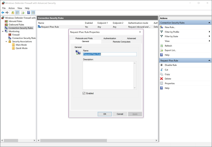
Each tab allows you to adjust the settings you selected in the New Connection Security Rule Wizard.
- Explore each tab, and then click the Cancel button to exit the Properties window.
Monitoring IPsec Connections
Under the Monitoring directory, you can view any active rules being used for IPsec. Although you will not see any active rules, it is important to know where to view this information and what it means.
- If the Monitoring directory and the Security Associations directory in the left pane are not expanded, expand them now by selecting the arrows next to them.
- Select Main Mode in the left pane. Nothing should be listed in the middle pane.
Main mode is phase 1 on the IPsec connection. It uses cleartext to establish how it will proceed.
- Select Quick Mode in the left pane. Again, nothing should be listed in the middle pane.
In Quick mode, which is considered to be Phase 2, communication parameters are negotiated.
If a connection were active, you would be able to see each listed with the applicable AH and ESP protocols in place. AH gives integrity, while ESP provides both integrity and confidentiality.
- Integrity – Confirming that the data packets have not been tampered with. Prevents man-in-the-middle attacks.
- Confidentiality – Confirming that the data packets cannot be viewed by a malicious user. Prevents network sniffers from viewing data.
Lab Questions
- What protocols are used in the IPsec standard?
- At which level of the OSI model does IPsec operate?
- With regard to authentication, what are the three options for Requirements?
- Describe the difference between “integrity” and “confidentiality” as it relates to IPsec.
- Define Connection Security.
Lab Answers
- The protocols in this suite include:
- Authentication Headers (AH) provide data integrity and origin authentication to protect against replay attacks (attacks where a recorded transmission is replayed by an attacker to gain access).
- Encapsulating Security Payloads (ESP) offers origin authentication as well as encryption. ESP encrypts and encapsulates the entire TCP/UDP datagram within an ESP header that does not include any port information. This means that ESP won’t be able to pass through any device using port address translation (PAT).
- Security Associations (SAs) offer a number of algorithms and frameworks for authentication and key exchange.
- Internet Key Exchange (IKE) is the protocol used to set up a security association in IPsec.
- Unlike SSL, IPsec operates at Layer 3 in the OSI model and secures everything in a network. IPsec also differs from SSL in that it is implemented on a client system, whereas SSL is built into a browser.
- All of this combined leads to a safer environment for transferring data—usually at a faster rate. The options include:
- Request authentication, but do not require.
- Require authentication for inbound and outbound.
- Require inbound, request outbound. A hybrid of the previous options.
- The IPsec standard uses a suite of protocols to accomplish its goal of securing data. AH gives integrity while ESP provides both integrity and confidentiality.
- Integrity – Confirms that the data packets have not been tampered with. Prevents man-in-the-middle attacks.
- Confidentiality – Confirms that the data packets cannot be viewed by a malicious user.
- Prevents network sniffers from viewing data.
- Connection Security authenticates two computers prior to communication and then ensures the confidentiality between them. Windows employs IPsec to achieve connection security.