Chapter 5
5G Fundamentals
Perhaps very few market segments have gone through the type of market adoption seen in the mobile industry. 5G does not start the mobility revolution from scratch but rather builds on the concepts and innovations of previous generations. For instance, near-real-time services have already been available in 4G, enabling real-time gaming and augmented reality applications for leisure. 5G is expected to push this further with enhanced reliability and low-latency capabilities for applications such as industrial automation, self-driving vehicles, remote medical care, and other mission-critical applications.
Similarly, mobile bandwidth has already been steadily growing to allow live video or video-on-demand over LTE, as well as multipoint videoconferencing. 5G aims to enable enhanced mobile broadband for everyone.
The fundamentals covered thus far in the previous chapters lay the foundation for the generational leap to 5G. This chapter brings those fundamentals together and dives deeper into the innovations that shape 5G. This chapter continues to focus on three domains of the mobile communication network—RAN, mobile core, and transport—and explores how each of these evolves to create a complete 5G experience.
5G Radio Access Network
Among the many parts comprising a fifth-generation mobile network, not many are entirely novel. Undeniably, significant innovations distinguish 5G radio technology from its predecessors, but all of these essential innovations are deeply rooted in technologies developed for previous generations of networks. After all, LTE proved its ambitious name by giving a solid foundation for mobile radio network evolution in the long term. Proper understanding of these innovations is fundamental for 5G mobile core network (MCN) capacity planning, architectural definitions, as well as technology selection.
Air Interface Enhancement
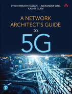
The radio access technology of 5G networks is called 5G New Radio (5G NR), or NR for short. Although it is based on the same Orthogonal Frequency-Division Multiple Access (OFDMA) technology, a few important innovations distinguish it from LTE radio access. Unlike LTE with its fixed subcarrier spacing in Orthogonal Frequency Division Multiplexing (OFDM), NR supports multiple spacings with wider subcarriers. In addition to 15 KHz, NR also supports OFDM subcarrier widths of 30, 60, 120, and 240 KHz.1 The radio frame of NR has the same duration of 10ms as in LTE and is divided into 10 subframes. However, the similarities in the frame structure between LTE and NR end here, and further subdivision of an NR subframe differs significantly from that of LTE. There are two slots per subframe in LTE, with each normally carrying seven OFDM symbols (or six in some cases). In contrast to that, 5G NR slots carry 14 OFDM symbols.
Subcarrier width and OFDM symbol duration are inversely proportional; therefore, the use of wider subcarriers effectively reduces the duration of an OFDM symbol. With a fixed number of OFDM symbols per slot, a 1ms NR subframe can have anything from one slot (with 15 KHz subcarrier spacing) to 16 slots (with 240 KHz spacing).2 The use of wider subcarrier spacing and shorter slots decreases radio interface latency, thereby benefiting URLLC scenarios. Figure 5-1 illustrates the difference in NR framing structure depending on subcarrier spacing.
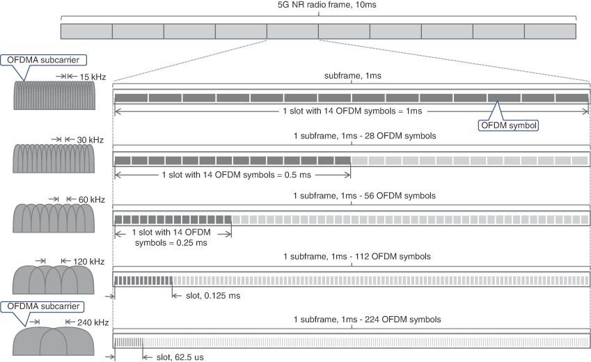
FIGURE 5-1 5G NR Frames, Slots, and OFDMA Subcarriers
In both LTE and NR, slots are used to schedule data over the radio interface, but NR can schedule data in a more efficient way. Besides using more diverse slot durations, 5G NR offers flexible use of individual symbols within a slot. Contrary to LTE, the use of slots and OFDM symbols within each slot is not rigidly prescribed by the 5G specification. The control information, data, and receipt acknowledgment can be sent within a single slot, significantly reducing latency in the network and allowing faster retransmissions of lost data.
Just like in previous generations, both FDD and TDD duplexing methods can be used in NR. When FDD duplexing is used, all the slots in the frame are used for either downlink or uplink communication in their respective bands. On the other hand, a frame in TDD duplexing may contain slots for both downlink and uplink communications. The TDD concept is taken even further in NR, with each individual OFDM symbol being used for downlink or uplink communication within a single slot. There are a number of different formats for uplink, downlink, and flexible (either down or uplink) symbols in a slot defined in the 3GPP 5G; NR; Physical layer procedures for control specification.3 As a result, the receiver does not have to wait for the beginning of a new slot to start receiving data after control information, and then for another slot to send an acknowledgment back. Everything can be done within a single slot, provided the chunk of data is short enough. Such a slot is said to be self-contained, as it has all necessary information to decode and use the data it delivers. This helps not only TDD but FDD as well, as all necessary information is delivered in a self-contained slot.
To improve latency characteristics of NR for ultra- and very-low-latency scenarios even further, 3GPP’s Study on new radio access technology proposes the use of a mini-slot with a smaller number of OFDM symbols.4 A mini-slot can have as few as only one OFDM symbol and can be scheduled immediately, without waiting for the beginning of a new regular slot. In some cases, mini-slots can preempt data already scheduled for transmission via a process called puncturing, reducing latency for URLLC use cases even further.
5G NR Channel Widths and Carrier Aggregation
To boost the peak rates and overall cell capacity, 3GPP defined wider channels for 5G NR, ranging from 5 MHz to as wide as 400 MHz, depending on the frequency range used. For sub-7 GHz bands, also known as Frequency Range 1 (FR1), channel widths can be between 5 MHz and 100 MHz.5 Channel widths of 50 MHz through 400 MHz are specified for the bands above 24 GHz, known as Frequency Range 2 (FR2).6
Not every combination of subcarrier spacing and channel width is supported by 3GPP specifications. For example, 15 KHz subcarrier spacing can be used in channels 5–50 MHz wide but is not supported with wider channels. Moreover, subcarrier spacings of 15 KHz and 30 KHz are not supported in FR2 at all, due to significantly different propagation characteristics of mmWave, as was mentioned in Chapter 2, “Anatomy of Mobile Communication Networks.” Subcarrier spacings of 15 KHz and 30 KHz, with their longer OFDM symbol duration, are effective in combating inter-symbol interference in macrocells covering large areas but would make transceivers unnecessarily complex and expensive in mmWave bands. A comprehensive list of supported subcarrier spacings and channel widths is defined in 3GPP’s “5G; NR; User Equipment radio transmission and reception.”7, 8
Besides the wider channels definition in NR, the width of the guard bands is also optimized, providing a slight increase in the number of usable subcarriers in each channel compared to LTE. For example, a 20 MHz channel with 15 KHz spacing in NR can have 1272 subcarriers, versus 1200 subcarriers in the same 20 MHz LTE channel.9 Each of these subcarriers is organized in sets of 12, forming a resource block. Resource blocks were briefly introduced in Chapter 3, “Mobile Networks Today,” but unlike LTE, resource blocks in NR are not defined as a number of subcarriers per subframe. Instead, 5G NR defines a resource block as just 12 OFDMA subcarriers, without relation to time. This allows more flexible use of resource blocks within a slot, as was described in the previous section. Figure 5-2 shows a high-level view of 12 OFDMA subcarriers to a resource block mapping and multiples of resource blocks in a single NR channel. For example, there are 106 resource blocks in a 20 MHz NR channel.10

FIGURE 5-2 Carrier Aggregation in 5G NR
When a bandwidth of an individual channel is not sufficient, up to 16 channels can be aggregated using the carrier aggregation (CA) technique, just like in LTE. Individual channels become component carriers in a larger, aggregated channel, also shown in Figure 5-2. To be part of an aggregated channel, component carriers do not need to be consecutive and could belong to different frequency bands. Resulting aggregated channels in CA provide significantly more resource blocks to schedule transmissions, thereby allowing higher data rates for individual mobile devices. The total amount of resulting aggregated bandwidth is dependent on frequency range and subcarrier spacing, as well as the mobile device class.11, 12 In a best possible scenario, an LTE-Advanced subscriber can achieve almost 4 Gbps peak data rate using eight MIMO layers and five aggregated channels.13 NR, in turn, can offer almost 600 Mbps over a single 100 MHz channel with a single MIMO layer. With 400 MHz channels from the bands above 7 GHz, a single MIMO layer transmission can offer more than 2 Gbps peak data rates.14 Peak data rates for an individual subscriber can greatly exceed IMT-2020’s requirement of 20 Gbps with 4×4 or 8×8 MIMO and CA.
Beyond Orthogonal Frequency-Division Multiple Access
The work to enhance radio transmission efficiency does not stop with OFDMA. Multiple vendors and academia continue their research on Non-Orthogonal Multiple Access (NOMA) techniques in hopes of adopting it in fifth- or sixth-generation mobile networks. NOMA was introduced under different names in a number of different studies, including LTE releases.15 As the name implies, NOMA does not rely on orthogonal subcarriers; instead, it leverages interference cancellation techniques at the receiver. In simple terms, a receiver detects one, typically stronger, transmission, constituting a single layer from a composite signal. Once the stronger signal is retrieved, its original form is reconstructed and subtracted or cancelled out from the composite transmission, thereby revealing a weaker signal.16 Implementing NOMA is challenging but could provide some increase in spectral efficiency. Although the gain in efficiency is moderate, amplified by a high number of layers in multi-user MIMO transmissions, it can provide significant benefits for future air interface implementations.
5G NR Advanced Antenna Functions
The air interface enhancements in 5G NR are not limited to wider channels and new frequency bands, but also bring advanced features such as beamforming, Coordinated Multi-Point (CoMP), and multi-radio connectivity, offering better reliability and data rates for subscribers. 5G base stations use advanced antenna systems to simplify installation and provide even more layers for multi-user MIMO transmissions, achieving unprecedented cell capacities and targeted communication with mobile devices.
Active Antennas
Strictly speaking, an antenna is passive hardware designed to emit and receive radio waves. In its simplest form, it is just a piece of wire forming a dipole antenna. Since the early days of mobile communication networks, antennas have undergone phenomenal transformations, and today’s advanced antennas look very different from those simple pieces of wire used a century ago. The ever-increasing demands for efficiency, speed, and reliability of radio communications led to many innovations and ingenious solutions in those recognizable elements of modern life—antennas.
Antennas today are extremely sophisticated pieces of hardware. Virtually all installations today have antennas and radio heads (a.k.a. RRUs) mounted in close proximity on the radio towers, avoiding long spans of RF cables and associated energy losses. Nevertheless, RRUs and antennas are still connected with multiple RF jumper cables. These external cables are susceptible to environmental degradation, introduce losses, and are cumbersome to maintain, especially with a higher number of MIMO layers used in today’s systems. Eliminating these jumpers and putting RRUs inside the antenna enclosure created what is known today as an active antenna. Use of active antennas dramatically reduces the number of cables needed, making installation simpler, cleaner, and less prone to wear and tear. Figure 5-3 depicts a comparison between a passive and active antenna.
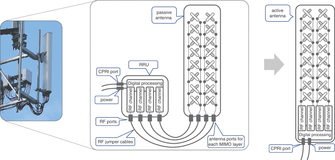
FIGURE 5-3 Passive and Active Antennas
Beamforming
Early attempts to adjust antenna radiation patterns without the use of bulky reflector hardware have led to beamforming and null-forming techniques, which facilitate dynamically adjusting the antenna radiation patterns and reusing the frequency spectrum with high efficiency. Coordinated use of beamforming and null-forming by neighboring base stations significantly reduces interference, thereby allowing many individual subscribers to enjoy high data rates. Beamforming is one of the fundamental features empowering 5G NR radio access technology.
Antennas used in today’s radio access are collections of fancy-shaped elements, intricately arranged into patterns inside the antenna’s radio-transparent enclosure called a radome. Nevertheless, the foundational principles of today’s advanced antennas operation are not overly complicated—everything starts with a dipole. The radiation pattern of a simple vertically installed dipole antenna has a donut shape with radio waves propagating in all directions except vertical (although, in the real world, radio waves may scatter in the vertical direction, albeit greatly attenuated). A typical mobile antenna used in previous generation networks had a number of dipole elements, all connected in parallel to a single antenna port. An RF signal from a BBU’s radio transceiver would be radiated by the dipoles, each forming a donut-shaped electromagnetic field around them. The composite signal of multiple dipoles and the steel plate behind them shape the signal, redirecting it perpendicular to this plate and the column of dipoles, effectively forming a horizontal beam. It is said that an antenna has gain in a particular direction. This simple process helps divert otherwise wasted energy in the desired direction, while shielding the space behind the antenna from the unwanted interference. More technically, this beam is called the main lobe of an antenna radiation pattern, and its width is determined by the number, shape, and relative positioning of individual antenna elements. An antenna with many elements can form quite a narrow beam, but unfortunately the narrower the main lobe is, the more complex-shaped side lobes are created at the same time. Radio engineers and antenna designers seek for an optimal balance in antenna radiation patterns, creating a variety of antennas for different implementation scenarios. Figure 5-4 shows an example of a sector antenna with a column of short dipoles, with side and top views of a combined radiation pattern.

FIGURE 5-4 Simple Sector Antenna with Fixed Radiation Pattern
Popular antenna design features a vertical column of dipoles, redirecting otherwise wasted energy into a vertically focused beam, while covering a whole sector horizontally. These antennas with narrowly focused beams have to be tilted downward to ensure strong signal reception throughout the cell. Instead of mechanical tilting, the antennas once again rely upon the effect of constructive and destructive interference of radio waves emitted by closely placed antenna elements. Each of these antenna elements is connected to an individual analog phase-shifting device that delays the RF signal by a carefully selected, miniscule amount of time to influence the resulting radio waves’ interference peaks and troughs position in space. In simple terms, the effect of shifting phases for individual antenna elements is the tilt of the radiation pattern in the vertical direction and is displayed in Figure 5-5.
The amount of a phase shift for each antenna element can be adjusted, allowing for a change in the vertical direction, and is commonly referred to as an electric tilt. It is important to note that the whole column of antenna elements is fed by a single RF circuit, which is sometimes also called RF chain. Although the RF chain shown in Figure 5-5 primarily refers to a transmitter, a typical RF chain is composed of both the transmitter and receiver.
FIGURE 5-5 Radiation Pattern of an Antenna with Electric Tilt
The electric tilt is just a way to adjust the vertical angle of an antenna radiation pattern or, more technically, to control the antenna’s gain in the vertical direction. It is also sometimes called analog beamforming, as it steers the beam in a downward direction with the use of analog phase shifters. The use of analog phase shifters, instead of mechanical tilting, might sound like a complex solution for a simple task, but in reality, the phase shifters are rather simple inexpensive devices, usually controlled by a stepped DC motor inside the antenna enclosure.17 The amount of tilt is typically controlled through the BBU, via a special tilt control circuit on the antenna. Analog beamforming allows for tilting the antenna radiation pattern with great precision post-installation, without touching the antenna physically.
Analog beamforming was instrumental in improving overall energy efficiency of the radio interface, but it provided little utility to segregate different users or user groups. Indeed, the beams formed by most legacy LTE antennas are vertically narrow, but they still have horizontally wide radiation patterns, thereby illuminating the whole sector. As a result, all mobile devices within the sector have to share the limited number of resource blocks assigned to the base station, thus limiting the transmission data rates. In order to achieve a higher reuse of frequency, or rather resource blocks within a sector, 5G NR technology uses more advanced three-dimensional beamforming (3D beamforming) technology.
3D beamforming relies on the same principle of using multiple elements to form the beam, but this time the beams are formed by two-dimensional arrays, or planar arrays, of antenna elements. With the right spacing between antenna elements, it is possible to create a beam narrow in both the vertical and horizontal dimensions. By applying different phase shifts to the antenna elements in such a planar array, the resulting beam can be steered both vertically and horizontally, while illuminating only a small part of the sector occupied by one or more target mobile devices. By controlling the antenna gain and allowing steering in both the vertical and horizontal directions, 3D beamforming allows more independent transmissions using the same frequency, thus providing higher cell capacity and higher data rates. Figure 5-6 provides a simplified view of 3D beamforming.

FIGURE 5-6 3D Beamforming
Antennas supporting beamforming sometimes are also referred to as beamformers. A typical beamformer is a planar antenna with many elements organized in columns and rows. In an ideal scenario, 3D beamforming can be implemented with all individual antenna elements connected to independent RF chains. These RF chains allow each element to act as an independent antenna transmitting the same signal with different phase shifts. The amount of a phase shift for each antenna element is controlled digitally and applied in their respective RF chains. This is in contrast to analog beamforming, where a single RF chain is used to feed multiple antenna elements while the phase shifts are applied by analog circuits. This beamforming technique is called digital beamforming, which offers great precision in beam width and direction and allow beams to follow individual subscribers.
Unfortunately, controlling dozens or hundreds of antenna elements with individual radio chains is often not feasible and might also be cost prohibitive in the case of mmWave bands. Therefore, for a more practical approach, hybrid beamforming is more commonly used. Hybrid beamforming combines analog beamforming to steer beams in vertical direction, while horizontal steering is achieved via digitally controlled phase shifts applied by individual RF chains. In this scenario, an antenna is divided into a number of different vertical subarrays of antenna elements, which might have different, preset vertical tilts. Each subarray, in turn, is controlled by an independent RF chain. A few subarrays with the same vertical tilt are used to create a beam, which can be dynamically steered in a horizontal direction, illuminating a particular spot in the sector, covering a single or a cluster of mobile devices. When the beams are narrow enough and the side lobes of a particular beam do not interfere with other mobile devices, it is possible to reuse OFDMA subcarriers within a single sector for multiple transmissions at once. Figure 5-7 shows different beamformers.
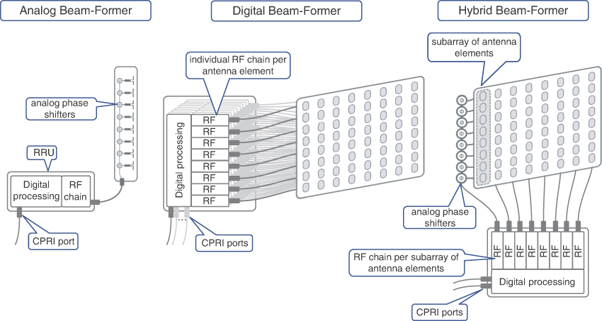
FIGURE 5-7 Analog, Digital, and Hybrid Beamformers
Hybrid beamforming is a cost-effective yet flexible solution for 3D beamforming. Individual mobile devices as well as base stations use special reference signals for sounding purposes, thus probing which beams within the sector are most optimal for a transmission. Sounding signals are transmitted every few dozens of milliseconds over each beam, and based on the feedback from the sounding signal, a mobile device can be switched to another beam, if appropriate.
Massive Multiple Input Multiple Output (mMIMO)
Fundamental for 5G radio technology is the principle of multiple simultaneous data transmissions using the same carrier frequency, known as multiple input multiple output (MIMO), the basics of which were covered in Chapter 3. MIMO technology has been instrumental in increasing spectral efficiency and boosting peak data rates for individual subscribers as well as the entire cell capacity in previous generation mobile networks. 4×4 and 8×8 MIMO systems are commonly used in LTE systems, yet increasing the order of MIMO beyond these numbers is not straightforward. The path to densification of spatial multiplexing collides with the size limitations imposed on the handheld mobile devices. Specifically, the limiting factor is how many antennas can be packed into a single mobile device. Antennas cannot be miniaturized infinitely, and the distance between multiple antennas is determined by the carrier frequency and, therefore, cannot be arbitrary. This limits the number of parallel transmissions in the case of single-user MIMO. Nevertheless, when many mobile devices are served by a cell, it is possible to apply the principles of MIMO and multiplex data streams belonging to different subscribers using the same frequency. This approach is called multi-user MIMO (MU-MIMO), and it helps to significantly increase cell capacity as well as improve data rates for multiple subscribers simultaneously.
MU-MIMO is not limited by the size of an individual mobile device; hence, more antennas can be used at the base station to further increase the order of spatial multiplexing of data streams for different subscribers. When a MU-MIMO system uses a large number of antennas at the base station and more than one antenna is used to communicate with a single antenna at the mobile device, such a system is called massive MIMO (mMIMO).18 However, there are many other definitions of mMIMO systems used by industry engineers. These definitions might focus on various aspects of technology but, as a rule of thumb, a system with 16 or more independent antennas, each one connected to a respective individual RF chain, is considered a mMIMO system.
Strictly speaking, a mMIMO system can be constructed in many ways (for example, a line of antennas distributed over the roof of a building or even stretched over multiple building roofs). As long as all these antennas illuminate a single sector and are part of the same base station, this would be a mMIMO system. In reality, however, the most common mMIMO implementation is based on planar beamformers with many antenna elements. Use of beamformers in mMIMO systems is so popular that sometimes beamforming is used as a synonym for mMIMO, which, of course, is not technically accurate. Beamforming is just one of the applications of a mMIMO system.
Interestingly enough, modern beamformers (both analog and hybrid) use a clever technique to conserve precious space on the cell tower by reducing antenna size. This technique leverages the electromagnetic phenomenon of polarization, where electric and magnetic fields oscillate in a specific direction. Two polarized radio waves are said to be cross-polarized and do not interfere when their respective electric and magnetic fields oscillate in orthogonal directions. When two antenna elements are cross-polarized, they emit radio waves with little to no interference. Thus, these antenna elements can be placed one behind the other, effectively squeezing two antennas into one.
One important consideration of MIMO transmissions using hybrid and digital beamforming techniques should be noted here. As was explained in Chapter 3, the concept of MIMO transmission is the use of different spatially diverse paths to transmit multiple data streams, with each distinct data stream representing a separate MIMO layer. In digital and hybrid beamforming techniques, however, multiple RF chains are used to form a single beam, and all these RF chains transmit, in fact, the same data. Therefore, the number of independent MIMO layers offered by hybrid and digital beamformers is not equal to the number of RF chains. This can be further exemplified by the antennas shown in Figure 5-8, which shows 4×4 MIMO (often called 4T4R to signify the transmit and receive RF chains respectively) and 16×16 (also called 16T16R) mMIMO antennas.

FIGURE 5-8 4T4R MIMO and 16T16R mMIMO Antennas
The legacy 4T4R MIMO antenna shown in Figure 5-8 is used as a four-layer MIMO system—2× columns, 2× different polarizations, creating a total of four independent antennas. Each of these four antennas is connected to an individual RF chain and may transmit or receive distinct data streams. On the other hand, the 16T16R mMIMO antenna shown in the same figure is a hybrid beamformer. In this particular example, the antenna is organized into vertical subarrays of four antenna elements each. There are eight subarrays of each polarization, with a total of 16 independent subarrays. Each subarray relies on analog phase shifters to achieve downward tilt and is connected to an individual RF chain. The total number of RF chains required to drive this antenna is 16, defining its 16T16R mode of operation. However, to implement horizontal beam steering using this antenna, a few individual RF chains, connected to subarrays of the same polarization in a single row, have to transmit the same data, applying various phase shifts digitally. Hence, in the case of four subarrays used in horizontal beam steering, this particular organization of the 16T16R beamformer can offer four independent MIMO layers.
It is possible to use the same beamformer with wider horizontal beams and less precision in horizontal steering by reducing the number of RF chains for each beam to only two. This way, the same antenna can provide up to eight independent MIMO layers. The number of RF chains and MIMO layers is critical for proper radio access network dimensioning. Chapter 10, “Designing and Implementing 5G Network Architecture,” covers the topic of xHaul dimensioning in greater detail.
Some obvious benefits of mMIMO application in 5G networks include improved spectral efficiency, faster and more robust transmission, and energy efficiency among others. On the flip side, it can be challenging to implement with FDD, due to the lack of channel reciprocity, as explained in Chapter 2. Also, it might be expensive and hard to build mMIMO systems in mmWave bands.
Multi-Radio Connectivity
Strictly speaking, the transmission of subscriber data over multiple radios is not a new 5G feature. Ever since the introduction of MIMO, multiple radios are being used to transmit data over spatially diverse paths, but such transmissions normally utilize radios residing on the same cell site/tower and connected to the same BBU. Similarly, the carrier aggregation technique relies on multiple radios, and although it is possible to leverage remote radio units (RRUs) placed on different towers, these have to belong to the same eNodeB or, its 5G equivalent, gNodeB. In other words, there is only one RF scheduler, controlling the allocation of resource blocks over the air interface for a given mobile device.
Another example of multi-radio connectivity introduced in LTE Release 11 is Coordinated Multi-Point (CoMP) transmission.19 Substantial interference from the neighboring cells near the cell borders is always a serious challenge for mobile radio engineers and is traditionally addressed by using appropriate frequency reuse patterns. Restrictive frequency reuse patterns help to mitigate interference problems but dramatically reduce spectral efficiency. As explained in Chapter 3, LTE networks allowed moving away from strict allocations of frequencies in the whole cell by dividing cells into inner and outer parts. The same frequency channels can be used in the inner parts of the neighboring cells, yet the outer parts still have to follow stringent rules of frequency reuse patterns. One of the goals of the CoMP transmission technique is to solve this challenge. CoMP defines various scenarios ranging from coordination only within a single site, mainly between multiple sectors of the same eNB, to coordination between neighboring cells, which could be a combination of either macro-macro or macro-pico cells.
The basis of CoMP technology is the coordinated scheduling of radio resources used by neighboring radios or, in 3GPP terminology, transmission points (TPs). Multiple TPs can be represented by a collection of RRUs, which can be controlled by the same or different eNBs. In the latter case, the scheduling information must be exchanged over the X2 interface to achieve the desired cooperation across eNBs. Nevertheless, all coordinated transmissions are considered by the mobile device as if they are controlled by a single RF scheduler.
A few different approaches to implement radio resource scheduling by multiple TPs are defined under the CoMP umbrella:
Joint transmission: Multiple TPs can send the same symbols on the same frequency, for the same subscriber, and if coordinated properly, can greatly improve signal quality received by a mobile device. However, such coherent joint transmission requires very accurate coordination and, thus, is very sensitive to the latency between participating TPs and/or eNBs.
Coordinated scheduling/coordinated beamforming: Neighboring TPs coordinate scheduling of transmissions using certain beams, where respective low-gain radiation pattern (null) points in the direction of subscriber, attached to a neighboring cell, participating in coordination. The benefit of using this approach is increased spectral efficiency, and it can also be combined with the joint transmission method.
Dynamic point selection: A transmission point sending the data to the subscriber can change every subframe, with one TP used at a time. Dynamic point selection enables reacting to quickly changing transmission conditions by changing the transmission point, thus improving overall reliability.
Figure 5-9 illustrates these CoMP approaches.

FIGURE 5-9 CoMP Transmission Scheduling Methods
CoMP transmission is an effective way to improve signal quality, reliability, and data rates at the edges of cells and in picocells within macrocells. CoMP techniques can be instrumental in improving signal robustness in 5G URLLC scenarios, preventing potential signal dropouts in complex industrial environments involving mission-critical applications of M2M communications. On the other hand, CoMP techniques impose tight latency and reliability requirements on backhaul for inter-eNBs/gNBs coordination. It is considered that CoMP relies on an ideal backhaul and hence can greatly benefit from C-RAN architectures, where BBUs are co-located and have virtually no latency between them. Application of CoMP in 5G networks is an area of active research among 3GPP members.20
Dual connectivity is another form of multi-radio connectivity that was introduced for LTE in 3GPP Release 12. This approach was further generalized and expanded in Releases 15 and 16 and called Multi-Radio Dual Connectivity (MR-DC).21 Unlike CoMP, where coordination and scheduling happen using a single RF scheduler, MR-DC involves higher layers of 5G protocol stack (more details on 5G protocol stack are covered in the upcoming sections), allowing RF schedulers to operate independently in two participating RAN nodes, such as eNB or gNB, which allows operation in non-ideal backhaul environments. However, this connectivity model requires mobile devices to support simultaneous communications with two separate eNBs/gNBs.
It is anticipated that current large mobile network deployments will coexist with 5G networks for quite some time and will require well-defined procedures to transition from previous generation to 5G network. Some of these deployment challenges can be addressed through the use of standalone (SA) and non-standalone (NSA) 5G deployments, where 5G NR can communicate with the previous generation packet core—Evolved Packet Core (EPC).
MR-DC can operate in such heterogeneous environments and use:
en-gNB: A 5G NR RAN node, which is capable of establishing user-plane communication with EPC and works as a secondary node with the control plane established over the X2 interface via the main eNB.
ng-eNB: An LTE RAN node, which can establish control- and user-plane communication with 5G Core. These nodes also establish communication with gNB nodes over 5G’s Xn interface.
MR-DC defines two roles for RAN nodes: master node (MN) and secondary node (SN). MN is responsible for all regular tasks of a typical eNB or gNB in a single connectivity deployment; that is, it establishes both control- and data-plane connections with the mobile core, controls data transfers, and schedules radio resources. Additionally, MN establishes a control-plane connection with the SN over the X2 interface in the case of eNB—or its equivalent, Xn interface, in the case of gNB. The secondary node also establishes a user-plane connection with the mobile core, allowing both the MN and SN to schedule their own radio resources separately, through the use of respective radio bearers. However, 3GPP defines another way of delivering user data, through the use of a split bearer. This mechanism allows the bearer to be terminated at the MN, while pooling the radio resources of both the MN and SN. The user data stream is then split between the MN and SN and is transported over the X2/Xn interface between these two RAN nodes. The use of split bearers can result in a significant amount of user-plane data exchanged over X2/Xn interfaces.
Note
Use of the term master is only in association with the official terminology used in industry specifications and standards, and in no way diminishes Pearson’s commitment to promoting diversity, equity, and inclusion and challenging, countering, and/or combating bias and stereotyping in the global population of the learners we serve.
A number of different permutations for dual connectivity are specified by 3GPP, such as whether RAN nodes connect to 5G Core or to legacy EPC, if a gNB or an eNB is a master node, and what is being used as a secondary node. Figure 5-10 shows a few options of using MR-DC with EPC and 5G Core (5GC) network.
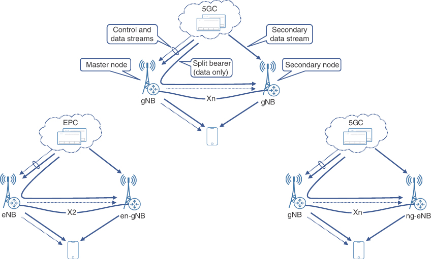
FIGURE 5-10 Multi-Radio Dual Connectivity Options
It is important to note that carrier aggregation can be used along with MR-DC connectivity options; however, the number of component carriers aggregated over two cells or cell groups cannot exceed 32, which is defined as the maximum number of component carriers in 5G NR.22
Dynamic Spectrum Sharing
Transition to a newer radio access technology is always a challenging and complex endeavor. Thanks to 5G NR capabilities to communicate with EPC, it is possible to implement gradual deployment of 5G NR technology. Yet, this provides little relief to the spectrum repurposing aspect of this transition.
Spectrum repurposing, or reallocation of bands and frequencies from older to newer radio access technology, can be complicated, especially in the areas of high traffic. In a simple and direct approach, the newer radio access technology uses a separate set of frequencies, when coexisting with the older technology. Although it might be a feasible approach to deploy 5G NR using high bands, as these are not used by LTE, it requires much more planning when low and mid bands have to be reused. The low- and mid-band frequencies are typically a very scarce resource, as these provide the sweet spot between capacity and optimal propagation. Providing 5G radios with their own set of mid- and low-band channels typically requires carving those channels out of current LTE allocations. This task requires careful resource planning by radio engineers, as it is not easy to find an optimal balance between 5G and 4G resources. Repurposing spectrum statically could result in an imbalance, where the previous generation users might not get enough RF resources, while resources assigned to another radio access technology are wasted in the absence of a substantial number of subscribers.
Dynamic spectrum sharing (DSS) helps to avoid such suboptimal scenarios and offers flexible distribution of radio resources, adjusting to the fluid ratio between 5G and 4G subscribers in a cell.
DSS leverages the fact that both LTE and NR use OFDM and can be deployed with the same subcarrier frequency spacing and symbol duration. In fact, NR was designed with such interoperability in mind. In DSS setup, LTE and NR radio nodes, serving the same cell, rely on coordination between their radio resource schedulers, such that resource blocks belonging to the same channel can be used by one of these radios, as needed. This allows the use of the same channel on both radios, without subdividing for hard allocations to a particular radio: NR or LTE.
DSS is an area of active research in 3GPP.23 Most current deployments rely on a proprietary interface between the eNB and gNB for scheduler coordination, thus limiting the choice of RAN node vendors to match those already deployed.24
Vehicle-to-Everything Communication
Originally introduced as an LTE study item, Cellular Vehicle-to-Everything, or C-V2X, became a standard in Release 14 and was adopted for 5G NR implementations in Release 16.25, 26 C-V2X communication is aimed at providing additional communication channels between vehicles, and between vehicles and other road users as well as parts of road infrastructure.
C-V2X uses a concept of a sidelink, effectively turning a vehicle into a RAN node by extending connection from nearby eNB/gNB to other mobile devices. It is also possible for a single vehicle to coordinate direct communications between a group of vehicles, thus creating a mesh of direct interconnections, enabling robust communication between multiple vehicles and a network.
The Vehicle-to-Everything communication approach encompasses a number of different use cases: Vehicle-to-Network (V2N), Vehicle-to-Vehicle (V2V), Vehicle-to-Infrastructure (V2I), and Vehicle-to-Pedestrian (V2P). Vehicles communicating with each other and with the road infrastructure may coordinate different parameters, such as speed, lane selection, and even path, based on dynamic conditions on the road. Such communication and coordination make transportation much more effective and safer, especially in the case of self-driving cars. New safety features, such as “Do not pass warning,” can be a result of V2V communication, warning a driver or a self-driving car about the upcoming traffic on non-divided highways.27 All these features require strict coordination and impose new and stringent requirements on the underlying transport network, addressed by the implementation of URLLC-type services. C-V2X communications can also improve safety of pedestrians by warning nearby cars about their presence, complementing obstacle-detection systems currently adopted by some vehicles.
C-V2X communications standards and implementations are still in their infancy, but this is an area of active research and growth. It is anticipated that vehicular communications become a widely adopted phenomenon and enable future innovations in transportation.
RAN Virtualization and Decomposition
Centralized RAN (C-RAN) architecture was proposed around 2010 by China Mobile Research Institute, in collaboration with hardware vendors such as Intel, ZTE, Nokia, Huawei, among others.28 It was originally geared toward offering a sustainable green solution for RAN, while offering cost savings through BBU pooling at a centralized location. It had been shown that cell sites are responsible for more than 70% of overall power consumption in a mobile service provider’s network, with over 50% of each cell site’s power consumption going toward air conditioning.29 The C-RAN cost reductions come from a leaner cell site footprint, significantly lower cooling and power costs, and lower maintenance costs due to reduced truck rolls to every cell site in case of BBU issues. Although C-RAN started primarily as a green initiative, the BBU pooling offered other advantages such as improvement in RAN utilization through increased spectral efficiency, reduced interchannel interference, and simplified use of CoMP transmission.
Despite these benefits of real estate and power savings as well as RAN efficiency that mobile operators could realize by using C-RAN architectures, they still had to deploy the same number of these chassis-based BBUs and would not be able to optimize BBU usage across cell sites. This was because the BBU was still a purpose-built, vendor-specific, physical hardware and was allocated to its specific cell site. Based on the subscriber load, some BBUs might be underutilized while others might be oversubscribed, depending on factors such as the cell site location they are serving and time of the day. The net result was the pooling of physical BBUs in a central location, but not the sharing of baseband-processing resources across cell sites. The transition toward the virtualization of RAN components offered a solution to this inefficiency.
Centralized, Cloud, and Virtualized RAN
Network Functions Virtualization (NFV) was initially proposed in 2012 (around the same time as 3GPP Release 11) by a consortium of service providers as a solution for cost and complexities associated with vendor-locked hardware.30 The solution proposed through NFV was to decouple the hardware and software layers and, by using virtualization techniques, remove the vendor lock-in for devices performing network functions. Dynamic scalability, deployment velocity, and easy upgradability through use of orchestration and automation tools were also among the goals of NFV.
General-purpose compute functions were first to be virtualized and decoupled with hardware. Soon after, new networking startups started offering virtual networking functions (VNFs) for various networking roles such as firewall, NAT, and route reflectors. These initial VNF implementations were predominantly focused on functions that relied heavily on software processes; however, the functions that had more dependency on the hardware took longer to be virtualized. BBU functions were also considered for virtualization and dubbed virtual BBU (vBBU).
New RAN equipment vendors such as Altiostar, COTS hardware vendors such as Dell, and silicon providers such as Intel partnered to offer vBBU solutions. Though it was demonstrated that vBBU would offer many benefits over specialized hardware, it was not commonly deployed as a single VNF but rather split into two RAN components—the distributed unit (DU) and the centralized unit (CU), which are discussed in detail in the next section.
The effort to drive RAN architecture toward the use of software-based, virtualized RAN components was given the name Virtual RAN (vRAN). The vRAN architectures gained industry momentum around the time when virtualization of applications was often equated with a transition to cloud-based environment. This perception led to the terms Virtual RAN and Cloud RAN being used interchangeably. Some vendors preferred the term Cloud RAN, whereas others opted to use vRAN terminology. More recently, however, a clear distinction has started to emerge between the two terminologies and the underlying architecture they represent. Virtual RAN (vRAN) now refers to the generic drive towards the use of software-based RAN components instead of physical hardware such as the BBU. On the other hand, Cloud RAN is now considered a subset of vRAN where the software-based RAN components are designed to be cloud-native. Later sections of this chapter will expand on the characteristics of cloud-native applications.
Note that the term Cloud RAN can also be abbreviated as C-RAN, which can easily be confused with Centralized RAN. Due to the similar abbreviations, and a lack of clear definitions, casual industry observers sometimes use the terms Centralized RAN and Cloud RAN interchangeably, which is not accurate. Centralized RAN refers to an architecture where the BBU or its decomposed RAN components (that is, the CU and DU) are moved away from the cell site and placed in one or more central locations. Cloud RAN, as mentioned above, is a subset of vRAN, and refers to an implementation where the RAN components are virtualized to be cloud-native. The virtualized RAN components (whether for vRAN or Cloud RAN) are referred to as virtualized CU (vCU) and virtualized DU (vDU), and could be placed at the cell site (that is, a D-RAN architecture) or in one or more DCs (that is, a Centralized RAN architecture).
It is helpful to think of Distributed/Centralized and Virtual/Cloud RAN architectures as orthogonal dimensions. Distributed or centralized RAN deployments could use physical RAN components (for example, a BBU or CU and DU appliance) or software-based RAN components (that is, a vRAN or Cloud RAN deployment). As mentioned previously, the software-based RAN components are usually decomposed into a vCU and vDU. Similarly, a vRAN deployment (including Cloud RAN deployment) could use a Distributed RAN model (where RAN components are distributed across Cell Sites) or a Centralized RAN model (where RAN components, that is, the CU and/or DU are placed in one or more Data Centers).
This book will use the term vRAN when referring to the architecture pertaining to software-based RAN components, which implicitly covers Cloud-RAN as well. The terms Centralized RAN and Cloud RAN will not be abbreviated from this point on to avoid any confusion. The term decomposed RAN will be used to refer to splitting of BBU into a CU and DU, which may or may not be virtualized and may be placed at the cell site, remotely at a data center, or a combination of the two. The placement of decomposed RAN components is discussed in the next section.
Virtualized RAN (vRAN) Architecture
A BBU performs a lot of specialized digital signal processing, converting radio traffic from RU into IP, and vice versa. The functions performed by BBU could be classified into two broad categories—real-time and non-real-time. Real-time functions would include scheduling, interference coordination, precoding MIMO and beamforming, modulation, and error correction, while non-real-time functions include bearer configuration, connection management, subscriber handovers, data encryption, header compression, and various operations, administration, and maintenance (OAM) tasks. In short, BBU tasks associated with direct traffic processing and forwarding are considered real-time functions, whereas management and control-related functions would classify as non-real-time.
Redesigning a BBU with functions split across two separate entities based on task classification made it easier for BBU to be virtualized. This was further supported by the performance improvements of available COTS hardware. The real-time functions are grouped in the DU, whereas the non-real-time functions were grouped in the CU. The decomposed vRAN architecture, that is, the virtualized CU and DU, is quickly becoming the go-to solution for new RAN deployments.
Given that the DU would be required to perform most real-time functions, it needs to be placed close to the cell sites to ensure low-latency communications with the RRU. Hence, the DUs should be hosted at the far edges of a mobile communication network, closer to the cell sites. The data center hosting the DU functions, depending on the number of cell sites it services, could be composed of just a few servers connected to the aggregation routers or a few racks of equipment. In a vRAN architecture, this DC is referred to as a far-edge data center. The transport network connecting the cell sites and the far-edge DC is still called the fronthaul, with CPRI-based RU to DU communications that could use either packet-based or WDM-based transport, as previously described in Chapter 3. Newer RAN components may use an enhanced version of CPRI, called eCPRI, which is discussed later in this chapter. As such, a fronthaul network might need to carry both CPRI and eCPRI traffic.
CU, on the other hand, is responsible for non-real-time functions and could tolerate higher latency compared to the RU-DU connectivity. So even though CU is part of the RAN infrastructure, it can be placed further from the RU compared to the DU. The CUs could be pooled in edge data centers that are placed farther away from the cell sites in comparison with a far-edge DC, but still much closer than a traditional centralized DC. The network that connects the CUs to DUs is called the midhaul. The umbrella term xHaul, which was previously used for a combination of backhaul and fronthaul networks in Centralized RAN, is also used to refer to midhaul. Figure 5-11 shows the traditional D-RAN, present-day Centralized RAN, and the next generation vRAN architectures and their corresponding xHaul domains.

FIGURE 5-11 Distributed, Centralized, and Virtualized RAN
Table 5-1 outlines the latency requirements and typical distance allowed for fronthaul, midhaul, and backhaul networks.31, 32
TABLE 5-1 xHaul Networks and Their Characteristics
xHaul Domain | Purpose | Max One-Way Latency* | Max/Typical Distance |
|---|---|---|---|
Fronthaul | RU–DU(5G)/BBU(4G) connectivity | ~100 usec (4G/LTE)* ~150 usec (5G)* | 20/10 km |
Midhaul | DU–CU connectivity | ~ few milliseconds | 200/40–100 km |
Backhaul | BBU(4G)/CU (5G)–5GC connectivity | ~ few milliseconds | 200/40–100 km |
* These numbers are guidelines by various standard bodies. Exact latency tolerance between RAN components should be provided by the equipment vendor and must be validated in test labs before deployment.
An xHaul implementation in vRAN can use any combination of fronthaul, midhaul, and backhaul networks, depending on the placement of the CU and DU relative to the RU. For instance, the DU and CU can both be co-located, but away from the cell site, in which case only a fronthaul network exists between the RU and the data center hosting the DU and CU. In other instances, the DU might be placed at the cell site with the RU. In this case, the fronthaul is collapsed within the cell site, while a midhaul network connects the cell site to the CU hosted in the edge DC. Another example of a co-located RU and DU is the Active Antenna System for mmWave bands, where the DU is integrated into the RU and antenna panel. This allows all real-time functions to be performed at the cell site, thus eliminating the need for a fronthaul network. Lastly, deploying the physical or virtual BBU, or its decomposed components (DU and CU), at the cell sites results in a traditional D-RAN-like architecture with a backhaul network connecting the cell site containing both the DU and CU to the 5G Core network. Figure 5-12 illustrates these various deployment models.

FIGURE 5-12 DU and CU Placement in Various vRAN Deployment Models
When a transformation to vRAN is being planned, there might be instances where a C-RAN hub could be rebranded as either an edge or far-edge DC, depending on its location and distance from existing or newly installed cell sites. In other cases, as cellular networks and cell sites continue to grow, there may be a need for new data centers. In a vRAN environment, edge DCs are typically fewer in number than far-edge DCs and, thus, CUs located in these edge DCs may provide services to cell sites over a larger geographical area. The edge DCs also tend to be larger than far-edge DCs, resembling a traditional data center spine-leaf architecture, and could be used to house additional components, not just the CU. There typically is a one-to-many relationship between the CUs and DUs, and both these functions are part of the 5G base station, known as gNodeB (gNB).
gNodeB
NodeB in 3G and evolved NodeB (eNodeB or eNB) in 4G LTE have been responsible for terminating the subscriber’s air interface and performing baseband traffic processing. In 5G networks, this functionality is performed by a gNodeB (gNB), short for next-generation NodeB, where n is simply omitted for better readability. There are fundamental architectural differences between the gNB and its predecessors, most notable being the decomposition of BBU functions. Next Generation RAN (NG-RAN) architecture, originally introduced in 3GPP Release 14 and refined in subsequent releases, conceptualizes the gNB architecture where the functions of BBU are split into the centralized unit (CU) and distributed unit (DU). 3GPP Release 15 officially named these functions the gNB-CU and the gNB-DU.
As per 3GPP specifications, a gNB can contain one gNB-CU and one or more gNB-DUs. 3GPP does not limit the number of DUs in a gNB but rather leaves it up to individual deployments. The number of gNB-DUs in a gNB is typically a derivative of processing capabilities and resources available on the gNB-CU.
The DUs connect to the CU using an F1 interface, while the CU connects to the 5G Core using NG interfaces, which is a collective name given to interfaces from 5G RAN to 5G Core. Various NG interfaces are discussed in the “5G Core Network” section.
An Xn-C interface, equivalent of an X2 interface in 4G LTE, is used for connectivity between gNBs and terminates on the gNB-CU. It must be reiterated that all these interfaces, like other 3GPP-defined interfaces, are logical in nature and use the underlying network infrastructure to establish connectivity.
For better scale and more granular separation of functions, the gNB-CU can be further decomposed into gNB-CU-CP (control plane) and gNB-CU-UP (user plane). The gNB-CU-CP is primarily responsible for control and management tasks of the gNB-CU’s functions, such as selecting the appropriate gNB-CU-UP for user data and establishing an F1 interface connection between the gNB-CU-UP and gNB-DU. On the other hand, gNB-CU-UP transports user data between the gNB-DU and gNB-CU and provides functions aimed at improving data speed, efficiency, and reliability through data retransmission in case of radio link outage, status reporting, and redundant data discarding.
A gNB-CU can consist of a single gNB-CU-CP instance and one or more gNB-CU-UP instance(s), thus allowing both the control and user planes to scale and operate independently of each other. The gNB-CU-CP and its corresponding gNB-CU-UPs communicate through the E1 interface. The F1 interface between the DU and CU is subdivided into F1-Control Plane (F1-CP) and F1-User Plane (F1-UP) to provide connection from gNB-DU to gNB-CU-CP and gNB-CU-UP, respectively. A gNB-DU could connect to a single gNB-CU-CP and one or multiple gNB-CU-UPs, as long as all those gNB-CU-UPs are managed by the same gNB-CU-CP. Figure 5-13 provides an overview of these various gNB components and interfaces.34

FIGURE 5-13 gNodeB Components and Interfaces
Together, the gNB-DU and the gNB-CU (along with the RRU) make up the gNB in the Next Generation RAN (NG-RAN) architecture. However, exactly how the BBU functions are split between the CU and DU has been a topic of intense discussion in various standardization bodies and organizations. As these splits have significant implications on the overall network architecture, the next section will discuss the various BBU functional split options across the RU, DU, and CU.
Understanding the RAN Functional Splits
The relocation of the baseband unit (BBU) from the cell site to a centralized location was the beginning of RAN decomposition in mobile networks that was further accelerated with the introduction of BBU functional splits. The CU and DU, or rather their more commonly used virtualized versions, are an integral part of current and future vRAN deployments. The capabilities of CU and DU depend on the functional split option implemented. The functional split option, more commonly called the split option, refers to precisely how the 5G protocol stack gets divided between the CU and the DU, and whether or not some of the baseband processing is offloaded to the RU. To understand the split options, it’s useful to first understand the functions performed by the BBU at various layers of the 5G protocol stack.
5G Protocol Stack Overview
The 5G protocol stack consists of three layers, which can be loosely correlated, though not directly mapped, with the bottom three layers of the OSI model.35, 36 Layers in the 5G protocol stack are mostly similar to those in 4G, but the tasks performed at each layer have been enhanced and new functions added to support 5G services. As shown in Figure 5-14, the lowest layer of the 5G protocol stack is called the physical layer (PHY). Layer 2 is further subdivided into the Media Access Control (MAC), Radio Link Control (RLC), Packet Data Convergence Protocol (PDCP), and Service Data Adaptation Protocol (SDAP) layers. The Radio Resource Control (RRC) and IP encapsulated PDCP frames make up Layer 3 of the 5G protocol stack.

FIGURE 5-14 5G Protocol Stack and Functions Performed by BBU
The physical layer (PHY) performs functions such as upstream and downstream link adaptation, modulation and encoding, signal power adjustment, and assisting user equipment in initial cell search and signal acquisition. The physical layer defines the frame format based on the FDD or TDD duplexing schema and the use of appropriate encoding—OFDMA in the downlink and SC-FDMA for the uplink—which have previously been discussed in detail. The physical layer is responsible for assisting in advanced antenna functions such as MIMO layer processing, beamforming, and transmission diversity management.37
The MAC layer, which is a sub-layer of Layer 2, is responsible for scheduling, prioritizing, multiplexing, and demultiplexing data to and from the mobile devices. 5G’s MAC layer has also been enhanced to support additional physical layer features such as beamforming and transmission diversity. Data integrity verification and error correction through retransmissions or Forward Error Correction (FEC) are also done at the MAC layer.
The RLC layer, also part of Layer 2, is primarily responsible for segmentation, reassembly, and buffering of protocol data units (PDUs). In certain modes of operation, the RLC sub-layer might require acknowledgment of receipt from the remote device, thereby adding transmission overhead but providing additional capabilities such as duplicate traffic detection and protocol-level error correction.38
The third sub-layer within Layer 2, the PDCP layer, is responsible for the actual data transmission for both the control-plane and user-plane traffic over the radio bearers. This sub-layer also provides data security and integrity through encryption as well as header compression and duplicate traffic detection. The PDCP sub-layer may customize processing for various 5G service types (for example, header compression and decompression may not be implemented for URLLC services to reduce latency).
In 4G LTE implementation, traffic from the PDCP sub-layer is passed on as IP data to the packet core. 5G specifications, however, add another sub-layer called SDAP in the protocol stack. SDAP’s sole purpose is to build upon the existing QoS capabilities. It provides QoS for user-plane traffic by mapping a traffic flow to a radio bearer based on its requirements.39 Layer 3 of the 5G protocol stack is the RRC layer, which is primarily focused on management function and does not explicitly participate in traffic forwarding. RRC is responsible for establishing, maintaining, and releasing radio bearers (both signaling and data bearers). Mobility functions such as mobile device handover and cell-selection functions are managed by the RRC layer as well. RRC also closes the feedback loop with the PHY layer by analyzing measurements of radio signals and ensuring appropriate resources are allocated on the air interface.
Based on the tasks and functions performed by each individual layer, it is easy to infer that lower layers such as physical, MAC, and RLC are responsible for more real-time functions, such as encoding, scheduling, segmentation, and reassembly, that require near constant communication with the RRU. On the other hand, the higher layers—PDCP, SDAP, and RRC—are involved with non-real-time tasks such as data compression, encryption, and configuration management.
This clear distinction forms the basis of the CU-DU functional splits, where the real-time functions (performed by lower layers, that is, PHY, MAC, and RLC) are delegated to the DU, whereas the non-real-time functions of the PDCP and upper layers are assigned to the CU. Given the complexities of the tasks performed by the BBU and the closed nature of the RAN ecosystem, more variations in functional splits were introduced for both the high and low layer split, as explored in the next section.
Split Options
RAN has historically been a closed, proprietary system where RAN equipment vendors would engineer their products as they see fit. There is widespread agreement among standard bodies, equipment vendors, and mobile network operators regarding the benefits of a decomposed vRAN architecture and the need for CU and DU functional split, but there are also different opinions on how to split the BBU functionality between the two. Given the complexities of the tasks performed by the BBU and the closed nature of the RAN ecosystem, 3GPP defined multiple split options in Release 14. This allowed the RAN equipment vendors the flexibility to implement the BBU functional split based on their individual product architecture, while still adhering to the 3GPP specifications. These split options, aptly named Options 1 through 8, provide a possibility to split the BBU functionality into CU and DU at every individual layer in the 5G protocol stack and, in some cases, within the layer itself, as shown in Figure 5-15. It’s worth noting that some split options, such as Options 2, 3, and 7, have multiple sub-split options; however, Figure 5-15 shows only the sub-splits for Option 7, which is more commonly used in the industry.40

FIGURE 5-15 3GPP-Defined BBU Functional Split Options
The BBU functionality is split between the CU and DU based on the split option chosen by the RAN equipment manufacturer. Each of the split options represents a deliberate decision on how processing will be distributed between the CU and DU. If more processing is done on the DU, less processing is needed on the CU, and vice versa. The distribution of functions between the two (that is, the choice of split option) also determines the bandwidth required between the CU and DU. A brief description and typical uses of each split option are mentioned in the list that follows:41
Split Option 8: PHY–RF Layer Split: This is not a new split option but rather a formalization of the traditional deployment where the RF processing is done on the RU, while 5G protocol stack processing is performed at a centralized location in the BBU. Option 8 continues to use CPRI transport between the RRU and BBU and is already used in Centralized RAN deployments. This option requires very high amounts of bandwidth across the fronthaul network and has strict latency requirements between the RRU and BBU, limiting the maximum distance to 20 km or less.
Split Option 7: Intra-PHY Layer Split: This option splits the PHY layer functionality between the DU and CU. Option 7 defines even more granular split choices within the PHY layer called Options 7-1, 7-2, and 7-3. Each of these split options defines a list of PHY layer tasks, such as encoding, modulation, MIMO, and beamforming processing, to be divided between the DU and CU. 3GPP allows the use of different sub-options in uplink and downlink directions for added efficiency. For instance, Option 7-1 or 7-2 could be used for uplink, and at the same time Option 7-3 could be used for downlink. Using any of these split options greatly reduces the bandwidth between the DU and CU, but does not relax latency restrictions between the two. Option 7, along with Option 6, is one of the favored split options by 3GPP.
Split Option 6: MAC–PHY Layer Split: This is where all MAC and higher layer functions reside in the CU, while PHY layer functions are delegated to the DU. Option 6 further reduces the bandwidth requirements between the CU and DU but does not offer much in terms of relaxing latency requirements.
Split Option 5: Intra-MAC Layer Split: This option splits the functions performed by the MAC layer into High MAC and Low MAC. CU performs the High MAC functions, such as centralized scheduling and intercell interference coordination, along with RLC and PDCP functions, whereas DU performs the Low MAC, PHY, and RF functions. Option 5 relaxes the latency requirements between the CU and DU, thus allowing longer distances, but is more complex to implement and thus not favored over Split Options 6 and 7.
Split Option 4: RLC–MAC Layer Split: This option delegates the functions of the RLC, PDCP, and RRC layers to the CU, whereas the DU performs the MAC and lower-layer functions. Option 4 is not used, as it does not offer any discernible advantages over other split options.
Split Option 3: Intra-RLC Layer Split: This option further divides the RLC layer functions of segmentation, reassembling, buffering, and error correction into High RLC and Low RLC. In this split option, the High RLC, PDCP, and RRC functions reside in the CU, whereas the Low RLC, MAC, PHY, and RF functions reside in the DU.
Split Option 2: PDCP–RLC Layer Split: This option has been recommended by 3GPP for standardizing the CU–DU split. Using Option 2, the PDCP and RRC layers reside in the CU, whereas the DU performs the functions of the RLC and lower layers. The functionality offered by this split option has previously been finalized in 4G LTE, and, thus, it makes Option 2 much more feasible for standardization with marginal incremental efforts. Option 2 offers much lower bandwidth as compared to its lower-layer counterparts as well as much better latency tolerance between the CU and DU. Option 2 has become the industry standard for implementing the so-called Higher Layer Split (HLS) between the CU and DU. More details on HLS and its counterpart, the Lower Layer Split (LLS), is covered in the next section.
Split Option 1: RRC–PDCP Layer Split: This option is also allowed by 3GPP. In this split option, only the RRC functions are implemented in the CU while the rest of the functions of the 5G protocol stack are performed by the DU. If implemented, this option results in a complex and bulky DU and thus is typically not used.
Single vs. Dual Split Architecture
The split options can be grouped into two categories: Options 1 and 2 map to the non-real-time functions and are classified as Higher Layer Splits (HLS), while Options 3 through 8, which map to real-time functions, are called Lower Layer Splits (LLS).
In a typical 5G MCN deployment, both the HLS and LLS options are utilized simultaneously, resulting in disaggregating the BBU into the DU and CU, as well as offloading some of the functionality to the RU—all working together to implement a decomposed, virtualized RAN architecture. HLS is used to implement the CU functions, whereas one of the LLS options is used to further disaggregate the functions of lower layers between the DU and RU. For instance, if the RAN equipment vendor chooses to implement HLS Option 2 for CU and LLS Option 6 for DU, then:
The CU must implement the PDCP and RRC layer functions.
The DU must implement the MAC and RLC layer functions.
The RU must implement the PHY layer functions.
Consequently, if Option 7 is used for the DU, which is an intra-PHY split, then the RU must implement some of the PHY functionality, while the DU implements the rest of PHY layer functions, along with the MAC and RLC functions. In other words, depending on the LLS option used, the RU now needs to perform additional processing of the RF signal before sending it over to the DU. The same is true in the reverse direction. The use of dual split options is also documented in the IEEE 1914.1 standards. Figure 5-16 shows various single split and dual split architecture scenarios.

FIGURE 5-16 Single vs. Dual Split vRAN Architectures
Allowing the DU to offload some of its functionality to the RU through an LLS option serves a few purposes. First, it provides the RAN equipment vendor with the flexibility to distribute the real-time functions of the BBU between the RU and DU as they see fit. Second, offloading some of the DU functions to the RU reduces the bandwidth required in the fronthaul network. Lastly, certain LLS options may be better suited for the latency-sensitive nature of communication between the RU and DU. On the flip side, moving too much processing on the RU may make it bulkier, power-hungry, and more susceptible to overheating. The RUs are typically external, pole-mounted devices, where such changes in the hardware form factor could be undesirable. The key is therefore to choose an LLS option that is best suited to provide an optimal balance between too much or too little processing on the RU. To that end, Options 8 and 7 have emerged as the frontrunners of industry adoption and have also been the focus of standardization by various industry bodies.
Choosing a Suitable Split Option
While 3GPP has standardized the use of Option 2 for HLS, it did not definitively recommend a specific LLS option.42 Over the past few years, Option 7 has emerged as the frontrunner of various standardization efforts. To a lesser degree, Option 6 is also discussed, but rarely, if ever, considered for implementation. To better appreciate the feasibility of Option 7, one must recall that Option 8 still uses CPRI traffic, which requires massive amounts of bandwidth in the fronthaul network.
CPRI is uncompressed, digitized RF data and uses constant bitrate (CBR) traffic; that is, the signal is continually transmitted at a predetermined bitrate regardless of whether there is user data present. The amount of traffic carried over a single CPRI interface depends upon the CPRI rate option used to meet RF design. Over the years, as more spectrum is unlocked and wider channels allowed more bandwidth and capacity, higher bitrate CPRI options have been introduced. Both the RU and BBU/DU must agree on one of these CPRI rate options to establish connectivity between the two. These rate options are a measure of the line bitrate supported by CPRI implementation and must not be confused with the BBU functional split options that define how the BBU functionality is split between the CU and DU. The CPRI rate options, as defined in the CPRI specifications, are as follows:43
CPRI Rate Option 1: 614.4Mbps
CPRI Rate Option 2: 1228.8Mbps (1.22 Gbps)
CPRI Rate Option 3: 2457.6Mbps (2.45 Gbps)
CPRI Rate Option 4: 3072.0Mbps (3.07 Gbps)
CPRI Rate Option 5: 4915.2Mbps (4.91 Gbps)
CPRI Rate Option 6: 6144.0Mbps (6.14 Gbps)
CPRI Rate Option 7: 9830.4Mbps (9.83 Gbps)
CPRI Rate Option 7a: 8110.08Mbps (8.11 Gbps)
CPRI Rate Option 8: 10137.6Mbps (10.13 Gbps)
CPRI Rate Option 9: 12165.12Mbps (12.16 Gbps)
CPRI Rate Option 10: 24330.24Mbps (24.33 Gbps)
CPRI bandwidth has not been an issue in traditional D-RAN deployments, where the RRU and the BBU both reside at the cell site and are connected through dedicated fiber optic cables. However, with each individual CPRI interface in excess of 10 or 20 Gbps of CBR traffic, as is the case with CPRI rate 8 and higher, transporting raw CPRI traffic over the fronthaul access network presents a significant challenge. This challenge is compounded in cases where multiple sectors are used on the cell site or if multiple frequency bands are used, each of which might require a dedicated CPRI interface. In these cases, the cumulative bandwidth requirement from a single cell site location may exceed tens or sometimes hundreds of gigabits per second. Additionally, with the availability of mmWave frequencies in 5G and advanced antenna features such as mMIMO, the sheer amount of bandwidth required to transport CPRI traffic over fronthaul makes Option 8 bandwidth-prohibitive. However, Split Option 8 will continue to be useful for both 4G and some 5G deployments. It is expected to coexist alongside Option 7-x for vRAN deployments.
eCPRI
To deal with the challenges presented by traditional CPRI transport in the fronthaul network, the coalition of Huawei, Nokia, Ericsson, and NEC proposed the evolution of CPRI standards called eCPRI in 2017.44 The drivers for creating a new eCPRI standard were multifold; chief among them was the need for significant reduction in CPRI bandwidth overall, use of flexible bandwidth scale based on user data instead of CBR, and the adoption of packet-based transport using Ethernet and IP technologies with advanced networking and OAM features.
Note
The term eCPRI was never spelled out in the original specification and was thus sometimes (incorrectly) called Ethernet CPRI due to current implementations of eCPRI using Ethernet (Layer 2) as the transport. However, eCPRI was intended to be an evolution or enhancement to traditional CPRI, and, as such, both evolved CPRI and enhanced CPRI are typically acceptable definitions. Besides, as eCPRI allows both Ethernet (Layer 2) and IP (Layer 3) encapsulation, calling it Ethernet CPRI would be neither technically accurate nor future-proof should vendors choose IP-based eCPRI implementations.
A critical distinction between CPRI and eCPRI is the lack of control, management, and synchronization traffic in the latter. Control and management of the RU (for example, initialization and configuration) make up a small portion of the overall traffic and could be implemented independently of user data transport. As defined the by CPRI forum, eCPRI carries only the user data, or the U-plane traffic, and some real-time traffic control information, whereas the control and management traffic, referred to as the C-plane and M-plane, is implemented independently over Ethernet (VLANs or L2 VPNs) or IP (L3 VPNs). Additionally, eCPRI does not carry embedded synchronization information between the RU and DU. Synchronization between the two is achieved by implementing the S-plane using an external clock source and propagating timing information through the fronthaul network. The concepts of timing and synchronization are discussed in Chapter 9, “Essential Technologies for 5G-Ready Networks: Timing and Synchronization.”
Just like CPRI, the eCPRI implementations continued to lack cross-vendor interoperability and stayed a closed, proprietary system. In alignment with 3GPP, eCPRI encourages the use of the popular intra-PHY Option 7 due to its advantages in implementing antenna functions such as MIMO, multipoint connectivity, and carrier aggregation, but does not explicitly restrict the vendors from implementing other split options. The following split options are supported in the eCPRI specifications:45
eCPRI Split Option A: The equivalent of 3GPP Split Option 1
eCPRI Split Option B: The equivalent of 3GPP Split Option 2
eCPRI Split Option C: The equivalent of 3GPP Split Option 4
eCPRI Split Option D: The equivalent of 3GPP Split Option 6
eCPRI Split Option ID: The equivalent of 3GPP Split Option 7-3
eCPRI Split Options IID and IIU: The equivalent of 3GPP Split Option 7-2
eCPRI Split Option E: The equivalent of 3GPP Split Option 8
The choice of split option has an impact on the overall fronthaul bandwidth requirements. When more processing is done on the RU, signifying a higher split option, the bandwidth requirements for the fronthaul network go down proportionally. While the actual fronthaul bandwidth requirements will vary based on the individual deployment scenario, Figure 5-17 highlights the significant bandwidth savings based on the choice of split option implemented. The use case shown in the picture assumes an aggregated RF bandwidth of 500 MHz, with 64T64R mMIMO, but 4×4 MIMO layers and 64 QAM modulation. This implementation would require more than 1Tbps (terabits per second) for Split Option 8, 600 Gbps with Split Option 7-1, and 38 Gbps for Split Option 7-2. If Split Option 2 or 3 is used, the bandwidth requirement falls below 10 Gbps, similar to traditional backhaul.46
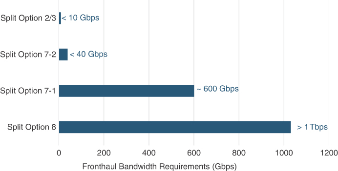
FIGURE 5-17 Example of Required Fronthaul Bandwidth Across Split Options
The introduction of eCPRI helped modernize legacy CPRI transport by utilizing Ethernet and IP for transport as well as lowered the bandwidth requirements between the RU and DU. However, it did nothing to provide open interfaces and interoperability across vendors. While new entrants in the vRAN space were looking to take advantage of virtualization and revolutionize the RAN networks, mobile networks were still subject to vendor lock-in with limited to no interop between RU and DU provided by different RAN vendors. Mobile network operators, wanting to drive interoperability in vRAN, created the Open RAN (O-RAN) Alliance in an effort to collectively influence the industry and speed up the pace of their 5G deployment.
Open RAN
The RAN industry has been dominated by a small number of incumbents, which has shrunk even further through various mergers and acquisitions, resulting in a select few (Huawei, Ericsson, and Nokia) exerting a near-total monopoly on all RAN deployments.47 The evolution to vRAN has created a lot of ambiguity in the industry in choosing the best-suited split options.
Mobile network operators—already vendor-locked with existing RAN architectures and weary of the same restrictions in 5G and vRAN—demanded a multivendor, open, and interoperable RAN ecosystem where they could deploy RU, DU, and CU from any combination of new or incumbent vendors. Incumbents in any industry, especially the ones with large market share, are not only slow to adapt to disruptive changes, they often also resist the calls for openness and interoperability that might lead to loss in their market share. The leading mobile operators, AT&T, SK Telecom, and Deutsche Telekom, along with members of academia from Stanford University, created the xRAN Forum in 2016 with the objective to standardize the components of a software-focused, extensible radio access network. The forum was quickly joined by other industry stalwarts like Telstra, NTT Docomo, Verizon, and vendors such as Samsung, Fujitsu, Intel, Cisco, NEC, Nokia, Radisys, Altiostar, Mavenir, and others. In 2018, the xRAN Forum joined forces with the C-RAN Alliance—which was an effort led by China Mobile and focused on adoption of Centralized RAN architectures. As part of this merger, AT&T, China Telecom, DT, Orange, and NTT Docomo became the founding members of the Open RAN (O-RAN) Alliance, intending to create an intelligent, open, programmable, and virtualized RAN network. The key tenets of the O-RAN Alliance are as follows:48
Use of open and interoperable interfaces, fully virtualized components, and an artificial intelligence–assisted smart RAN network
Minimize proprietary hardware and promote the use of commercial off-the-shelf (COTS) hardware and merchant silicon
Define and drive standardization and subsequent adoption of application programming interfaces (APIs), along with the use of open source software for vRAN deployments
The O-RAN Alliance has quickly grown to include some of the largest mobile operators in the world (Verizon, Jio, Vodafone, Telefonica, and KDDI, to name a few) and over 200 contributors consisting of various equipment vendors and members of the academia. In a very short amount of time, the O-RAN Alliance has had a sizable impact on fostering and nurturing an Open RAN ecosystem through its various workgroups (WGs). A total of 10 workgroups, dubbed WG1 through WG10, have been defined so far, focusing on defining various specifications that collectively make up the O-RAN reference network architecture.49 The O-RAN Alliance uses the baselines defined in the vRAN architecture, and the resulting reference design is often referred to as O-RAN. These specifications defined by the O-RAN design consist of the overall reference architecture as well as components such as the Open Fronthaul interface, RAN controller, orchestration, cloudification, and xHaul transport design—all of which are discussed in this section.
O-RAN Architecture and Use Cases
The O-RAN Alliance was founded on the basic principles of creating an intelligent, smart RAN network by virtue of automation, analytics, machine learning (ML), and artificial intelligence (AI), along with the use of standardized, open interfaces across the various virtualized RAN network components. As such, the overall O-RAN reference architecture uses a multifaceted approach in addition to Open Fronthaul nodes and interfaces. Figure 5-18 provides an overview of the building blocks of the overall O-RAN architecture, and the interfaces between them, as specified by ORAN WG1: Use Cases and Overall Architecture Workgroup.50
As Figure 5-18 illustrates, Open Fronthaul (and its components) is just one part of the overall O-RAN reference architecture, while automation, orchestration, Network Function Virtualization Infrastructure (NFVI) framework, and RAN controller make up the rest of this architectural framework. Different WGs within the O-RAN Alliance define specifications for each of these individual components.

FIGURE 5-18 O-RAN Architectural Framework
Open Fronthaul Nodes and Interfaces
One of O-RAN Alliance’s primary goals is to standardize the LLS option and accelerate the use of open, interoperable fronthaul RAN nodes. With input from both vendors and operators, WG4 (the Open Fronthaul Interfaces Group) defined the use of Split Option 7-2x between the RU and DU for what is known as Open Fronthaul.51 Option 7-2x is another PHY layer split, which should not be confused with 3GPP Option 7-2. It is logically placed between 3GPP Split Options 7-1 and 7-2, and assigns pre-coding, modulation, RF resource element mapping, and other higher-layer functions to the DU and allocates lower-layer functions like analog-to-digital conversion, inverse fast Fourier transform (iFFT), and certain beamforming management functions to the RU. Split Option 7-2x is focused on making it easier to implement the DU functions to run in a virtualized environment using generic COTS hardware. The RUs and DUs that support Open Fronthaul (that is, the O-RAN-compliant implementation of fronthaul through the use of Split Option 7-2x) are called Open RU (O-RU) and Open DU (O-DU), respectively.52
Note
The terminologies O-RU, O-DU, and O-CU signify the use of open, interoperable RAN nodes, where Split Option 7-2x is used between O-RU and O-DU, while Split Option 2 is used between O-DU and O-CU. The O-CU functions can still be further subdivided into O-CU-CP and O-CU-UP, signifying the separation of the control and user planes.
The interface used between the O-RU and O-DU is still called eCPRI, which uses Ethernet or IP encapsulations. However, this 7-2x O-RAN-compliant eCPRI must be distinguished from the eCPRI interface defined by the CPRI forum. The two specifications do share the same naming convention (that is, Evolved or Enhanced CPRI, or eCPRI) and the use of Ethernet for transport, but they differ on the split options used. As mentioned in the previous section, the CPRI forum’s eCPRI implementation allows 3GPP-defined LLS Options 6, 7-1, 7-2, and 8, but mapped to eCPRI’s naming conventions of Option D, ID, IID/IIU, and E. In comparison, O-RAN-compliant eCPRI uses Split Option 7-2x and mandates open interfaces and interoperability between the O-RU and O-DU. Figure 5-19, included in the next section, provides a pictorial mapping of various split options defined by 3GPP, CPRI Forum, and O-RAN Alliance.
In addition to the Open Fronthaul specification through WG4, the O-RAN Alliance also defines open specifications for various other RAN interfaces through WG5 (Open F1/W1/E1/X2/Xn Workgroup), as well as the use of a Fronthaul Gateway (FHGW) through WG7 (Whitebox Working Group). The use of various RAN interfaces was showcased previously in Figure 5-18. More details on Fronthaul Gateway and its applications in the fronthaul transport network are discussed later in the “Transporting Radio Traffic over Packet-Based Fronthaul” section.
RAN Intelligent Controller (RIC)
The past several years have seen a significant increase in the use of software-defined, analytics-driven networks, and the mobile communication networks (MCNs) are no exception. RAN Intelligent Controller (RIC) is the software platform that can be considered the brain of the RAN domain. Using advanced analytics, artificial intelligence (AI), and machine learning (ML), a RIC utilizes the usage data generated in the RAN to provide performance visualization, perform predictive analysis, and create actionable intelligence. These capabilities can then be used to enforce or modify RAN policies to improve resource management, increase RAN efficiency, and optimize overall performance with little to no human interaction. Two different flavors of RIC are defined in an O-RAN architecture: near real-time (near-RT) RIC and non-real-time (non-RT) RIC.
A near-RT RIC interacts with the O-RAN nodes (O-DU and O-CU) and performs near-real-time monitoring and optimization of the radio access network resources. While a near-RT RIC controls the O-DU and O-CU behavior, in reality it acts as an enforcer for the policies defined by the non-RT RIC.
As shown in Figure 5-18 earlier, a non-RT RIC is part of the overall Services Management and Orchestration (SMO) framework, which uses ML/AI and analytics to provide policy guidelines to the near-RT RIC using the A1 interface. A non-RT RIC uses complex algorithms on the usage data and directs near-RT RIC to enforce policies, thus creating an intelligent and smart RAN network.
RIC is not just a single piece of software; it is rather a platform that allows extensibility through hosting third-party apps. Apps hosted on near-RT RIC are called xApps, whereas non-RT RIC apps are referred to as rApps. The use of third-party apps fosters an innovation-based ecosystem using RAN algorithms from various sources instead of being tied only to the software provided by the RIC vendor. Suggested use cases for xApps and rApps include QoS-based resource optimization, mMIMO and beamforming optimization, DSS, dynamic resource allocation for unmanned aerial vehicle, and handover in Vehicle-to-Everything (V2X) scenarios, among others.
RIC is an active area of research and development in the industry and is one of the critical foundations of the O-RAN reference architecture with two working groups (WG2 and WG3) defining non-RT and near-RT RIC specifications. At the time of this writing, there have not been any large-scale production deployments of RIC, but multiple mobile network operators such as AT&T, Deutsche Telekom, KDDI, and China Mobile have publicly commented on production trials for RIC.53, 54
Cloud and Orchestration
Radio access networks have been moving toward a cloud-based architecture for some time. Centralized RAN architecture pioneered the concept of BBU pooling in a central cloud, even though, in most cases, this cloud was an offsite data center hosting specialized BBU hardware. vRAN changes this concept with virtualized RAN nodes (that is, the CU and DU). To ensure that future RAN networks take full advantage of the virtualization, the O-RAN WG6 (the Cloudification and Orchestration Workgroup) provides design guidelines to leverage and drive adoption of generic COTS hardware for virtualized RAN nodes.
Virtualization and cloudification typically go hand in hand, with some virtual functions being moved offsite to an application-hosting facility (that is, a cloud). O-RAN introduces the concept of an O-Cloud, a cloud platform composed of hardware and software components capable of providing RAN functions. An O-RAN-compliant MCN might contain multiple O-Cloud instances, where each instance is a collection of resource pools. These resource pools are essentially servers that contain CPU, memory, storage, network interface cards (NICs), and so on, which can host various individual O-Cloud network functions such as O-DU and O-CU. Given that these O-RAN nodes are typically distributed in multiple locales, a comprehensive automation, orchestration, and management framework is required to ensure consistent and efficient deployment. The Service Management and Orchestration Framework (SMO) defined by WG6 provides a general structure to accomplish just that.55
In order to efficiently operate this distributed, diverse network spread across a vast geography, the use of a robust orchestration and automation framework, such as the one defined by WG6, is vital. While the detailed automation framework is out of scope for this book, the use of automation for 5G transport network deployment and continued operation will be discussed as needed.
O-RAN xHaul Network Architecture
O-RAN WG9 (the Open X-haul Transport Workgroup) has been focused on defining a baseline transport network architecture that encompasses the fronthaul, midhaul, and backhaul domains. As part of this objective, WG9 provides guidance on best practices and design strategies for the xHaul network using two primary transport mechanisms: WDM-based transport for fronthaul and the packet switched transport architectures for fronthaul, midhaul, and backhaul.56, 57 WDM-based fronthaul transport was briefly covered in Chapter 3; however, more details on WDM are out of scope for this book.
The WG9’s xHaul Packet Switched Architecture and Solution Specification outlines various 5G xHaul deployment scenarios, transport network technologies, VPN services implementations, quality of service guidelines, timing and synchronization architectures, as well as other details critical to the transport domain of an MCN. The specification and guidelines put forth by WG9, and the newly formed WG10 (the OAM Workgroup), are useful for data network engineers and architects tasked with designing and deploying a 5G mobile transport network. Later parts of this chapter, and the rest of this book, will exclusively focus on the technologies required to architect these smart, open, scalable, and programmable 5G transport networks.
Summarizing vRAN Split Options and Architecture
While an overwhelming majority of mobile deployments are still D-RAN based, major mobile network operators and vendors are coalescing around the vRAN architecture as the path forward for the mobile industry, given the benefits it provides with respect to resource pooling, efficient RF coordination, cost-effectiveness, and deployment agility. Based on a recent service provider survey, it is estimated that over 70% of the total service providers are planning to switch to vRAN architectures, with just under 50% of them planning to deploy fronthaul networks as well. The rest will use a midhaul-based vRAN architecture where the RRU and DU are collocated at the cell site.58
With the vRAN architecture still in its (relative) infancy, it is understandable that there are multiple standard bodies and organizations defining various BBU split options and deployment choices. Figure 5-19 summarizes the most commonly referenced split option choices.

FIGURE 5-19 Comparing Split Options Across Various Standards
Of all the split options shown, the following are the most commonly used:
3GPP: Option 8 for LTE, Options 7.2 and 2 for dual-split architecture
Vendor-specific eCPRI: Similar to 3GPP with eCPRI names
O-RAN: Options 7-2x and 2 for dual-split architecture, Option 8 for LTE co-existence with 5G
Although O-RAN is relatively new, it has gained significant industry momentum and its reference architecture is expected to become the dominant choice for vRAN deployments. Nonetheless, the dual-split vRAN architecture is quickly becoming the gold standard of mobile network deployment and has widespread implications on the underlying transport design. The underlying xHaul transport not only has to accommodate the transformative dual-split vRAN architectures but may also have to simultaneously support vRAN, Centralized RAN, and D-RAN coexistence in a multigeneration MCN. These implications and their impact on mobile transport network evolution are discussed later in this chapter.
5G Core Network
Similar to previous generations of mobile networks, in the fifth generation of mobile networks, the changes in RAN are accompanied by changes to the mobile core architecture. Although enhancements and incremental changes to the packet core introduced through 3GPP Releases 8 through 13 were generally viewed as extensions to 4G EPC, it’s the concept of Control and User Plane Separation (CUPS), introduced in Release 14, that is widely considered as the first step toward the new mobile core architecture that is now labeled as the 5G Core (5GC) network. Subsequent 3GPP releases further perfected this idea, making it an integral part of 5GC.
Aside from the changes brought through 3GPP specifications, a parallel yet independent transformation of the packet core was taking place in the context of NFV. While NFV and its framework (driven by ETSI) was completely independent of 3GPP’s work, mobile networks (particularly vRAN) were among the initial use cases considered for NFV. As this idea of virtualizing network functions gained popularity among the network service providers, extending these principles to the mobile packet core became a more compelling and promising use case.59 As a consequence, many packet core vendors started to offer NFV-based EPC, dubbed as virtual EPC (vEPC). This virtualization trend continued and accelerated in the transition toward 5GC.
Two key concepts redefined vEPC to become 5GC—namely, Control and User Plane Separation (CUPS), and Service-Based Architecture (SBA), leading to a cloud-native packet core.
Control and User Plane Separation (CUPS)
System Architecture Evolution–related changes in 4G EPC had resulted in separation of the devices that implement the user-plane functionalities (for example, data forwarding) and control-plane responsibilities (for example, session establishment and device registration). Though this separation allowed both user- and control-plane devices to independently scale based on their respective requirements, they were still deployed in the same centralized data centers across the mobile network’s coverage areas. As these data centers were naturally some distance away from the cell sites, the voice and data traffic would incur a small delay while traversing the xHaul networks. While voice traffic is generally handed off to IMS within the same data center, the data traffic experiences additional latency introduced by the PDN/Internet network providing connectivity to the remote servers. The overall latency has been fairly tolerable for the services and applications in the 4G era; it did not, however, meet the requirements and expectations set by URLLC applications that 5G promises to enable.
Aside from latency, the deployments based on the EPC/LTE architecture were also challenged by the soaring bandwidth demands for traffic consumed by and originating from mobile devices. Although the EPC, with its independently scalable control and data planes, could cope with this challenge, this traffic does significantly strain the xHaul networks that had to transport it between the EPC and the cell site. This problem is exacerbated in a backhaul network, with traffic being aggregated from multiple midhauls and fronthauls. As this traffic is expected to increase significantly with 5G, especially with eMBB-type services, the challenge increases multifold. A different approach was therefore needed to remove both these barriers to allow 5G to offer its promised capabilities.
Control and User Plane Separation (CUPS) addresses these challenges and provides a solution by re-architecting the packet core. CUPS finds its roots in the separation of the two planes, which was conceived in SAE/4G and helped with scalability and cost. The proposed solution recognizes that the bulk of the traffic in the mobile networks is user data, which is predominantly sent between the mobile devices and endpoints reachable through the Public Data Network (PDN) interface of the packet core. These endpoints could include content delivery servers, gaming servers, peer-to-peer applications, and so on. Hence, if this PDN connectivity is provided closer to the cell sites, the mobile transport network wouldn’t need to carry the burden of transporting this massive amount of data between the mobile user and the centralized packet core locations. CUPS, therefore, takes the plane separation idea one step further and advocates that instead of co-locating the devices implementing user-plane and control-plane functions, these should be deployed independently—with the user-plane devices deployed much closer to the cell site. PDN connectivity or local servers are also typically implemented along with the user plane, consequently enabling the data communication between the mobile device and remote endpoints without being transported over the entire xHaul network. This architecture, therefore, provides a solution to the transport network’s bandwidth challenge. The latency challenge is addressed by Multi-Access Edge Compute (MEC).
Because control-plane traffic does not require high bandwidth and is relatively less sensitive to latency, the control plane continues to stay at the main data center with CUPS.
Multi-Access Edge Compute (MEC)
CUPS architecture can address the latency challenge by using special-purpose compute resources deployed at the same data centers where the mobile core’s user plane is implemented. These compute resources, called Multi-Access Edge Compute (MEC), can be used to process and locally terminate the time-sensitive traffic. Termination of traffic flows closer to the edge significantly reduces latency compared to transporting this traffic over data networks to remote servers. Therefore, the use of MEC in the CUPS architecture makes it possible to fulfill the goal of 5G URLLC applications.
As data is consumed at the edge locations instead of being sent toward the data network, MEC also offers an additional benefit of fog computing by consuming and analyzing data at a location close to the source. This also benefits mMTC-type applications where IoT-generated traffic is best suited to be processed, analyzed, and reacted upon locally and closer to the data sources.
Although the term coined for the compute resources placed close to the (mobile) network edge was Mobile Edge Compute, in 2017, ETSI decided to give it a more generic name and rebrand it to Multi-Access Edge Compute.60 Even though MEC has gained popularity as a 5G capability, its architecture is defined to be independent of 5G and can be implemented in 4G-based networks as well.61 The placement of MEC is further discussed in the “What’s Hosted at the Data Centers” section.
Placement of the 5GC User Plane
The vRAN architecture benefits by placing the disaggregated RAN components deeper into the mobile network, closer to the 5GC—as much as latency and other constraints allow. Similarly, deploying the 5GC user plane close to the cell sites offers the benefits of reduced latency, especially in the case of MEC and local content delivery network (CDN) servers, and lower bandwidth requirement for the backhaul network. Therefore, a mobile network architect would want to place the 5GC user-plane devices and functions as close to the cell site as possible. That makes the far-edge data center, with a typical distance of 10–20 km from the cell site and boasting a one-way latency of under 150 usec, ideally suited for the 5GC user plane, MEC and CDN server, and PDN connectivity. However, more commonly it’s the edge data center that is the optimal choice instead.
There are two main constraints that limit how close to the mobile network’s periphery the user plane can be deployed:
The packet core functions can’t be placed before the disaggregated RAN components, or more specifically the CU. Placement of the CU will be influenced by the RAN design (with the aim to move it as far away from the edge as possible). Hence, an optimal choice has to be made between the RAN and packet core design to place the O-CU and user-plane 5GC functions; this criterion favors the edge data center as the best choice.
The location that hosts these 5GC devices should also be able to host services or compute, such as MEC, CDN, or peering routers connecting to an Internet service provider or corporate intranet (in the case of Private 5G). Providing these services may not be practical at each far-edge data center due to their smaller serving area, high deployment density, and typically miniature design. Therefore, the edge data centers are once again the preferred choice. In certain cases, it may not be feasible for even edge data centers to meet these requirements, and in such cases traffic is routed to the user-plane functions in the main data center instead.
What’s Hosted at the Data Centers
With the decomposition of RAN and implementation of CUPS for the packet core, the building blocks of mobile networks are now sprinkled across a larger number of data centers spread across the entire MCN. Figure 5-20 represents the composition of these various data centers and the parts of RAN and 5GC that are hosted there.
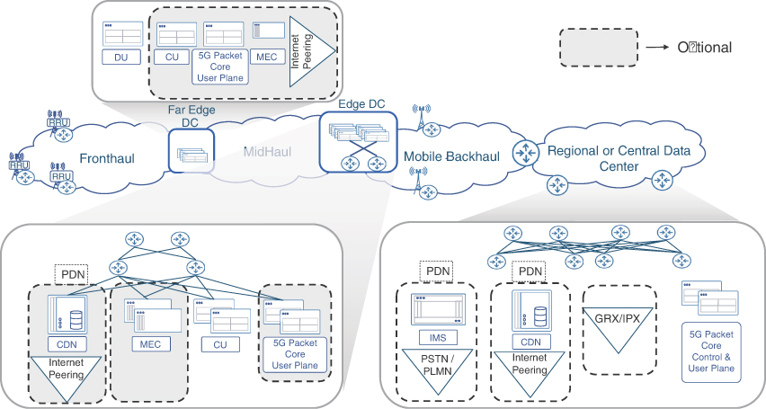
FIGURE 5-20 Composition of the MCN Data Centers
As the figure shows, the devices and functions hosted at the main data center are not much different from EPC—that is, devices implementing the control plane of the mobile network, PDN connectivity to IMS servers (which then connect to PSTN and PLMN), PDN connectivity to reach the Internet (with CDN servers often hosted on the same premises), and connectivity to GRX/IPX exchanges for handling roaming scenarios. Note that even though the data plane is also deployed separately as a result of CUPS, the main DC continues to host data-plane functions. This is meant to handle data traffic that wasn’t offloaded at the edge of the network—either because it wasn’t feasible to do so, the content is latency tolerant, the content is available through the mobile provider’s own servers, or any combination of these. Such data traffic is expected to be only a fraction of the total user traffic and, hence, may not strain the entire xHaul network.
The edge data center, in addition to hosting the CU functionality from the decomposed RAN, will likely also host the 5GC data plane. To send or source this data from the Internet, these edge DCs will also require Internet peering. Additionally, CDN servers can be deployed to reduce the amount of traffic exchanged over this peered network through content caching. Even if Internet peering is not available at an edge DC, CDN servers could still be beneficial. Though MEC is more likely to be hosted at the far-edge data center or even at the cell sites where lower latency can be achieved, it can also be deployed at the edge DC.
The far-edge DC typically hosts only the DU; however, there might be circumstances where it’s required to process or offload the user data even closer than what the edge DC can offer. In that case, the far-edge DC will also host the CU as well as the 5GC user plane and MEC. Examples of such deployment are scenarios where far-edge and edge DCs are collapsed into one location.
Towards a Cloud-Native 5G Core
The application of virtualization techniques and principles of NFV had a major impact on the transformation from EPC to vEPC and subsequently to 5GC. It is therefore meaningful to understand these technologies that facilitate the transition toward a fully virtualized, cloud-native 5G core network.
Virtualization, Containerization, and Docker
In the initial days of server virtualization—to achieve isolation, application security, and resource sharing—hardware-assisted virtualization through a hypervisor was the commonly used implementation. Hypervisor functionality running in a host operating system allows for instantiation of a virtual machine (VM), where a guest operating system (OS) and virtualized applications can independently run. Hence, initial implementations of NFV followed the same model, and the VNFs included an operating system ready to be instantiated as a VM. vEPC followed the same path.
Even though this technique provided great isolation and security, there was a cost to it in the form of slight wastage of hardware resources and longer instantiation time. For deployments where the balance is more toward agility and resource optimization than a high level of isolation, the alternate approach of OS-level virtualization became attractive. This type of virtualization, also referred to as containerization, leverages the capabilities built into the OS to provide some degree of separation, resource sharing, and independence. This segregated environment is referred to as a container.
Compared to VMs, containers have a smaller footprint and make better utilization of the host’s resources while providing a relatively less amount of security and isolation. For example, containers do not require a guest OS, thus making them light on system resource requirements. However, because they share the host’s OS with other containers, they aren’t fully isolated from each other. Most importantly, because containers use built-in OS capabilities, they are free of additional software overhead and resource emulation that would have been required for VMs. This makes containers the preferred choice for dynamic and agile environments.
However, additional capabilities are needed for packaging, porting, maintaining, and managing the containerized applications. Docker is a definite frontrunner among the tools that offer these capabilities and has been the most popular choice. Today, the words Docker and container are used interchangeably, almost completely overlooking the fact that a container is a virtualized application while Docker is an application to package, build, manage, instantiate, version-control, and ship a containerized application.
Microservices Architecture
Virtual machines have their benefits, but they are better suited to a monolithic virtual environment that contains the entire ecosystem of the application. However, the low overhead of containers brings a high level of modularity when virtualizing a set of intertwined applications. The individual applications, or even the individual functions within them, can be containerized. With carefully defined interactions between these applications or functions as well as facilitating these communications through APIs, the containers can easily interact with each other and work cohesively as intended, without knowledge of each other’s inner structure. Thus, each one of these can be independently developed, maintained, spun-up, scaled, upgraded, and patched.
Such an implementation of the software function by breaking it down into individual services-oriented, self-contained, independent, and isolated virtualized building blocks is called a microservices-based implementation. This architecture offers all the benefits of virtualization for each building block (typically a container) that implements a part (service) of the entire application, and through its modularity brings additional benefits such as independent scalability, upgradability, and resiliency of each of these services.
Orchestration and Kubernetes
Managing, orchestrating, instantiating, monitoring, and ensuring the availability of the virtualized functions are best suited for applications designed for these tasks—commonly known as orchestrators.
Management and orchestration (MANO) has always been a critical part of the NFV-based implementation.62 With a microservices-based approach resulting in a high number of individual containers, along with the networking connecting them together, the need for sophisticated orchestrators becomes even more significant. Various orchestrator choices (many of which are open source) have been available for this purpose, but the most popular and predominantly preferred and used choice at the time of this writing is Kubernetes.
Developed originally by Google engineers, Kubernetes is now an open source container orchestration tool. Often abbreviated as Kube or K8s, Kubernetes offers everything that’s expected of an orchestrator. Some of the popular Kubernetes distributions include RedHat’s OpenShift, VMware’s Tanzu, Amazon’s Elastic Kubernetes Service (EKS), Google Kubernetes Engine (GKE), and so on. It’s worth noting that in addition to container orchestration, additional tools and functions may be required to orchestrate and/or automate services and networking. These functions are performed by tools such as Cisco’s Network Services Orchestrator (NSO), RedHat’s Ansible Automation Platform, Juniper Network’s Contrail, and Nokia’s Nuage, among others.
Cloud-Native Applications
A cloud environment, in its simplest form, is any data center that is designed to host applications, provide storage, enable interconnectivity, and offer tools and means to orchestrate, deploy, monitor, and manage these services. This could be a commercially available public cloud (such as AWS, GCP, Azure, and many others), a private cloud (owned and managed on-premises by a corporation), or a combination of the two (called a hybrid cloud). The choice of the cloud environment typically comes down to the cost factor, security considerations, and latency limitations. The capital cost of using a public cloud are very low; however, the operating costs of that might be significantly higher than a privately hosted cloud infrastructure. Cloud platforms have made significant strides in meeting security requirements through the use of sophisticated encryption techniques for storing and transferring data, to an extent that governments are starting to feel comfortable moving their data to the cloud.64, 65 Latency limitations create a requirement of deploying the applications within a certain distance from the users. Deployment of DU is an example of such a restriction, where it has to be within 20 km of the RU. To solve this challenge, most major public cloud providers also offer on-premises versions of their cloud environment, thus extending their cloud to on-premises privately owned locations, while still offering the same orchestration tools and experience as their regular public cloud environment. Some examples of this are AWS Outpost, Azure Stack, and GCP Anthos.
Irrespective of the type of cloud environment, and whether it’s on-premises or publicly hosted, the concept of this ecosystem stays the same. Such an ecosystem with virtualized and containerized applications implemented as a microservices architecture, along with orchestration capabilities, is colloquially referred to as a cloud-native implementation.
Automation capabilities are implied for any cloud-native orchestrator. It’s generally assumed that the containers and their networking in a cloud-native environment have predefined instantiation and deployment templates, lifecycle rules, availability and scalability criteria, and are being actively monitored for failure detection and recovery. The orchestrator is expected to use these and seamlessly run the entire environment with high availability and performance.
Cloud-Native 5G Core
5GC is conceived as a microservices-based architecture ready for cloud-native implementation. The use of Service-Based Architecture (SBA), discussed next, is an essential part to realize this goal. The use of virtualization had already started to remove the dependency on specific vendor hardware, and now the cloud-native nature of 5GC implies that it doesn’t need to be hosted at a data center owned and operated by the mobile provider. Rather, such a cloud-native core could be deployed and run on any type of cloud infrastructure. Of course, the developer of the application or service containers claiming cloud-native capability will need to ensure flawless integration into any cloud environments they are being deployed in and can be managed by the orchestrator and tools being used in that environment.
The 5GC adoption of the industry trend toward open and standards-based APIs means that the individual containers implementing 5GC functions can be from any vendor that the mobile operator finds to be most suitable for that particular service. Hence, 5G Core is ripe to be a multi-vendor, cloud-hosted, highly scalable, and resilient mobile core.
Service-Based Architecture: Decomposition of Packet Core
Mobile core architectures of all the previous generations were designed with a device-centric approach, and, in most cases, multiple functions were implemented on specialized hardware. Even with an NFV-driven transformation of EPC to vEPC, the VNFs, developed to disaggregate from the custom hardware, did not focus on reorganizing the roles and functions implemented by those devices. This was because the device roles were not originally designed for a virtualized environment; hence, vEPC missed out on the full potential of virtualization.
A new approach was therefore needed to reimagine the roles and functions of the packet core, conceived with a virtualization mindset. This new architecture would accomplish the following:
Continue the decoupling effort, by breaking down the functions contained within the virtualized application into separate entities. Reorganize these functions using a cloud-native and microservices approach.
Offer CUPS to separately and dynamically deploy both user and control planes.
Scale and update the relevant functions independently.
Accommodate the needs of 5G-promised services such as low-latency applications.66
Additionally, this approach was expected to facilitate the implementation of new and emerging concepts such as network slicing,67 which was briefly discussed in the previous chapter.
Starting with Release 15, 3GPP developed a new mobile core architecture dubbed Service-Based Architecture (SBA), which draws its inspiration from a combination of microservices architecture and a decades-old software design concept called Service-Oriented Architecture (SOA). While the microservices architecture influenced the repackaging of the VNFs, making them independent, modular, and scalable, its SOA defines how these functions should communicate with each other. SOA defines nodes that offer a service, called service provider or service producer, by registering the services at a service registry. The service consumer nodes then seek and use those services. The beauty of SOA is that each entity, called a function, can be reached by any other through a common communication bus.
SBA defines the 5GC as a collection of loosely coupled, independent, scalable, and microservices-based entities that it calls Network Functions (NFs). The NFs of SBA can be either service consumers, service producers (providers), service registrars, or a combination of these three. Each NF performs a certain role and is able to interface with other functions, while acting as a black box itself (that is, the internal implementation of each function is independent of the others and the interaction between them is only through the exposed interfaces and APIs). 3GPP defined a number of NFs for a very granular implementation of the 5GC, which are discussed next.68
5GC User Plane Network Function
The User Plane Network Function (UPF) is the cornerstone of CUPS and is responsible for the routing and forwarding of mobile user’s traffic to an external network. To achieve low latency, UPF may be placed in the edge or far-edge data centers, in addition to the main DC, as previously discussed in the placement considerations for the 5GC user plane. Additionally, to provide ultra-reliability, either redundant UPF or redundant traffic paths to the same UPF may be used.69
Just like 4G, the 5G packet core also makes use of GTP-U protocol over IP to encapsulate data traffic between the RAN and gateway to the external network, simply referred to as Data Network (DN) in 5G terminology. This GTP-U tunnel is established between the gNB and UPF over the N3 reference interface (thus sometimes referred to as N3 GTP-U). The UPF terminates this GTP-U tunnel and forwards the user traffic to the DN. The UPF (like other cloud-native implementations) is meant to be scalable to meet traffic demands, and multiple UPFs can be spun up when needed.
The mobile device and the UPF use a construct called a protocol data unit session (PDU session) for traffic forwarding. This is similar in concept to the EPS bearer that was defined in 4G networks, but it has some subtle differences—the most important being the granularity of the QoS mechanism. Unlike the EPS bearer, where a single QoS treatment is applied to all traffic, a PDU session can apply different QoS behaviors to individual traffic flows.70
In contrast to the EPS bearer, the PDU session doesn’t carry any signaling information and is composed of a data radio bearer (DRB) between the UE and gNB, coupled with a GTP-U tunnel between the gNB and UPF. The UPF inherits the SGW functionality of anchoring the GTP-U tunnel, and hence when a user moves across the gNB (but within the service area of the UPF), the GTP-U tunnel destination stays unchanged and traffic continues to flow to the same UPF. If the mobile user moves outside of the UPF’s service area, the control-plane functions trigger the procedure to select a new suitable UPF.
5GC Control Plane Network Functions
As of 3GPP Release 17, around 30 control-plane NFs have been currently defined, and this might continue to evolve as 5GC matures further. Some of these functions are optional and are not required in all 5GC implementations. Diving into the detailed description of each of these control plane NFs is beyond the scope of this book; instead, the NFs will be described by logically grouping them together based on their roles. Some studies71 have classified these roles into the nine groups depicted in Figure 5-21.
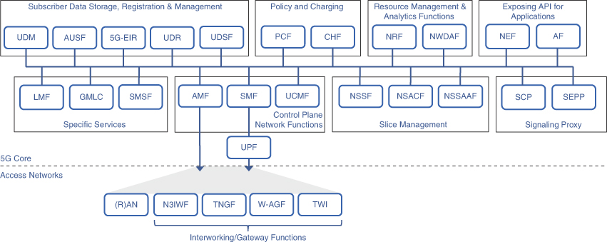
FIGURE 5-21 5GC Network Functions
This section will describe each of these groups, with more emphasis on the groups with higher significance, while only briefly describing the rest.
Primary Control Plane Network Functions
The NFs that form the backbone of the control plane are categorized in this group. As a recap, in an EPC core, the MME and PGW performed most of the control plane functions. The MME would communicate with the eNB and mobile device and would facilitate user registration, mobile device connection management, temporary identity allocation, roaming, SGW/PGW selection, and bearer management. The most important of PGW’s control-plane roles included IP address allocation and policy implementation.
Access and Mobility Management Function (AMF) inherits some of these roles and is meant to terminate all the signaling from the mobile device. The AMF communicates directly with the mobile device, or user equipment (UE) as 3GPP prefers to call it, using an interface called N1, and is responsible for control-plane roles related to the user device (that is, managing the registration process, connectivity, mobility, authentication, authorization, and so on). AMF also has a point-to-point connectivity, referred to as the N2 interface, with the gNB—more specifically with the CU component of the gNB. The N2 interface is used for control plane communications such as PDU session establishment.
Session Management Function (SMF) implements the portion of the control plane that relates to the user’s session. Hence, the bearer management role of the MME is delegated to the SMF. This includes selecting the appropriate User Plane Functions (UPF) for the mobile traffic and then establishing, maintaining, and updating the bearer path between the mobile device and those UPFs. The SMF uses a parameter called Data Network Name (DNN) to select the UPF. The DNN is the 5G equivalent of APN used in previous generation packet cores. Additionally, the PGW’s session management functions also get implemented by the SMF—namely, DHCP and IP address allocation, authorizing a user to access a specific PDN, and providing charging information to the relevant function for billing purposes.
UE radio Capability Management Function (UCMF) is another NF that could be part of this group. The UCMF is meant to store the capability information of the mobile devices, such as vendor information and configuration.
Network Functions for Subscriber Information, Registration, and Management
The registration of a user in EPC relied heavily on Home Subscriber Server (HSS), which consolidated the Home Local Register (HLR) and Authentication Center (AuC) roles. The SBA for 5GC defines two network functions called Authentication Server Function (AUSF) and Unified Data Management (UDM), which implement similar functions.
The AUSF acts as an authentication server, relying on the UDM for subscribers’ identity information (analogous to IMSI). As AMF terminates the mobile device registration request, it uses an interface called N12 to communicate with AUSF for authentication, which in turn uses an N13 interface to communicate with the UDM. SMF also references the UDM for retrieving subscribers’ profiles for the purpose of data session management. The two database network functions, called Unified Data Repository (UDR) and Unstructured Data Storage Function (UDSF), are used by other network functions to store structured data (that is, defined in 3GPP specifications such as subscriber information, policies, and other application data) and unstructured data (that is, not defined in 3GPP specifications), respectively. The UDR and UDSF databases are used by other 5GC network functions, such as the UDM, to access subscriber and policy information as appropriate. Similar to the previous generations, a 5G Equipment Identity Register (5G-EIR) database is optionally maintained to store the device IMEI information to detect devices that are fraudulent, illegal, or not allowed to register for other reasons.
Network Functions for Policy and Charging
EPC’s Policy and Charging Rule Function (PCRF) responsibilities are now delegated to a newly defined Network Function, called the Policy Control Function (PCF). The PCF works with UDM to learn the services a user is allowed to use and then facilitates control-plane functions (such as SMF) to enforce the appropriate policies. Among other things, the policy includes quality of service (QoS) parameters for the user’s traffic streams. Another related function, called the Charging Function (CHF), can be included in this group. The CHF provides an interface to the charging and billing systems.
Network Functions for Exposing 5GC APIs
Two NFs—namely, the Network Exposure Function (NEF) and Application Function (AF)—can be grouped in this category. AF is a generic name for any system inside or outside of the operator network that securely interacts with the PCF or NEF. The NEF provides the actual mechanism and APIs that allow these applications to interact with the other NFs in 5GC.
Resource Management and Analytics Functions
The Network Data Analytics Function (NWDAF) is defined to collect data from various NFs for the purpose of analytics and applying machine learning for optimized resource management. The Network Repository Function (NRF), as the name implies, acts as the service registry and hence a central block of the SBA. Other NFs register with the NRF and advertise the services they provide. When a Network Function requires any of these services (hence acting as a service client), it seeks information about its availability by reaching out to the NRF.
Network Functions for Slicing Management
Three NFs are defined in the 5GC SBA that relate to management, provisioning, and maintaining of network slices—namely, Network Slice Admission Control Function (NSACF), Network Slice Specific Authentication and Authorization Function (NSSAAF), and Network Slice Selection Function (NSSF). NSSF helps select the appropriate slice and resources based on the parameters provided by the mobile user, while NSSAAF helps with authentication and authorization specific to network slicing. NSACF provides slice management, such as limiting the maximum number of devices that may be allowed for a particular network slice.
Network Functions for Signaling
The Service Communication Proxy (SCP) and Secure Edge Protection Proxy (SEPP) are NFs that act as signaling proxies and are defined to help make the SBA implementation distributed and secure. SCP can act as a proxy to other NFs that are registered with NRF and deployed as a single group. SEPP’s proxy role is primarily to make intra-PLMN signaling secure. By using their respective SEPPs to communicate, the mobile providers can ensure authentication, integrity, and security for their signaling message exchanges.
Specific Functions
3GPP defines a category of Specific Functions, which includes functions such as SMS, Location Services, and others. The Network Function responsible for SMS is called Short Message Service Function (SMSF). Two functions are defined to deal with the location and position of the mobile user. The Location Management Function (LMF) gathers this information about the mobile device as well as additional parameters to predict location change, and it exposes this information for the AMF. The Gateway Mobile Location Center (GLMC) provides an interface for external applications and clients to request this information from the 5GC. One example of such applications is law enforcement and emergency services, which may want to know the precise location of a mobile user.
5GC Network Functions’ Interaction with Access Networks
5G doesn’t restrict access to just the RAN. It allows a variety of other access methods, both from trusted and untrusted networks, including Wi-Fi and broadband access. The access network abstraction, referred to as (R)AN by 3GPP, represents the 5G RAN as a single functional piece of the SBA. The use of parentheses in (R)AN indicates that the access network can be a radio network or another type of network, such as a wireline access network. 3GPP also defines interworking and gateway functions, which are meant to adapt the access technology protocols to the 5G control plane. A few mentionable NFs in this category are Non-3GPP InterWorking Function (N3IWF), which offers a user’s mobile device to register with the 5GC using an untrusted Wi-Fi network, and Trusted Non-3GPP Gateway Function (TNGF), which offers gateway functionality when a mobile device connects using a trusted Wi-Fi network. The Wireline Access Gateway Function (W-AGF) is similar in concept to TNGF but defined for wireline access such as broadband cable networks. For mobile devices that don’t support 5GC control-plane signaling protocols and connect using a trusted Wi-Fi network, an interworking function called Trusted WLAN Interworking Function (TWI) has been defined.
Communication Interfaces Between 5GC Network Functions
3GPP defines two different nomenclatures to represent the interfaces between the Network Functions. The first nomenclature, called service-based representation, is defined only for the Control Plane NF. The service-based representation calls out an exposed interface for every NF (for example, Namf for AMF and Nsmf for SMF). These are general-purpose exposed interfaces open for any Control Plane NF to communicate with any other Control Plane NF using the common SBA connectivity bus. The other nomenclature is defined for point-to-point communication between two NFs, similar to the concept of interfaces in previous generations. The point-to-point interfaces were previously called “S” interfaces in the case of EPS, “G” interfaces for GPRS, “I” interfaces for UMTS, and now in 5GC they are defined as “N” interfaces to signify the next generation nature of 5G. For example, the interface between AMF and SMF is called N11; however, it uses the common Namf and Nsmf interfaces of AMF and SMF, respectively, and is often not shown explicitly. Figure 5-22 shows a graphical representation of common 5GC interfaces using both nomenclatures.72
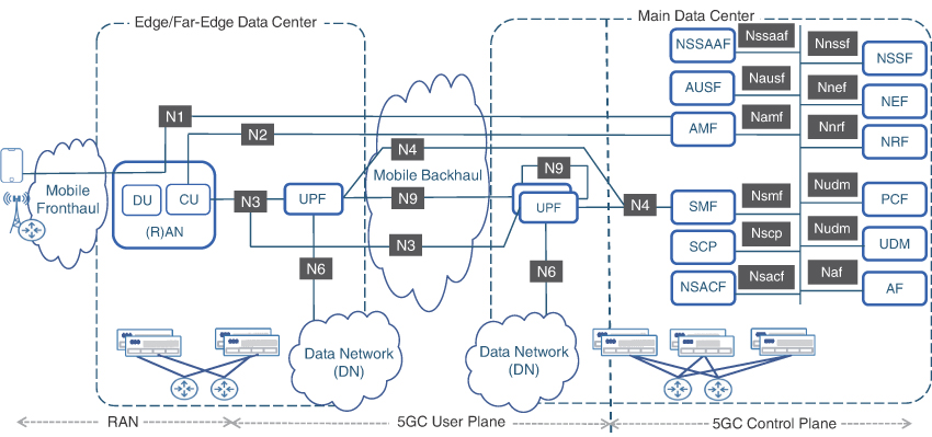
FIGURE 5-22 5GC Communication Interfaces
For the control functions, SBA chose Representational State Transfer API (REST-API)–based messaging for communication between these function, with JavaScript Object Notion (JSON) as the encoding format.73 The reference interfaces related to user plane functions, RAN, and the mobile device use other IP-based protocols such as GTP-U.
User Authentication and Registration
Compared to its predecessors, 5G’s user registration and authentication process is much more secure. The procedure for the initial registration and authentication of the mobile user is similar to that of predecessors, but some well-known vulnerabilities are now addressed. Recall that in 4G, or even before 4G, the mobile device would send the IMSI, which was safely stored in the USIM, to the packet core. Subsequently, the MME would allocate a locally significant temporary identifier, TMSI. However, the initial IMSI value is susceptible to interception by a malicious entity—a vulnerability called IMSI catching.
Instead of IMSI, 5G uses a newly defined identifier called Subscriber Permanent Identifier (SUPI). SUPI is the same as IMSI for the 3GPP-based radio access technologies. For non-3GPP access technologies, where USIM is not being used, the SUPI uses Network Access Identifier (NAI), which is a standards-based method to identify an Internet user.74
Instead of sending the SUPI as cleartext in the initial registration message, the 5G mobile device encrypts a part of the SUPI (the MSIN, to be specific) using the public key of the mobile provider, which is stored on the USIM. The MCC and MNC portions of the SUPI, as well as information about the SUPI type and the encryption method used, are still sent as cleartext since this is already publicly known information. The encrypted identifier, called the Subscriber Concealed Identifier (SUCI), is received by the AMF and decrypted using the mobile service provider’s private key. The AMF works with the AUSF and UDM to authenticate using the decrypted MSIN and set up the relevant services.
Establishing a PDU Session
Once a mobile device is authenticated with the 5GC, it initiates the request (either on its own or triggered by the AMF) to initiate a PDU session. This request, sent to the AMF, includes information such as the location parameters and desired DNN by the mobile device. AMF selects the appropriate SMF, which is then asked to set up the user’s data session. After consulting with the PCF and authorizing the user’s request, the SMF selects an appropriate UPF and, using the N4 interface, programs it with packet-handling information using a protocol called Packet Forwarding Control Protocol (PFCP). In parallel, to establish the end-to-end PDU session, the SMF sends instructions to the CU and mobile device (via the AMF, which then uses its N4 interface to the CU and its N1 interface toward the mobile device). This process also establishes a data radio bearer (DRB) as part of the PDU session.75
QoS in 5G
5G allows QoS parameters to be separately defined for each data flow between the mobile user’s device and the UPF. The QoS parameters are defined as a 5G QoS Identifier (5QI), which is analogous in concept to the QCI used in 4G. The 5QI uses QoS Flow Identifier (QFI) to identify the desired QoS behavior of individual traffic flow and to apply the QoS profile. To draw an analogy with the data networking concepts, this is similar to using DSCP to classify a traffic flow and then using QoS policies to implement the desired traffic treatment. In this example, the QFI is akin to the DSCP marking, whereas 5QI is equivalent to holistic QoS profile that defines the desired behavior of packet delay, error rate, priority, and congestion management.
The initially established PDU session has a default QoS treatment associated with it. Because there can be multiple flows within a single PDU session, these flows, referred to as Service Data Flow (SDF), might not necessarily require separate QoS treatments, and hence the same QFI could be used for all of them—a process called SDF binding. However, if a different QoS behavior is needed for any of the traffic flows, or SDF, then the requirements are requested from the SMF. The SMF authorizes this request by consulting the PCF and allocates a new QFI for the flow, instructs the mobile device to use this QFI for the respective flow, and programs the UPF and RAN to implement the appropriate QoS treatment for this new QFI.
3GPP has defined QoS profiles for the standardized 5QI values, mapping them to specific services. On the transport network, the IP packets are marked with the appropriate value of QoS parameters such as Differentiated Services Code Point (DSCP), experimental bits of MPLS (MPLS-EXP), and so on, based on the 5QI profile for those flows. The transport network QoS policy will then provide the QoS treatment to these packets in accordance with the 5QI profiles defined by 3GPP. Chapter 10 covers this mapping between 5QI and transport network QoS in further detail.
Transition to 5G Core Network
Figure 5-23 summarizes the journey from 3G Mobile Core to 4G Evolved Packet Core and finally the transition to the 5G Core network. The figure shows the correlation between various components of the mobile core across generations, and how these roles have evolved, regrouped, or split into the functions that build the 5GC.

FIGURE 5-23 Transition from EPC to 5GC
5G Transport Network
Irrespective of the mobile generations, transport networks have historically been planned, designed, and deployed with a single purpose—to provide Layer 2 or Layer 3 connectivity from cell sites to the mobile core. However, with the introduction of Centralized RAN and vRAN, previously siloed and distinctly separate RAN and mobile transport domains have become so closely intertwined that it’s unrealistic to draw a clear boundary between the two. The mobile transport has to adapt to provide transport of radio traffic across the fronthaul network as well as support connectivity between RAN nodes and 5GC NFs sprinkled all across the service coverage area in far-edge, edge, and regional DCs. It also has to ensure adequate Internet peering throughout the xHaul to realize the benefits promised by CUPS.
Keeping in mind the overlap between the RAN and transport domains, I implicitly covered many of the aspects of the transport evolution earlier when we discussed topics such as the placement of RAN nodes across the fronthaul, midhaul, and backhaul as well as various DC categories. This section will dig deeper into the evolving role of the underlying packetized xHaul transport network supporting 5G services.
Transporting Radio Traffic over Packet-Based Fronthaul
In a traditional D-RAN architecture, radio traffic is confined to the cell site by virtue of RU and BBU co-location. In this case, the BBU receives radio traffic over the CPRI interface from the RU, performs baseband processing, packetizes the radio traffic, and hands it over to the cell site router (CSR) to be transported over mobile backhaul. The evolution to Centralized-RAN, as well as to RAN decomposition, presented a challenge in terms of transporting CPRI traffic over the fronthaul network. The RAN discussion from earlier in this chapter touched on the introduction of vendor-specific eCPRI and O-RAN-compliant 7-2x-based eCPRI, both of which use Ethernet framing, thus making it possible for a CSR to transport them over a packet-based fronthaul. As eCPRI is a relatively new development, some early 5G RUs and virtually all existing 4G LTE deployments still employ RUs that use CPRI. Radio traffic from these RUs needs to be adapted for transport over the packetized fronthaul using techniques such as Radio over Ethernet or Fronthaul Gateway.
Radio over Ethernet (RoE)
As the name implies, the Radio over Ethernet (RoE) standard, defined by the IEEE 1914.3 specification, describes CPRI transport over a packetized fronthaul using Ethernet. To encapsulate CPRI within Ethernet frames, IEEE RoE standard defines a new Ethertype (0xFC3D), frame format, and introduces the concept of an RoE Mapper and deMapper. Network equipment vendors can implement this RoE Mapper and deMapper functionality on their fronthaul CSR (FH CSR) and the far-edge DC routers to create a bookended solution across a packet-based fronthaul. In this case, the FH-CSR mapper function receives the constant bitrate CPRI traffic, converts it into a packet stream using RoE, and transports over the fronthaul network to the far-edge DC, where the router connected to the DU or BBU re-creates the CPRI stream using the RoE deMapper function, thus enabling RU-to-DU/BBU communication. Traffic from the DU/BBU to the RU follows a similar process.
The IEEE 1914.3 RoE standard defines multiple mapper types for implementation flexibility. Different modes of RoE operations with commonly used mapper types in a packet-based fronthaul are as follows:
RoE Mapper Type 0: This is the structure-agnostic tunneling mode, where CPRI traffic is simply encapsulated within Ethernet frames without any further processing. In this mode of operation, Ethernet traffic rates in the fronthaul mimic those of CPRI rate options. For instance, CPRI Rate Option 7 (9.83 Gbps) would require slightly more than 9.83 Gbps Ethernet bandwidth to accommodate additional bits added by the Ethernet header. Similarly, transportation of CPRI Rate Option 10 over a packet-based fronthaul would require more than 24.4 Gbps of Ethernet bandwidth. Various CPRI rate options are covered earlier in this chapter.
RoE Mapper Type 1: This is the structure-agnostic line-code-aware mode. In this mode of operation, the RoE mapper function removes the line-coding from CPRI traffic. CPRI Rate Options 1 through 7 use 8b/10b line-coding, which puts 10 bits on the wire for every 8 bits of data for redundancy. Stripping 8b/10b line-coding ensures the transport of 8 bits of CPRI over Ethernet instead of encoded 10 bits, saving up to 20% fronthaul bandwidth. CPRI Rate Options 8 through 10, however, use 64b/66b line-coding and hence save only 3% of the bandwidth in the fronthaul (2 bits of Ethernet savings for every 64 bits of CPRI traffic).
RoE Mapper Type 1 is often preferred over Type 0 by network operators due to substantial fronthaul bandwidth savings, especially with CPRI Rate Options 7 and below, but it requires some level of interoperability between network equipment and RRU vendors as the fronthaul transport network element would need to remove and then add back the 8b/10b line-coding on either side of the CPRI connection. This often represents a challenge because RAN equipment vendors may use special characters and messaging between the RU and DU/BBU in their CPRI implementation, thus making RoE Type 1 harder to implement. Both RoE Types 0 and 1 are still CBR in nature.
RoE Mapper Type 2: This is the structure-aware mode where the router implementing this function deconstructs and reconstructs the CPRI stream. Structure-aware mode requires the network equipment vendor to acquire significant knowledge of radio implementation by the RAN equipment vendor, including any proprietary information.
When implemented, however, RoE Type 2 could take advantage of statistical multiplexing of CPRI traffic, allowing the network element (that is, a fronthaul CSR) to receive a constant bitrate CPRI stream, identify useful data (that is, the actual data being sent by the radio or DU/BBU), and convert only this data into Ethernet frames. In essence, this process converts the constant bitrate CPRI stream into variable bitrate Ethernet traffic. This data is converted back into a CBR CPRI stream using a deMapper on the remote end. While highly desired by mobile network operators due to massive amounts of bandwidth savings, the real-life implementation of structure-aware RoE mappers remains scarce because it requires the RAN equipment vendors to open their CPRI stack for the networking equipment vendors to be able to deconstruct and reconstruct the CPRI stream.
RoE represents a significant step toward the adoption of a packet-based fronthaul. However, its usefulness is limited to scenarios where both the RU and DU/BBU use legacy CPRI interfaces. As mentioned earlier, newer radios have started using eCPRI, where the RU and DU both transmit/receive CPRI traffic using Ethernet framing. It must be mentioned that in both these cases—that is, CPRI over RoE and vendor-specific eCPRI—the RU and BBU/DU have to be provided by the same RAN vendor. Interoperability between RAN nodes from different vendors is only possible if O-RU and O-DU are used that adhere to the O-RAN Alliance’s defined Split 7-2x-based eCPRI.
Fronthaul Gateway (FHGW)
With virtualization taking root in mobile network deployments through vRAN, it’s likely to have scenarios where the traditional BBU could be replaced by a CU+DU pairs, where the DU supports eCPRI only, while legacy RUs continue to be used. In those cases, a Fronthaul Gateway (FHGW) could be used to provide conversion between legacy CPRI and eCPRI. FHGW provides an interworking function (IWF) between a traditional RU (which uses CPRI) and a newer DU or vDU that uses eCPRI. This is done through a RAN logic function embedded in the FHGW device, likely to be a cell site router. In essence, the CPRI traffic received from the RU is converted to eCPRI through this RAN processing function and sent to the DU through the uplink interfaces. Similarly, the eCPRI traffic received on the uplink Ethernet interfaces from the DU is converted into CPRI before being sent to the RU. Figure 5-24 shows the FHGW concept as define by the O-RAN Alliance.77
As one can infer, the radio signal processor is an indispensable component of an FHGW, without which the device concept shown in Figure 5-24 is effectively an Ethernet router. Any network equipment vendor looking to implement FHGW functionality on its CSRs must implement this radio signal processor to convert traditional CPRI into eCPRI. It has been previously mentioned that CPRI implementation is proprietary; as such, RAN equipment vendors with a networking equipment portfolio have an inherent advantage in embedding this functionality into their current CSR offerings. Examples of such vendors include Ericsson and Nokia, both of which have an extensive RAN and networking equipment portfolio and have FHGW functionality available on their networking products geared toward 5G xHaul.78, 79 It must be noted that many of these FHGW products provide conversion between traditional CPRI and vendor-specific eCPRI and thus require both the RU and DU from the very same vendor.
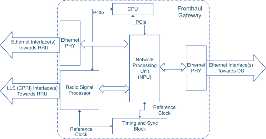
FIGURE 5-24 Fronthaul Gateway Components and Block Diagram
This poses a challenge for networking equipment manufacturers such as Juniper and Cisco that have a limited RAN portfolio and are thus dependent on the RAN equipment manufacturers to implement the radio signal processing functions needed to create an FHGW product offering. As one can expect, incumbent RAN equipment manufacturers, which in many cases are direct or indirect competitors of networking equipment manufacturers, might be reluctant to share their intellectual property (that is, their proprietary CPRI/eCPRI structure) to protect and expand their market share. Networking equipment manufacturers realize this challenge and are working on a two-pronged strategy to carve out a place for their products (such as CSR or aggregation nodes) and protect their market share in this transforming landscape. First, they are working with the O-RAN Alliance to define not only the Open Fronthaul Interfaces (that is, Option 7-2x eCPRI) but also the hardware specifications for an Open Fronthaul Gateway.80 Additionally, the network equipment manufacturers are forging partnerships with new entrants in the RAN market, such as Altiostar (now acquired by Rakuten), to create joint go-to-market strategies and products for 5G networking.81
All of these CPRI adaptation mechanisms are expected to be deployed in mobile networks for CPRI transport over a packetized fronthaul. Figure 5-25 summarizes various scenarios for transporting radio traffic across a packet-based fronthaul network.
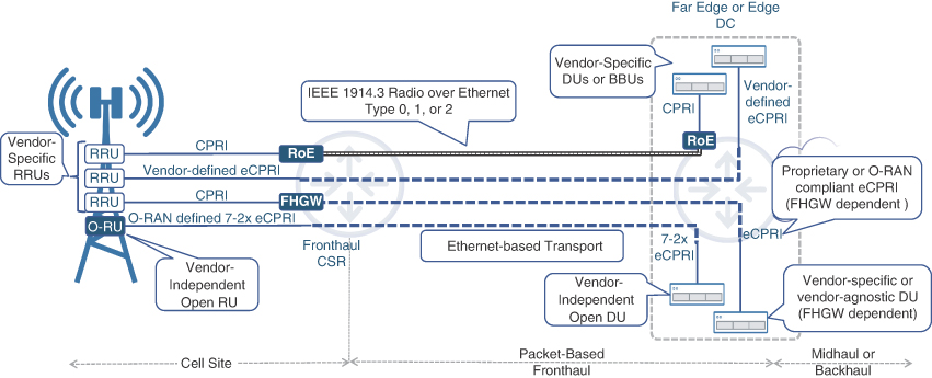
FIGURE 5-25 Transporting Radio Traffic over Packet-based Fronthaul
At the time of this writing, virtually all packet-based fronthaul products use either CPRI over RoE or vendor-specific eCPRI, both of which requires all RAN nodes (RU, DU, CU) to be provided by the same RAN vendor. A handful of new entrants also have O-RU and O-DU available but with limited real-life deployments so far. This is expected to change as mobile network operators demand more openness from RAN vendors and new entrants trying to capture RAN market share from incumbents. FHGW is also a relatively new concept, with the first O-RAN specification defining FHGW being made available in 2021 as part of Working Group 7’s “Hardware Reference Design Specification for Fronthaul Gateway.”82 FHGWs, however, is likely be an interim solution, geared toward the reuse of legacy RUs with newer DUs. Over time, as traditional RUs gradually get upgraded and replaced, the FHGWs will be phased out.
5G xHaul Transport Choices
Chapter 2 previously discussed various transport mechanisms and connectivity models for mobile transport networks such as fiber, cable, DSL, microwave, and satellite. While all of these options can be used in 5G xHaul, additional considerations apply to ensure their feasibility. With midhaul’s bandwidth requirements being substantially lower than fronthaul and somewhat closer to that of a traditional backhaul, all the transport mechanisms discussed earlier could easily be used for both midhaul and backhaul domains. The real challenge lies in the fronthaul, where bandwidth requirements are typically multifold higher than midhaul or backhaul due to the CBR nature of the CPRI transport. Therefore, the bandwidth-restrictive transport mechanisms such as cable, DSL, and satellite, while still viable for midhaul and backhaul, are unfit for a fronthaul environment.83 Fiber optic and microwave are two of the transport mechanisms that can be used for the entire xHaul.
Optical Fiber-Based xHaul Transport
Fiber-based transport networks have long been considered the gold standard of network connectivity due to their flexibility regarding bandwidth capacity, speed, and distances they could cover. While the cost of deployment continues to be a concern, fiber-based transport technologies like WDM, passive optical network (PON), and Ethernet continue to be the leading choices for all xHaul domains, including fronthaul networks.
As mentioned earlier, WDM has already been in use for fronthaul in 4G Centralized RAN deployments and provides ample capacity to meet bandwidth-intensive FH deployment scenarios. Although it’s expected that it will continue to be useful in 5G xHaul, WDM lacks the flexibility offered by packet switched transport networks.
PON is another fiber-based transport technology that has and will continue to provide xHaul connectivity. Lower-bandwidth PON solutions like GPON, NG-PON, and XGPON may be suitable for midhaul and backhaul but may not satisfy the bandwidth requirements for fronthaul. Innovations like NG-PON2 using WDM technology to provide speeds as high as 40 Gbps are needed to fulfill the high-bandwidth requirements of transporting radio traffic over fronthaul. In fact, some network operators already have 5G transport deployed using PON-based technologies.84 The PON ONTs and OLTs are typically equipped with Ethernet Interfaces, which can be used to connect to RU and DU/BBU, respectively, provided the RU and DU/BBU use eCPRI. If the RU and DU/BBU use CPRI, then additional processing will be required to adapt the CPRI traffic to Ethernet for transport over PON based Fronthaul.
Ethernet-based packetized fronthaul, however, is where most of the innovation has been taking place with respect to the 5G transport. The introduction of RoE and eCPRI has made it possible to transport radio traffic using Ethernet, allowing the fronthaul network to benefit from the same features and functionalities as midhaul and backhaul (for example, MPLS VPN, traffic engineering, and rapid restoration). The packet-based xHaul concept, while new and thus limited in adoption at the time of this writing, is expected to grow in the coming years.
The O-RAN “xHaul Packet Switched Architectures and Solutions” specification focuses on the use of packet-based fronthaul, midhaul, and backhaul and documents the use of innovations such as Segment Routing (SR) and Segment Routing v6 (SRv6), both of which are discussed in the next chapter.
Wireless xHaul
As mentioned in Chapter 2, the microwave-based backhaul constitutes a majority of all backhaul links, courtesy of large-scale deployments in developing countries. The unlocking of new and higher frequency bands has opened new possibilities for wireless xHaul. For instance, in addition to microwave allocations in the traditional 6–42 GHz range, more spectrum, particularly in E-Bands (71–86 GHz), W-Bands (75–110 GHz), and D-Bands (110–170 GHz), has been allocated for use for wireless xHaul. Higher frequency band translates into higher capacity, which can provide needed bandwidth for the fronthaul. However, as mentioned in Chapter 2, higher frequencies are best suited for shorter distances.
3GPP has also standardized the use of wireless technology for xHaul transport through the use of the Integrated Access Backhaul (IAB) architecture. In short, IAB allows a RAN node (such as gNB) to act as a donor cell that provides services to mobile users in its coverage area, simultaneously connecting other cell sites to the rest of the network. These IAB-connected cell sites can, in turn, provide services to mobile subscribers in their own coverage zone or act as a donor site for other sites, thus creating a cascading mesh of wirelessly connected cell sites.85 The combination of microwave and IAB technologies allows a mobile operator to mix wired and wireless technologies to create an xHaul deployment suited to its requirements. Figure 5-26 illustrates a sample xHaul deployment using MW, IAB, and wired connectivity.
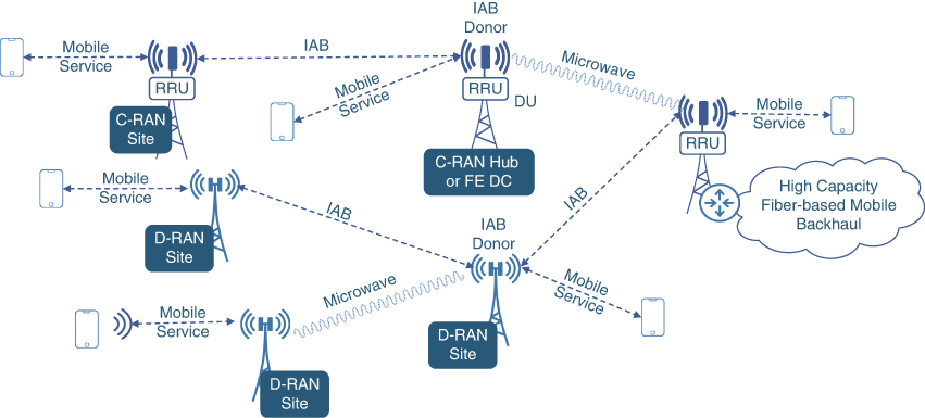
FIGURE 5-26 Wireless xHaul Connectivity Example with Microwave and IAB
Incorporating Data Centers into xHaul
The introduction of new, highly distributed data centers to accommodate the decomposed virtualized RAN and 5GC nodes, and their placement all across the xHaul domain, represent a fundamental paradigm shift in the design and composition of mobile transport networks. Where previously the mobile transport was merely a bridge between the RAN and mobile core domains, now it needs to incorporate DC connectivity in its baseline design—a task that is easier said than done.
Historically, data center and mobile transport networks in large service providers have been designed and maintained by entirely different engineering teams. The technologies used in the both domains are also different, with transport networks using IP and MPLS due to their feature-rich capabilities, whereas a lot of DCs use L2 for fast switching using low-cost hardware. Nonetheless, hundreds of new far-edge DCs as well as dozens of edge DCs need to be incorporated into the xHaul transport, as shown in Figure 5-27.
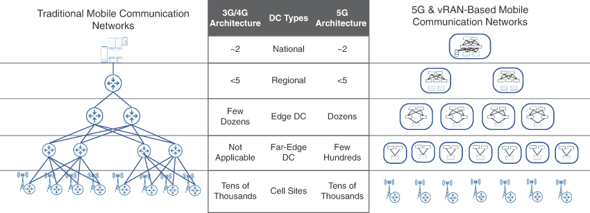
FIGURE 5-27 Data Centers Across the xHaul Transport
Chapter 10 provides details on designing xHaul networks with services spanning multiple layers of DC as well as for RAN nodes and 5GC scattered across multiple DCs.
Distributed Peering Across xHaul
Separation of the control and user planes is one of the defining aspects of the 5G Core, where CUPS allows the placement of additional UPFs closer to the mobile user, typically co-located with the CU in the edge DC. As previously discussed, this reduces bandwidth consumption in the xHaul network and enables low-latency applications.
However, CUPS benefits can only be fully realized if user traffic is also offloaded to the DN as close to the edge as possible. The decomposition of RAN and the placement of RAN nodes, specifically the CU, in edge data centers, where UPF could also be deployed, presents an opportunity to offload user traffic. But in order to do so, Internet peering points that were once limited to a few locations in regional or centralized DCs now need to be made available at many edge DCs, and possibly at far-edge DCs if the CU and UPF are placed there as well. This distributed peering architecture helps xHaul save bandwidth by not having to backhaul user data all the way to the central DC. Figure 5-28 shows a sample deployment of an xHaul network where the mobile network operator offloads its Internet traffic at edge DCs in addition to the central or regional DC.
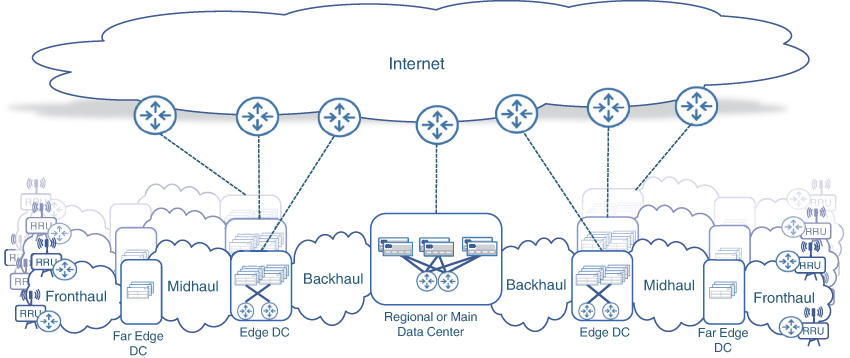
FIGURE 5-28 Distributed Peering for CUPS
Distributed peering is another aspect of new 5G transport networks that has an impact on the xHaul design. The underlying technologies must be able to seamlessly integrate packet transport, data center integration, and data handoff to external peers.
Summary
This chapter covered the technical fundamentals of the three domains of the 5G network: 5G RAN, 5G Core network, and 5G transport. The chapter also shows how the 5G transformations shaping these three domains are going to help the promises of 5G be realized.
For 5G RAN, this chapter discussed the following topics:
Air interface enhancements leading to improved spectrum utilization, communication robustness, and higher speeds
Advanced antenna function for 5G New Radio such as beamforming, massive MIMO, multi-radio connectivity, and dynamic spectrum sharing
RAN decomposition and virtualization of RAN decomposition and virtualization of it components
BBU functional splits, how each split option maps to the 5G protocol stack, and its impact on the transport network
The Open-RAN Alliance and the O-RAN reference architecture
For 5G Core network, the following concepts were covered:
Control Plane and User Plane Separation (CUPS) and its benefits
Placement of the 5G Core user plane
Cloud-native and microservices architectures
Service-Based Architecture and the Network Functions that build the 5G Core
User authentication, session establishment, and QoS
For 5G transport, this chapter went over the following topics:
Overview of Radio over Ethernet (RoE) and Fronthaul Gateway (FHGW) to transport CPRI over packet-based xHaul networks
Transport technology choices for xHaul networks
Integration of the growing number of data centers in the xHaul network
Figure 5-29 captures the full essence of the 5G mobile communication network as explained in this chapter. This figure presents a bird’s-eye view of what the 5G network looks like with CUPS, decomposed RAN, distributed peering, and xHaul transport integrated with data centers.
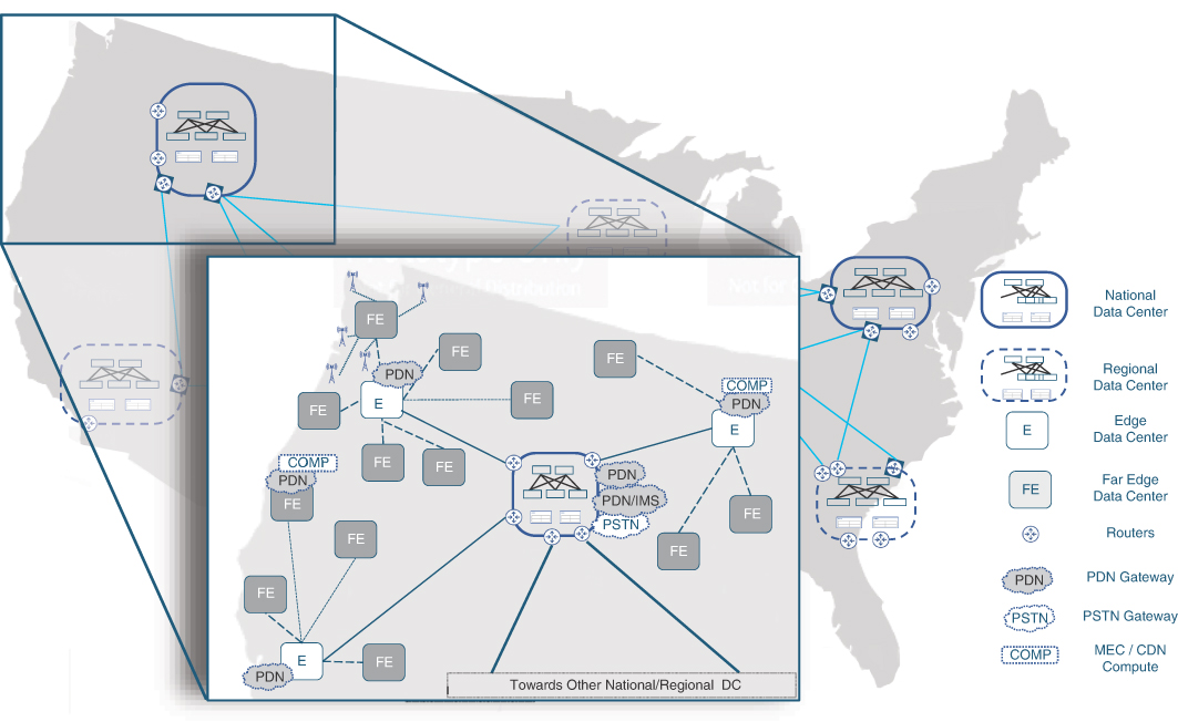
FIGURE 5-29 A Bird’s-Eye View of 5G MCN
The upcoming chapters will exclusively focus on the new capabilities and enhancements for the transport network to enable end-to-end 5G services. These chapters will cover topics such as Segment Routing to build a resilient, programmable transport infrastructure, data center architecture for integration with the transport network, VPN technologies to provide connectivity and services between RAN and 5GCore, the critical concepts of timing and synchronization, and finally a detailed discussion of the considerations and the methodologies to architect transport for 5G MCN.
References
1. 3GPP TS 38.211, “5G; NR; Physical channels and modulation,” Table 4.2-1
2. Op. cit., Table 4.3-1
3. 3GPP TS 38.213, “5G; NR; Physical layer procedures for control”
4. 3GPP TR 38.912-8.1, “5G; Study on New Radio (NR) access technology”
5. 3GPP TS 38.101-1, “5G; NR; User Equipment (UE) radio transmission and reception; Part 1: Range 1 Standalone”
6. 3GPP TS 38.101-2, “5G; NR; User Equipment (UE) radio transmission and reception; Part 2: Range 2 Standalone”
7. 3GPP TS 38.101-1, Loc. cit.
8. 3GPP TS 38.101-2. Loc. cit.
9. 3GPP TS 38.101-1, Loc. cit.
10. Ibid.
11. Ibid.
12. 3GPP TS 38.101-2. Loc. cit.
13. 3GPP TS 36.306, “LTE; Evolved Universal Terrestrial Radio Access (E-UTRA); User Equipment (UE) radio access capabilities, Release 12,” Table 4.1-1
14. Calculated using equation in Section 4.1.2 of 3GPP TS 38.306, “5G; NR; User Equipment (UE) radio access capabilities”
15. 3GPP TR 36.866, “Study on Network-Assisted Interference Cancellation and Suppression (NAIC) for LTE, Release 12”
16. Yuya Saito et al., “Non-Orthogonal Multiple Access (NOMA) for Cellular Future Radio Access,” https://doi.org/10.1109/VTCSpring.2013.6692652
17. Dr. Mohamed Nadder Hamdy, “Beamformers Explained,” https://www.commscope.com/globalassets/digizuite/542044-Beamformer-Explained-WP-114491-EN.pdf (last visited: April 2022)
18. Emil Bjornson, Jakob Hoydis, and Luca Sanguinetti, Massive MIMO Networks: Spectral, Energy, and Hardware Efficiency (New Foundations and Trends, 2017)
19. 3GPP TR 36.819, “Coordinated multi-point operation for LTE physical layer aspects”
20. Siva Muruganathan et al., “On the System-level Performance of Coordinated Multi-point Transmission Schemes in 5G NR Deployment Scenarios,” https://arxiv.org/ftp/arxiv/papers/1906/1906.07252.pdf (last visited: April 2022)
21. 3GPP TS 37.340, “LTE; 5G; NR Multi-connectivity; Overall description; Stage-2”
22. Ibid.
23. 3GPP, “DSS – Dynamic spectrum sharing,” https://www.3gpp.org/dss (last visited: April 2022)
24. “Nokia dynamic spectrum sharing for rapid 5G coverage rollout” (whitepaper), https://onestore.nokia.com/asset/207265 (last visited: March 2022)
25. 3GPP TR 36.786, “Vehicle-to-Everything (V2X) services based on LTE; User Equipment (UE) radio transmission and reception”
26. 3GPP TS 24.587, “5G; Vehicle-to-Everything (V2X) services in 5G System (5GS); Stage 3”
27. “Cellular-V2X Technology Overview,” https://www.qualcomm.com/media/documents/files/c-v2x-technology-overview.pdf (last visited: April 2022)
28. J. Wu, S. Rangan, and H. Zhang Green, Green Communications: Theoretical Fundamentals, Algorithms, and Applications (Boca Raton, FL: CRC Press, 2013), Chapter 11
29. Ibid.
30. R. Chayapathi, S. Hassan, and P. Shah, Network Functions Virtualization (NFV) with a Touch of SDN (Boston: Addison-Wesley, 2017)
31. Gabriel Brown, “New Transport Network Architectures for 5G RAN: A Heavy Reading White Paper for Fujitsu,” https://www.fujitsu.com/us/Images/New-Transport-Network-Architectures-for-5G-RAN.pdf (last visited: March 2022)
32. IEEE 1914.1, “Standard for Packet-based Fronthaul Transport Networks,” https://sagroups.ieee.org/1914/p1914-1/ (last visited: March 2022)
33. Ibid.
34. 3GPP TS 38.401, “NG-RAN (Next Generation RAN) Architecture description, Release 16”
35. Jyrki T. J. Penttinen, 5G Explained. (Hoboken, NJ: Wiley, 2019), Section 6.6.2
36. Sassan Ahmadi, LTE-Advanced: A Practical Systems Approach to Understanding 3GPP LTE Releases 10 and 11 Radio Access Technologies. (Amsterdam: Elsevier, 2014), Chapter 3
37. 3GPP TS 38.300, “5G; NR; Overall description; Stage-2”
38. Ibid.
39. Ibid.
40. 3GPP TR 38.801, “Study on new radio access technology: Radio access architecture and interfaces”
41. Ibid.
42. Ibid.
43. CPRI v 7.0 specification, http://www.cpri.info/downloads/CPRI_v_7_0_2015-10-09.pdf (last visited: March 2022)
44. eCPRI v1.0 specification, http://www.cpri.info/downloads/eCPRI_v_1_0_2017_08_22.pdf (Last visited: March 2022)
45. Ibid.
46. Patrick Marsch et al., 5G System Design: Architectural and functional considerations and long term research (Hoboken, NJ: John Wiley & Sons, 2018)
47. “The RAN market will continue to be controlled by the current three companies, including with OpenRAN,” https://on5g.es/en/the-ran-market-will-continue-to-be-controlled-by-the-current-three-companies-including-with-openran/ (last visited: March 2022)
48. O-RAN Use Cases and Deployment Scenarios, O-RAN Whitepaper, February 2020, https://www.o-ran.org/resources (last visited: March 2022)
49. About O-RAN, https://www.o-ran.org/about (last visited: March 2022)
50. O-RAN Use Cases and Deployment Scenarios, O-RAN Whitepaper, Loc. Cit.
51. O-RAN Fronthaul Control, User and Synchronization Plane Specification, O-RAN WG4, https://www.o-ran.org
52. Ibid.
53. Gabriel Brown, “The Role of the RAN Intelligent Controller in Open RAN Systems,” https://www.stl.tech/white-papers/pdf/STL%20-%20Role%20of%20the%20RAN%20Intelligent%20Controller%20in%20Open%20RAN%20Systems_Final%20WP.pdf (last visited: March 2022)
54. “AT&T and Nokia Accelerate the Deployment of RAN Open Source,” https://about.att.com/story/2019/open_source.html (last visited: April 2022)
55. O-RAN Cloud Architecture and Deployment Scenarios for O-RAN Virtualized RAN, O-RAN WG6, https://www.o-ran.org
56. O-RAN WDM-based Fronthaul Transport, O-RAN WG9, https://www.o-ran.org
57. O-RAN Xhaul Packet Switched Architectures and Solutions, O-RAN WG9, https://www.o-ran.org
58. Sterling Perrin, “Operator Strategies for 5G Transport: 2020 Heavy Reading Survey,” https://www.infinera.com/wp-content/uploads/HR-Operator-Strategies-for-5G-Transport-July-2020_WP.pdf (last visited: March 2022)
59. Craig Matsumoto, “Packet Core Looks ‘Ripe’ for Virtualization,” https://www.lightreading.com/mobile/packet-core/packet-core-looks-ripe-for-virtualization/d/d-id/701518 (last visited: March 2022)
60. The Standard, ETSI Newsletter, Issue 2, 2017, https://www.etsi.org/images/files/ETSInewsletter/etsinewsletter-issue2-2017.pdf (last visited: March 2022)
61. F. Giust et al., “MEC Deployments in 4G and Evolution Towards 5G,” ETSI White Paper, No. 24, February 2018
62. R. Chayapathi, S. Hassan, and P. Shah, Loc. Cit.
63. Craig McLuckie, “From Google to the world: The Kubernetes origin story,” https://cloud.google.com/blog/products/containers-kubernetes/from-google-to-the-world-the-kubernetes-origin-story (last visited: March 2022)
64. Stevan Vidich et al., “Azure Government security,” https://docs.microsoft.com/en-us/azure/azure-government/documentation-government-plan-security (last visited: March 2022)
65. Mark Haranas, “Microsoft Azure Creates Top Secret Government Cloud as JEDI Battle Rages On,” https://www.crn.com/news/cloud/microsoft-azure-creates-top-secret-government-cloud-as-jedi-battle-rages-on (last visited: March 2022)
66. 3GPP TR 23.799, “Study on Architecture for Next Generation System,” Section 4.1
67. Op. cit., Annex B
68. Georg Mayer, “3GPP 5G Core Network Status,” https://www.3gpp.org/ftp/information/presentations/Presentations_2017/webinar-ct-status-11-2017.pdf (last visited: March 2022)
69. Shunsuke Homma et al., “User Plane Protocol and Architectural Analysis on 3GPP 5G System,” https://datatracker.ietf.org/meeting/105/materials/slides-105-dmm-user-plane-protocol-and-architectural-analysis-on-3gpp-5g-system-00 (last visited: March 2022)
70. Andrea Detti, “ Functional Architecture,” https://www.5gitaly.eu/2018/wp-content/uploads/2019/01/5G-Italy-White-eBook-Functional-architecture.pdf (last visited: March 2022)
71. Marvin Ivezic, “Introduction to 5G Core Service-Based Architecture (SBA) Components,” https://5g.security/5g-technology/5g-core-sba-components-architecture/ (last visited: March 2022)
72. 3GPP TS 23.501, “5G; System architecture for the 5G, Release 17,” Sections 4.2.1 and 4.2.3
73. Georg Mayer, Loc. cit. (last visited: March 2022)
74. https://datatracker.ietf.org/doc/html/rfc4282 (last visited: March 2022)
75. 3GPP TS 23.502, “5G; Procedures for the 5G System,” Section 4.3.2
76. 3GPP TS 29.244, “LTE; Interface between the Control Plane and the User Plane nodes”
77. O-RAN Deployment Scenarios and Base Station Classes for White Box Hardware, O-RAN WG7, https://www.o-ran.org
78. https://www.ericsson.com/en/mobile-transport/fronthaul-gateway (last visited: March 2022)
79. https://www.nokia.com/networks/products/airframe-fronthaul-gateway/ (last visited: March 2022)
80. https://blogs.cisco.com/sp/cisco-strengthens-o-ran-market-position-with-open-fronthaul-gateway-public-demo (last visited: March 2022)
81. https://global.rakuten.com/corp/news/press/2021/1026_02.html (last visited: March 2022)
82. O-RAN Deployment Scenarios and Base Station Classes for White Box Hardware, O-RAN WG7, https://www.o-ran.org
83. O-RAN Xhaul Packet Switched Architectures and Solutions, Op. cit., Section 10.2.3.2
84. GSMA Association, “Innovative Fronthaul Network Economics: SKT case study,” November 2018, https://www.gsma.com/futurenetworks/wp-content/uploads/2018/11/SKT_GSMA_Case_Study-v2.1-FINAL-Website.pdf (Last visited: March 2022)
85. 3GPP TS 38.174, “5G; NR; Integrated Access and Backhaul (IAB) radio transmission and reception”