Chapter 10
Designing and Implementing 5G Network Architecture
The last few chapters have gone over network technologies used to build a 5G mobile network. Prior to that, the history and evolution of mobile communication networks (MCNs) were extensively covered. This chapter will merge these topics, focusing on the implementation of the 5G transport network through the application of these essential networking technologies. The chapter will go over various design criteria and architectural considerations that are critical to any such network’s design. It will also touch upon the interpretation of the mobile system requirements that the network needs to support, the selection process for the transport network devices, topology design considerations, and choosing the right features and services.
5G Architecture Recap
Before diving deeper into this design and architecture discussion, it will be helpful to recap key 5G innovations and their influence on the transport network. Here are some of the highlights of the 5G MCN:
5G Mobile Core:
The mobile core in 5G (5GC) is highly granular, with a focus on functions rather than devices. Its cloud-native nature makes it well-suited to be hosted on public cloud environments as well as mobile providers’ private data centers.
5G accelerated the adoption of CUPS for the mobile core, which truly separates the user and control planes, thus allowing the option to move the user plane closer to the network edge. The infrastructure availability, signal flow, peering points, and device placement now have to accommodate this separation of the data plane.
5G RAN:
5G NR features new capabilities such as massive MIMO and beamforming.
The utilization of higher frequency ranges results in smaller coverage zones and hence densification of the radio deployments, thus creating new connectivity challenges.
The use of wider bands offers increased connection speed to end users. Collectively, the denser deployment footprint and faster available speeds directly translate into higher-bandwidth requirement in the transport network.
The decomposition and virtualization of the previously co-located RAN components has resulted in an ongoing architectural transformation toward what is commonly known as a vRAN architecture.
Hosting these RAN functions at far-edge and edge DCs has strong implications for transport network design.
5G Mobile Transport:
This RAN decomposition has also resulted in the evolution from backhaul to xHaul, creating a new market opportunity through the use of midhaul and packetized fronthaul networks.
The choice of lower-layer split (LLS) and higher-layer split (HLS) options has a direct impact on fronthaul and midhaul network designs as well as equipment selection.
The fronthaul network must provide timing and synchronization information to the packetized transport between RU-DU.
The O-RAN architecture and its advocacy toward open interfaces have opened up market segments, which were once dominated by a select number of vendors, to many new entrants.
Figure 10-1 summarizes this 5G MCN architecture as well as the O-RAN-defined planes of operation—that is, control (C-Plane), management (M-plane), user (U-plane), and synchronization (S-Plane). As the figure shows, the pieces of decomposed RAN (RU, DU, and CU) are spread across the xHaul (fronthaul, midhaul, and backhaul) networks. Each one of these xHaul networks has its own constraints when it comes to bandwidth, latency, and device capabilities, which determine their individual design aspects such as the type of devices that can be used and the physical topology. These constraints and design criteria will be discussed in detail later in this chapter. As depicted in the figure, the transport network integrates and provides connectivity for different planes of operations spanning the far-edge, edge, and regional data centers that host the mobile functions. The location, sizing, and even the existence of these DCs depend on the RAN and 5GC deployment model used. The figure also reflects the control and user plane separation of the 5GC as well as the offloading of user traffic closer to the mobile subscriber through distributed peering or processed by MEC applications.

FIGURE 10-1 5G MCN
A parallel yet independent evolution was taking place in the transport technologies that has also shaped mobile communication networks. The development of these new protocols and technologies, such as Segment Routing (SR), Ethernet VPN (EVPN), Software-Defined Networking (SDN), and Network Functions Virtualization (NFV), were fueled primarily by the desire to reduce operational and capital costs, simplify design, achieve deployment agility through automation, and improve efficiency. Although it was not 5G driven, the resulting transport evolution brought by these technologies directly benefits 5G (and even pre-5G) mobile networks, and hence they become essential technologies for building a 5G MCN. A transport network equipped with these (r)evolutionary technologies could now realize the promise of new 5G services. The subsequent sections in this chapter will focus on the design and architecture of the 5G transport network using these technologies.
5G Fronthaul Considerations
The introduction of fronthaul in RAN is perhaps the single most disruptive aspect of next-generation mobile transport networks. Fronthaul was first introduced with Centralized RAN in 4G LTE, but its adoption has been accelerated by the ever-increasing number of 5G deployments.
Decomposed RAN also introduced the concept of a midhaul network to support the HLS option defined by 3GPP. The design requirements of a midhaul are somewhat similar to existing backhaul networks, albeit a bit stricter in terms of latency budgets, and demand higher bandwidths when compared to a traditional backhaul. Network architects, by and large, can draw on their backhaul design experience to create a suitable midhaul network design. Fronthaul networks, on the other hand, require meticulous planning to accommodate the strict requirements resulting from the variety of LLS choices available for the mobile networks. This section aims to highlight various design aspects critical to creating an efficient and functional fronthaul network.
Packetized or WDM Fronthaul Transport?
When Centralized RAN was first introduced, Common Public Radio Interface (CPRI) was a foreign concept for the networking industry. Routers did not support CPRI interfaces and therefore initial fronthaul deployments used wavelength-division multiplexing (WDM)–based optical transport to extend CPRI from cell sites to the C-RAN hub. The use of WDM for CPRI transport might have been necessary in those early fronthaul networks, but with networking equipment vendors starting to implement IEEE’s Radio over Ethernet (RoE) and O-RAN Alliance’s Fronthaul Gateway (FHGW) functions, there are now options to implement a multipurpose, stat-mux-capable, packet-based fronthaul. Additionally, the introduction of evolved CPRI (eCPRI) using O-RAN’s 7-2x or eCPRI Forum’s 7-2 split enables the RUs and DUs to communicate using Ethernet-based transport. The end result in all these scenarios is a packet-based fronthaul that benefits from traditional routing and switching technologies.
As mobile service providers embark on their RAN transformation journey, they will continue to support existing 4G LTE fronthaul networks, simultaneously looking to deploy 5G networks based on LLS Option 8 or Option 7-x. With eCPRI-enabled RUs and DUs, the use of a packetized fronthaul is a no-brainer; however, with LLS Option 8 and for existing WDM-based fronthaul networks, the transport networking team is faced with a simple yet powerful question with far-reaching consequences: should the fronthaul continue to be a special-purpose, exclusive, CPRI-only network, or should it be a general-purpose packetized fronthaul network that could benefit from the flexibility and benefits of an IP-based network? Usually, this choice boils down to the networking team deciding whether to use WDM or a packet-based (Ethernet, PON, and so on) network for fronthaul connectivity between cell sites and the far-edge data center. Both the approaches have their own set of benefits and challenges: WDM offers a simple, easy implementation choice, but is limited in general-purpose usability and management capabilities. On the other hand, packetized CPRI transport offers flexible design, uniform architecture across all xHaul domains, and stat-mux capabilities but requires additional functions such as Radio over Ethernet (RoE) or FHGW, which might not be available on all routers. Also, higher CPRI rate options might not be considered “router friendly” due to their high data rate. For instance, CPRI Rate Option 10 is a 24.33Gbps bitstream, thus mandating the use of 25Gbps, or higher, Ethernet interfaces for the CSR uplink. Current cell site routers typically use 1Gbps interfaces toward the BBU and 10Gbps uplinks. However, newer cell site routers (CSRs) are starting to use 25, 40, and 100Gbps interfaces to accommodate higher bandwidths expected of 5G networks.
Service providers will make this decision based on their own calculus, but Table 10-1 aims to provide network architects with a brief overview of the two contrasting approaches that can be used in fronthaul networks.
TABLE 10-1 WDM vs. Packetized Fronthaul Networks
WDM-based Fronthaul | Packetized Fronthaul | |
|---|---|---|
Fiber Use | Requires P2P dark fiber from each site to hub or requires Add Drop Multiplexer (ADM) at every site to provide rings or daisy-chained topologies. | Inherently supports flexible topologies such as rings and partial mesh. |
Statistical Multiplexing | Has to be designed based on peak capacity required by the cell sites. Further, service is dedicated to the mobile network only, hence no statistical multiplexing. | Statistical multiplexing capabilities are inherent, and the Fronthaul network can be used to carry other services’ traffic, if so desired. |
Redundancy | Optical layer redundancy - typically more expensive to deploy. | Topology based (e.g., rings) as well as protocol based (e.g., fast reroute). |
Operations and Management | Passive WDM (typically used in fronthaul) has no monitoring and remote management capabilities. Active WDM, which is not cost-effective, provides limited monitoring capabilities still not well-suited for automation and operational monitoring. | Data collection, programmability, and automation capabilities are built into virtually all routers, including CSRs, thus facilitating operations and maintenance using existing network management tools. |
Scalability | Dedicated lambdas per site potentially result in inefficient fiber utilization, resulting in increased cost for higher scale. | Stat-mux offers a better utilization of the overall network capacity. |
Optics Flexibility and Maintenance | Use of colored optics presents a challenge, where colors on either end of a CPRI circuit need to match. Any changes in optics have to be implemented on both ends. Spares have to be maintained for every colored optic used. Tunable optics and active WDM could be used to mitigate this, but it drives the costs higher. | Generic gray optics are used at cell sites and pre-aggregation nodes, making maintenance, spares management, and replacement simpler. |
Value-Added Features | Limited applicability and harder to implement due to the dedicated nature of lambdas. | Myriad of IP-based features and functions such as network programmability, transport network slicing support, traffic engineering, and more. |
Cost | Higher total cost of ownership.1 | Cost-effective in most scenarios. |
Technical Expertise | Limited number of trained staff. | Reuse of existing backhaul and IP expertise. |
Table 10-1 clearly shows the technical benefits of the packetized fronthaul over a pure optical-based one. While engineers can be wooed with the technical elegance of a proposed solution, more often than not, the final decision comes down to the total cost of ownership (TCO), including both the capital expense (CAPEX) and operational expense (OPEX) for the proposed solution. Every deployment scenario has its own variables, and research has shown packetized fronthaul to be between 13 and 65% more cost-efficient over various optical-only solutions.2 Nonetheless, network architects must perform a detailed comparison of both the cost and technical capabilities of optical/WDM and packetized fronthaul solutions to choose the best option for their deployment scenario. It is expected that service providers would mix-and-match both the optical and packet-based fronthaul in their network based on fiber availability and preexisting deployments.
Fronthaul Bandwidth Considerations
Bandwidth is one of the two foremost technical considerations (the other one being latency) that dictates much of the design choices for a packetized fronthaul network. The term bandwidth has different meanings for mobility and network architects. Mobility architects use this term to refer to the RF bandwidth (that is, how much frequency spectrum is available). In contrast, for network architects, bandwidth refers to the bitrate of the underlying transport networks. This section refers to the latter definition of bandwidth and the considerations to accurately estimate the fronthaul network’s requirements.
Network bandwidth requirements and estimations for a mobile backhaul network in a traditional D-RAN deployment are fairly straightforward, where the network bandwidth is a function of the number of baseband units (BBUs) at the cell site and the Ethernet bitrate sent from each of the BBU to the CSR. Because all the baseband processing has been performed by the BBU, the network bandwidth requirements are not astronomically high—typically just a few hundred megabits per second from each BBU. This is why virtually all existing BBUs use a 1Gbps Ethernet interface to connect to the CSR. The uplink from the CSR toward the backhaul could either be a 1G or 10G interface, with newer deployments using 10G or higher uplink interfaces for future proofing.
On the other hand, estimating network bandwidth for the fronthaul is neither that simple nor straightforward. As the bulk of baseband processing happens off the cell site, the network bandwidth required from each cell site becomes a function of the RF characteristics, the LLS option used, and the CPRI transport mechanism (that is, RoE for Split Option 8 or eCPRI in case of Split Option 7.x).
There are many RF characteristics that directly impact the network bandwidth utilization in the fronthaul. 5G, as well as some 4G LTE deployments, makes use of wider RF channels that provide a higher data rate to end user, thereby resulting in higher network bandwidth utilization. Additionally, the 5G NR advanced antenna functions seek to maximize the RF bandwidth through features such as mMIMO, beamforming, carrier aggregation, multi-radio transmission, and others. Any effort to extract higher air interface speeds has a direct correlation with bandwidth requirements in the fronthaul network. Thus, the total bandwidth requirement for packetized fronthaul must take into account the following:
The total number of CPRI and eCPRI interfaces from all RUs at the cell site
The individual CPRI rate option used (for LLS Option 8) or the estimated network bandwidth for each eCPRI stream (for LLS Option 7-x)
The choice of packetizing mechanism to transport CPRI over the packet fronthaul network, if LLS Option 8 is used
The total number of CPRI and/or eCPRI interfaces from RUs to the CSR is determined by the number of sectors at the cell site and the number of frequency carriers in each of these sectors. Although the exact number of these interfaces will depend on RF configuration and RAN equipment vendor implementation, a fair estimate of the total number of interfaces is to assume one CPRI or eCPRI interface per carrier per sector for any given cell site. For instance, a cell site with three sectors and four carriers will typically result in a total of 12 CPRI or eCPRI interfaces from RUs to the CSR. The aggregate bandwidth of these 12 interfaces will be the total uplink bandwidth required from the cell site toward the fronthaul network, and will be influenced by the LLS option used.
LLS Option 8, a common split option used in both 4G LTE and some 5G deployments, results in a constant bitrate CPRI stream of uncompressed RF data from each the RUs at the cell site. In this case, the CPRI traffic is an always-on, peak-data-rate bitstream from the RU based on its RF characteristics. Hence, the average data rate for each CPRI interface, in this case, is actually the maximum data rate, which is the derivative of the aforementioned RF characteristics. Unlike other types of network traffic, CPRI traffic cannot be queued, policed, shaped, or otherwise dropped to avoid or manage network congestion. Hence, network architects must plan the fronthaul network to accommodate the cumulative maximum bandwidth from all the CPRI interfaces from all of the cell sites. For Split Option 8, the CPRI packetizing mechanism also plays a role in fronthaul network bandwidth calculations. As previously mentioned in Chapter 5, “5G Fundamentals,” RoE Type 0 (structure-agnostic tunneling mode) actually slightly increases the bandwidth to accommodate Ethernet headers, as CPRI traffic is tunneled using Ethernet frames. On the other hand, RoE Type 1 (structure-agnostic line-code-aware mode) provides up to 20% bandwidth savings due to the 8B10B line-coding being removed and reapplied on CSR and the far-edge DC’s aggregation node in either direction. However, RoE Type 1 might raise interop concerns between the network and the RAN equipment vendor, also previously discussed in Chapter 5. Any service provider looking to use RoE Type 1 must perform extensive interoperability testing between the RAN and networking components of the fronthaul network before production deployment as well as ensure this interop continues across subsequent software releases.
The use of LLS Option 7-x, on the other hand, results in a bandwidth-efficient fronthaul network, as eCPRI allows statistical multiplexing where the bandwidth consumption is based on actual mobile endpoint usage instead of maximum constant bitrate, as is the case with CPRI. With LLS Option 7-x and eCPRI, mobile service providers can plan the fronthaul network bandwidth requirements by analyzing and/or estimating actual network usage. One of the dimensioning principles for fronthaul networks often cited is “one peak and two averages” (that is, in a three-sector cell site, fronthaul network bandwidth can be estimated by using peak bandwidth for one sector and average bandwidth for the remaining two).3
With the introduction of fronthaul networks, almost all RAN and network equipment vendors have developed their own fronthaul bandwidth calculators. Network architects in mobile service providers looking to design 5G fronthaul networks must ask their respective equipment vendors to share estimated bandwidth expectations for each radio antenna and RU based on their specific RF parameters and LLS options.
Impact of Lower-Layer Split on Fronthaul Transport
The choice of LLS option has profound implications on the fronthaul network planning, design, and implementation. As previously discussed, CPRI can either be transported over dedicated fiber links using WDM or sent over packetized fronthaul networks. When using a packet-based fronthaul network, the split option as well as the choice of packetizing technology directly impacts the traffic behaviors, bandwidth needs, as well as the choice of routers to be used at both the cell site and the far-edge data center.
For instance, the use of Split Option 8 requires a specialized CPRI interface on the CSR as well as appropriate packetizing mechanisms such as IEEE 1914.3 RoE or Fronthaul Gateway functionality. The choice of CPRI packetizing mechanism (RoE or FHGW) also defines the network design aspects, such as a two-box bookended solution (that is, RoE mapper and demapper functions) or a one-box CPRI to eCPRI conversion (FHGW). In contrast, Split Options 7-2 and 7-2x both use eCPRI that relies on Ethernet-based framing. Hence, when planning the fronthaul network, the network architecture team must take into consideration the effects of various LLS options, as summarized in Table 10-2.
TABLE 10-2 Lower-Layer Splits and Their Impact on Fronthaul Networks
Lower-Layer Split Option 8 | LLS Option 7-2 | LLS Option 7-2x | |||||
|---|---|---|---|---|---|---|---|
WDM | RoE Type 0 | RoE Type 1 | RoE Type 2 | FHGW | |||
Standardization Body | NA | IEEE | IEEE | IEEE | O-RAN | eCPRI Forum | O-RAN |
Transport Type | WDM | Packet | Packet | Packet | Packet | Packet | Packet |
CSR to RU Interface | Layer 1 | CPRI | CPRI | CPRI | CPRI | Ethernet | Ethernet |
Bookended Solution | N/A | Yes | Yes | Yes | No | N/A | N/A |
CSR CPRI Awareness | N/A | None | Line code aware | Full CPRI aware | Full CPRI aware | N/A | N/A |
RAN-Network Interop Requirement | N/A | PoC Only | Yes | Extensive | Extensive | N/A | N/A |
Bandwidth Saving over CPRI | N/A | None | 20% (rate 1–7) | High | High | High | High |
Stat-mux | No | Limited | Limited | Yes | Yes | Yes | Yes |
Latency Considerations
Another critical aspect of the fronthaul network design is the strict latency budget between the RU and the DU. Latency has not been a pressing concern in traditional mobile backhaul networks because all baseband processing was performed at the cell sites. With geographically separated RU and DU, the baseband processing responsibilities are now divided between the cell site and the far-edge DC. The strict latency requirements between the RU and DU arise from the delicate nature of RF processing, which requires near-real-time communication between the two.
While the RAN equipment (that is, the DU and RU) vendors should provide the exact latency tolerance for their products, 3GPP and the O-RAN Alliance have also defined guidelines for maximum allowed latency between the RU and DU. The latency budget allocated to the transport network is 100 usec or less for most cases.4 In other words, network architects must ensure their network designs and topologies adhere to a one-way latency of less than 100 usec between the DU (possibly located at the far-edge DC) and the RU at the cell site.
Fronthaul network latency is a function of the following:
Physical distance between RU (that is, cell site) and DU (that is, far-edge DC). Every kilometer of fiber adds approximately 4.9 usec of latency.
Transit time for a packet to pass through the CSR and the far-edge DC aggregation router, or WDM equipment in non-packet-based fronthaul.
Number of intermediate routers in the fronthaul topology.
Considering the preceding defined factors, a network architect can estimate the total latency incurred in a given fronthaul network using the following equation:
Total Fronthaul Network Latency = (LF * 4.9) + TCSR + TAgg + (n * TIR)
where:
LF = Length of fiber in kilometers
TCSR = Packet transit time through CSR in usec
TAgg = Packet transit time through far-edge DC aggregation router in usec
n = Number of intermediate routers in the fronthaul network topology
TIR = Packet transit time through the intermediate router in the fronthaul network in usec
Note that the equation calls for calculating the transit time of a packet through the CSR and far-edge DC aggregation router separately from other transit nodes. The reason for this is to accommodate special processing and handling of CPRI traffic at the ingress or egress of these devices, which is different from simply transporting Ethernet frames through a router. The processing required on these devices is based on the LLS option and the features used on the network devices to transport traffic between the RU and DU. For instance, in the case of Split Option 8, the CSR must packetize the CPRI stream using either an RoE mapper or the FHGW function. If RoE is being used, the packetized CPRI traffic must be converted back into CPRI bitstream on the far-edge DC aggregation router using the RoE demapper function. Both the mapper and demapper functions will add extra latency due to the processing performed on the routers. The same is true when using FHGW functionality on the CSR. Although when using FHGW functions, the far-edge DC aggregation router does not require any demapping function because the FHGW performs the CPRI-to-eCPRI conversion. As mentioned in Chapter 5, the FGHW functionality can be vendor-specific (that is, requires RU and DU from the same vendor), or could be implemented as defined by the O-RAN Alliance specifications.5 In this case, the transit time of the packet through the DC aggregation router could be similar to any other transit nodes, as no specialized processing is being performed. Figure 10-2 showcases various scenarios and combinations that could impact latency in a fronthaul transport network.

FIGURE 10-2 Latency Considerations for Various Packetized Fronthaul Transport Scenarios
In order to accurately estimate the fronthaul network latency, the network architects must ask the fronthaul network equipment vendor(s) to provide transit latency data for their products with regard to each scenario shown in Figure 10-2. Transit latency for fronthaul routers is dependent on network vendor implementation. In order to provide the lowest possible latency for CPRI/eCPRI traffic through their routers, many network equipment manufacturers are opting to implement IEEE Time Sensitive Networking (TSN) profiles, on top of existing features and functions necessary for mobile communication networks.6 These TSN profiles are a set of specifications defined by the IEEE TSN technology group focused on providing deterministic services through IEEE 802 networks and establishing guidelines for guaranteed packet transport, low packet loss, and predictable latency, among others. At the time of this writing, the TSN technology group has standardized two profiles, with several others in development. Here are the two TSN profiles that have been standardized:7
802.1BA: Audio/Video Bridging (AVB) Systems
802.1CM: Time-Sensitive Networking for Fronthaul
The other profiles under consideration include TSN for industrial automation, service provider networks, aerospace communications, and automotive in-vehicle communications, among others.
IEEE 802.1CM, “TSN for Fronthaul,” overlaps significantly with 3GPP and O-RAN specifications defining aspects of the fronthaul network, such as the use of different LLS options, CPRI and eCPRI transport over an IEEE 802 network, and the use of PTP for timing and synchronization, among others. Additionally, 802.1CM tackles the issue of low latency and deterministic packet transport for fronthaul networks by defining two sub-profiles:8
IEEE 802.1CM Profile A: Defines prioritization of CPRI IQ data over other fronthaul and non-fronthaul traffic. It also calls for the use of strict priority queuing for fronthaul traffic. Most, if not all, existing routers support QoS features defined in 802.1CM profile A.
IEEE 802.1CM Profile B: Defines the use of 802.1Qbu, “Frame Preemption,” in addition to strict priority queuing. Networking equipment vendors are starting to support Profile B in their fronthaul product offerings.
The TSN specification for 802.1Qbu strives for the highest priority traffic (for example, CPRI or eCPRI) to spend no time in the input or output queues on the fronthaul routers. Whenever possible, network architects should opt for 802.1Qbu-enabled fronthaul routers to ensure that CPRI or eCPRI traffic is promptly processed and forwarded by preempting any non-fronthaul traffic. The resulting latency savings, however miniscule, could allow for slightly more distance between the cell site and the far-edge DC, thus making the far-edge DC placement and selection process a little more flexible.
Selecting a Far-Edge DC Location
A critically important yet sometimes overlooked aspect of fronthaul network design is the selection of a suitable far-edge DC location, sometimes also called a C-RAN hub site. In some cases, the mobile service provider may choose to use an existing cell site, likely to be a macrocell site, as a far-edge DC for its downstream cell sites. In most cases, this makes a lot of sense, as many of these macrocell sites already have the infrastructure necessary to support a small far-edge DC deployment. In other scenarios, it might be more practical to set up a new site for far-edge DC instead of repurposing an existing macrocell location. Whatever the case may be, the following baseline conditions must be met for any location to act as a far-edge DC:
The proposed location must not be more than 20km fiber-length away from its downstream cell sites.
The proposed location must have adequate fiber infrastructure to connect to downstream cell sites as well as to the edge or regional DC.
The proposed location should have sufficient real estate, power, and cooling capacity to accommodate compute and networking equipment required to provide services to its downstream cell sites.
It is important to note that there are no simple and direct answers for a far-edge DC site selection. It is rather a function of technical constraints (such as latency budget limitations between the RU and DU) that defines logistical constraints such as the distance between the far-edge DC and cell site. The physical network topology might also introduce additional latency, as discussed in the previous section, which reduces the 20km distance limitation for fronthaul networks.
Depending on the size of the far-edge DC and the number of cell sites to which it provides services, this location could be a traditional shelter with redundant power supplies, cooling equipment, and racks to mount compute and storage devices for hosting virtualized DUs as well as networking equipment such as aggregation nodes. This could also be a small location without a shelter but a few outdoor cabinets to host a small number of computing devices with built-in storage. Service providers would typically have both these types of far-edge DC sites in their network infrastructure.
If any of the previously defined conditions for a proposed site(s) cannot be met, the mobile service provider should find another site to act as the far-edge DC for its downstream cell sites. If this is not possible, then the provider should consider using a deployment model where the RU and DU are co-located at the cell site.
xHaul Transport Technology Choices
A mobile transport network is only as good as its underlying transport technology, and, as such, the choice of an appropriate transport technology is a key consideration for xHaul design and deployment. Chapter 3, “Mobile Networks Today,” covered a host of technologies that can be used for mobile transport. Traditionally, backhaul networks have used a combination of all the technologies covered in Chapter 3—Ethernet, WDM, PON, cable, DSL, microwave, and, in remote and hard-to-reach places, satellite. All of these technologies are perfectly capable of backhauling mobile traffic, and oftentimes the choice of the transport technology boils down to cost-effectiveness and the service provider’s level of comfort with the chosen option.
Cost-effectiveness is an ever-relevant factor of any viable network design. However, the evolution of a mobile backhaul to mobile xHaul demands reexamining the technical characteristics of a given transport technology to ensure it can fulfill the strict, heretofore unseen requirements of a mobile fronthaul network. Network architects designing 5G xHaul networks must carefully consider the technical attributes of various transport technologies to gauge their suitability for fronthaul, midhaul, and backhaul domains. Every service provider’s deployment scenario is different; therefore, Table 10-3 lists various technical characteristics of transport technologies as well as their suitability for different xHaul domains to help network architects make informed decisions about their xHaul design.
TABLE 10-3 Transport Technologies and Their Applicability to xHaul Domains
Transport Tech | Attributes and Characteristics | Suitable For: | ||||||
|---|---|---|---|---|---|---|---|---|
BW | Latency | Stability | Design Flexibility | Cost | FH | MH | BH | |
Ethernet | High | Depends on the number of nodes and fiber length | High | High | Med | Yes | Yes | Yes |
WDM | High | High | Med | High | Yes | Yes | Yes | |
PON | High1 | High | Med | Med | Possible2 | Yes | Yes | |
DOCSIS | Med1 | High | Med | Med | Limited2 | Yes | Yes | |
DSL | Med1 | Med | Med | Med | Limited2 | Yes | Yes | |
Microwave | Med | Med | Med | High | Low | Limited2 | Yes | Yes |
Satellite | Low | High | Low | Low | Low3 | No | Yes | Yes |
1Dependent on the technology flavor (for example, NGPON offers higher bandwidth than traditional GPON). Similarly, newer flavors of DOCSIS and DSL should be used.
2Topology dependent, as these are shared-access technologies. A higher number of devices on a shared connection could result in inadequate bandwidth for fronthaul needs.
3Excludes the cost of launching satellites into orbit.
Virtually all mobile service providers have built, and will continue to build, xHaul networks that rely on a combination of transport technologies shown in Table 10-3. The exact combination of technologies used will be based on the service provider’s policies, level of expertise, tooling capabilities, preexisting infrastructure, and, of course, the total cost of ownership.
Designing the Mobile Transport Network
Designing a 5G mobile transport network goes well beyond just transport technology choices. The network architecture team must take into consideration a lot of varying factors such as physical network topology, the placement of the RAN and 5GC components as well as their impact on existing mobile networks, end-to-end quality of service, and even the selection of appropriate network devices for a particular role. This section goes beyond just the fronthaul design considerations and aims to take a look at various design aspects for an end-to-end mobile transport network.
Physical Topology Considerations
The topological considerations of a network are often dictated by the choice of underlying transport technology. While technologies like Ethernet allow flexibility and a variety of choices in terms of topological design enabling network architects to build redundancy into their topologies, other technologies such as PON, cable, and DSL offer only the possibility of a point-to-point or point-to-multipoint topology, thus limiting the options available for network design and architecture planning. When multi-access technologies like PON, DSL, and cable are used as the transport underlay for mobile transport, the primary topological consideration is to ensure adequate bandwidth for fronthaul, midhaul, and backhaul deployments by limiting the number of access nodes on the shared topology. Fiber-based mobile transport, however, has the flexibility to deploy different topology options such as rings and point-to-point network fabric.
Ring-based xHaul Networks
Rings have been the topology of choice for most wired networks spanning a large geographical area. They are cost-effective, provide potential for load balancing across multiple paths, and have built-in redundancy mechanisms where traffic could be rerouted in case of link or node failure. Access nodes (or cell site routers in case of an MCN) in a ring topology are generally terminated on a pair of aggregation or pre-aggregation nodes to ensure not only path redundancy but also aggregation node redundancy. Because a fiber ring typically serves a larger geographical area, aggregation node redundancy becomes an important aspect of any ring design since an aggregation node failure has the potential to impact a large number of subscribers. Ring topologies, by far, make the largest number of wired mobile backhaul deployments and will continue to be an important aspect of any xHaul network implementation for 5G transport networks. However, with new requirements regarding latency and bandwidth, network architects must reexamine some of the finer details of a ring-based mobile transport network for their applicability to 5G xHaul networks. One such aspect is the number of devices in a fiber ring and its impact on latency and bandwidth.
Mobile service providers have commonly been connecting up to 10 cell sites, sometimes more, in a single fiber ring. This practice worked pretty well for mobile backhaul, as such a ring would provide connectivity for cell sites over a moderately large geographical area while staying within the maximum latency and bandwidth requirements from all of the cell sites combined. The same practice of roughly 10 cell sites per ring would actually work well with midhaul networks as well. Because the bulk of the baseband processing has already been done at the DU, the latency and bandwidth requirements in a midhaul network are not that drastically different from mobile backhaul. As a reminder, both backhaul and midhaul can tolerate a few milliseconds of latency, which allows for a moderate number of network devices as well as larger distances when compared to fronthaul’s 100-usec one-way latency.
The strict latency and high-bandwidth requirements of a fronthaul network means that network architects must look at the number of devices as well as the distance between those devices in a ring more critically. Every CSR in the ring adds transit latency as well as contributes to the total accumulated bandwidth for the entire ring network. Under normal circumstances, traffic on the ring is balanced across both directions, but given the time-sensitive and lossless nature of the CPRI/eCPRI traffic on the fronthaul, service providers must plan for the worst-case scenario and consider the traffic behavior in case of a failure on the ring. As Figure 10-3 shows, for a 10-node ring, with each cell site 1 km apart and ~10-usec transit latency for each device, the latency requirement of 100 usec from every cell site to the far-edge DC could still be met. However, in case of a failure on the ring, traffic from a cell site would need to take the longer path to the aggregation node. The accumulated transit and path latency could push some sites over the 100-usec threshold, thus creating scenarios where RU–DU communication would become unstable, resulting in loss of service to a large number of mobile subscribers. There is also a potential for congestion if the accumulated bandwidth from all cell sites exceeds the interface capacity of the uplink interfaces on the CSRs.

FIGURE 10-3 Latency Considerations in Ring Topologies
With these restrictions, a lot of service providers are moving to smaller fiber rings (typically five cell sites or less) and lower fiber distances to ensure latency budgets and total bandwidth stay within the required thresholds. In some cases, mobile service providers are also moving toward an Ethernet fabric-based fronthaul network, with direct links from cell sites to the far-edge DC, in order to satisfy the strict bandwidth and latency requirements imposed by lower-layer splits between the RU and DU.
Ethernet Network Fabric for xHaul
Point-to-point hub-and-spoke fiber connectivity has long been the gold standard of a wired network. It offers unparalleled flexibility and potentially unlimited bandwidth, albeit at a higher capital expense resulting from both added equipment (such as additional transceivers and ports on aggregating switches) and the cost of laying fiber over a larger geographical area. However, point-to-point hub-and-spoke network fabrics have been a mainstay of data center networks, offering a repeatable, resilient, and horizontally scalable architecture through a spine-leaf design.
Mobile service providers are warming up to the idea of point-to-point links between cell sites and the far-edge DC, in large part due to the bandwidth and latency limitations imposed by fronthaul networks, although midhaul and backhaul networks may also make use of such a topology. The result is a fabric-like Ethernet xHaul topology that is somewhat similar to a data center fabric, where the leafs are the CSRs and the spines are the pre-aggregation or aggregation routers at the DC sites. There is, however, one notable exception between a DC and xHaul network fabric’s composition: a leaf node in a DC fabric is multihomed to two or more spines, whereas a cell site router in an xHaul network fabric is usually single-homed to one aggregation node. This lack of redundancy can be attributed to the cost of laying multiple fibers from the cell site to the data center. The single-homed connection from the cell site does present a single point of failure for a cell site, where a fiber cut could result in the potential loss of service for all mobile subscribers serviced by that cell site. However, an effective RF design using an overlap of coverage and speed bands can mitigate against complete service failure. Sure enough, some subscribers may face degraded service, but with an umbrella coverage band, the service failure would not be absolute.
The lack of any intermediary transit devices maximizes the distance between cell sites and the DC while ensuring the bandwidth requirements are met for xHaul deployments. The cost of fiber deployment is still a limiting factor, and thus point-to-point fiber links are used between cell sites and the DC only when absolutely necessary. Fronthaul is the primary use case for deploying an Ethernet fabric, rather than a ring network, when possible. The densification of cell sites in 5G, coupled with a potentially large number of far-edge DCs, results in scenarios where fronthaul cell sites might be relatively closer to their respective far-edge DCs. The outcome is a relatively lower cost to run the fiber to an individual cell site, making fabric-based fronthaul networks more feasible. It is expected that mobile transport networks would be composed of both ring and point-to-point topologies in most cases, as shown in Figure 10-4. Other transport mechanisms such as microwave, PON, satellite, and so on would also coexist with fiber-based network topologies.

FIGURE 10-4 Topological Choices in a Wired xHaul Network
vRAN Deployment Scenarios
As has been discussed over the past few chapters, the location of the decomposed RAN components (that is, the RU, DU, and CU) determine the nature of the xHaul network and whether it should be considered a fronthaul, midhaul, or backhaul—each one with its own requirements and design considerations. The potential placement combinations of these RAN functions and the resulting xHaul domains have already been covered in Chapter 5 (refer to Figure 5-12). Nevertheless, mobile service providers looking to deploy a vRAN architecture for 5G must also consider the possibility of a pre-existing 4G or 3G network infrastructure that will continue to coexist with the newer 5G deployments. Many mobile network operators are grappling with adequately defining the use cases and scenarios they will need to support in their next-generation xHaul network. Therefore, network operators in the O-RAN Alliance, in an effort to provide leadership and guidance, documented a few xHaul scenarios pertinent to a typical 5G deployment.9
Figure 10-5 documents several such xHaul scenarios an operator can deploy based on their existing infrastructure and future 5G vRAN plans.

FIGURE 10-5 Commonly Used vRAN and xHaul Deployment Scenarios
As Figure 10-5 illustrates, the packet network connecting the cell site router to the rest of the mobile transport can serve as a fronthaul, midhaul, and/or backhaul simultaneously, depending on the RAN functions used and their respective placements. Network architects must take into account this multipurpose aspect of an xHaul network domain, where a router at the cell site might act as fronthaul CSR for 5G deployment but also as a backhaul CSR for 4G LTE services. In these scenarios, the CSR must be able to provide preferential treatment to the fronthaul traffic, irrespective of which generation RU the traffic might be coming from. The preferential treatment can include priority queuing, guaranteed bandwidth, and the use of TSN-enabled ports to allow frame preemption if available.
The User Plane Function (UPF) moving closer to the subscriber edge is another aspect of designing an efficient xHaul network. Because UPF provides actual connectivity between the subscriber traffic and external data networks, the placement of UPF is heavily dependent on the peering availability at the installation location. While not a function of 5G transformation per se, the evolution and availability of peering points across the xHaul network play a critical role in creating an efficient 5G network.
Peering Considerations
Peering with data networks, such as the Internet or private intranets, has been a pivotal component of any service provider network. The job of a service provider, including mobile service provider, is to connect its subscribers to the content hosted on various data networks. Traditionally, service providers have been limited by the availability of Internet peering exchange locations, forcing them to extend their network presence to those locations. Prior to the widespread use of cloud providers, most of the content was scattered all over numerous smaller networks, and hence robust and diverse connectivity with other networks and transit service providers was of great importance. All consumer traffic and content have to be hauled back and forth from these peering locations (typically on the other end of the service provider network) to the far edges of the network, thereby forcing the buildout of high-capacity IP aggregation and IP core network. The very name mobile backhaul, as mentioned before, was a consequence of this characteristic of hauling traffic from the cell sites all the way to the peering points.
In addition to traditional peering providers such as Equinix expanding their reach, the past several years have also seen the emergence of special-purpose cloud and web providers offering attractive and cost-effective solutions for hosting content, applications, and other resources typically accessed by the subscribers of mobile and traditional service providers. Today, the bigger part of overall Internet traffic originates or terminates in the autonomous systems of these web service providers, such as Amazon, Google, and Microsoft. These cloud and web service providers own some of the largest networks on the planet, spanning multiple countries and continents. Their unprecedented size and reach have afforded them the capability to establish peering points at many locations, sometimes bringing their presence into service providers’ networks. Given the sea-change in the availability of distributed peering locations, mobile service providers now can benefit from these diverse and plentiful peering locations. By establishing distributed peering across multiple locations in their network, mobile service providers can now offload traffic from their network closer to the subscribers. Peering design is considered an essential part of an xHaul architecture and allows the mobile service provider to use public cloud to augment its own network. The use of public cloud for 5G MCN is further discussed later in this chapter.
End-to-End QoS Design
Quality of service (QoS) has been an integral part of any effective network design, and MCNs are no exception. Through QoS, a network administrator can mark certain traffic with a defined priority level through IP precedence or DSCP, MPLS EXP, or class of service (CoS, a.k.a. 802.1P bit). Multiple congestion management and avoidance techniques can then be used to ensure target SLAs are met by preferring high-priority traffic in oversubscribed or congested networks. Some of the QoS mechanisms include ingress policing, shaping, bandwidth guarantee, and priority queuing.
As discussed in Chapter 5, the fundamental difference between 5G and 4G LTE QoS is how it is applied to bearers. While 4G relies on assigning QoS on a per-bearer basis, 5G allows flow classification within bearers and, as such, offers a granular end-to-end QoS mechanism. 3GPP defined a wide list of 5QIs for a range of services such as conversational voice and video, gaming, V2X messaging, non-conversational video, mission-critical data, and signaling, among many others—each with its own intended network characteristics, such as bandwidth guarantee, maximum packet delay budget (that is, latency), acceptable packet loss, and so on. Both the RAN and 5GC domains use 5QI and QFI markers in a flow to offer QoS for different types of services. Generally speaking, the 5QI profiles defined by 3GPP can be classified in two major categories, similar to previous generations:
Guaranteed bitrate (GBR): Flows that require some sort of guaranteed bandwidth. These could either be delay-critical or non-delay-critical GBR flows.
Non-guaranteed bitrate (non-GBR): Flows that do not require any bandwidth guarantee across the MCN.
The 5QI and QFI (as well as QCI for 4G LTE) have great utility in RAN and the mobile core domain, but networking equipment is generally oblivious to these parameters. The routers and switches that make up the transport network rely on IP, MPLS, or Layer 2 (Ethernet/VLAN) based markings to implement QoS. As such, network architects must create a mapping between the 3GPP-defined QoS marking and their transport networking counterpart, which can then be used to define per-hop behaviors (PHBs) for different traffic types. It should be noted that 3GPP defines a plethora of 5QI values—much more than its IP networking counterparts. One way to overcome this imbalance is to group similar types of traffic into a common QoS profile with the same transport networking QoS markings (that is, the same MPLS EXP or 802.1p values for multiple traffic types). These groupings can be based on individual characteristics such as low-latency traffic, traffic that requires guaranteed bandwidth, or traffic that is more flexible on latency and bandwidth. Once the types of traffic are grouped together, the network architecture team can create a complete QoS policy for each different class of service, which includes per-hop behavior like policing, shaping, bandwidth guarantees, maximum time a packet can spend in queue, and whether a packet should be dropped for avoiding or managing congestion. Table 10-4 presents some sample mapping a mobile service provider could use, where groups of traffic from different 5QI values are bundled into a common profile along with their MPLS EXP, IP DSCP, or 802.1P mappings and relevant QoS characteristics. The IP or VLAN-based QoS markings should be imposed by the RU or the 5GC functions when sending traffic to the transport network. It must be stressed that this is a sample QoS profile, and every mobile service provider should look at their own traffic types, network requirements, and service level agreements to create a detailed QoS table.
TABLE 10-4 Sample QoS Schema for MCN
Traffic Class* | 5QI | Transport Markings (CoS/EXP/DSCP) | Forwarding Behavior | BW Allocation *** | Drop Probability | Queue Depth |
|---|---|---|---|---|---|---|
Conversational Voice | 1 | 5/5/46 | Realtime Expedited Forwarding (that is, Priority Queuing) | 50 | None | 5 msec |
Conversational Video (Live) | 2 | |||||
Real-time Gaming | 3 | |||||
Non-real-time Video | 4 | 4/4/36 | Assured Forwarding | 40 | None | 20 msec |
OAM | — | 4/4/10 | ||||
IMS Signaling | 5 | 6/6/32 | Assured Forwarding | 5 | None | 50 msec |
Network Control | — | 6/6/48 | ||||
Data High Priority | 6 | 2/2/18 | Assured Forwarding** | 55 | Low | 50 msec |
Non GBR Video | 7 | 2/2/20 | Med | 50 msec | ||
Data Reg Priority | 8 | 2/2/22 | High | 50 msec | ||
Data Low Priority | 9 | 2/2/14 | High | 50 msec | ||
Data – Scavenger | — | 0/0/0 | Best Effort | 0 | High | 50 msec |
* Not all traffic classes shown.
** Classified as non-GBR by 3GPP. Service providers can use oversubscription on these traffic types.
*** Total bandwidth exceeds 100% since Priority Queue bandwidth is not counted in the total, as it can take bandwidth away from other classes when needed. Non-PQ classes add up to 100% of the remaining bandwidth after PQ requirements are met.
Selecting the Right Network Device
Mobile communication networks are generally spread over larger graphical areas spanning entire cities, states, provinces, or, in a lot of cases, entire countries. Needless to say, the underlying transport network that supports these MCNs also spans hundreds or, in some cases, thousands of kilometers. Networks as large and diverse as mobile transport require appropriate network devices at every layer of their infrastructure. The choice of these devices is guided by many different factors, such as their intended role in the network, the location in which they will be placed, the scale they need to support, and obviously the features and functions they need to perform. This section aims to highlight some key factors that network architecture teams must consider when selecting devices for mobile transport networks.
Environmental and Placement Considerations
Routers for mobile networks come in various shapes and sizes depending on their intended placement and function. IP aggregation and core devices are usually placed in well-developed structures such as a point of presence, a local DC, or a regional DC. These devices can also be larger in size, sometimes half a rack size or more. Due to the number of subscribers served by an aggregation or core node, these devices should also have built-in redundancy to ensure a single failure does not bring down the whole router. The typically larger size provides ample space for multiple control modules (sometimes called route processors or route engines), power supplies, fan trays, and, of course, dozens, if not hundreds, of high-speed interfaces. Given that these large routers are usually placed in well-built structures with controlled environments, they are not required to be environmentally hardened to the extent where they need to withstand extreme temperatures and outdoor conditions.
For access nodes, such as CSRs, their size and environmental tolerance are important consideration factors for any deployment planning. While each deployment is different, CSRs are expected to be placed in one of the three types of locations typical of a vast majority of cell sites. First is a cell site with a well-built shelter, right at the cell site or a short distance away, with ample space for power and cooling equipment as well as potentially space for multiple racks where the CSR and other equipment can be mounted. This type of location could also act as a far-edge DC for downstream cell sites. Another common deployment location is a cell tower with a few cabinets at the base of the tower that provide some degree of protection from the environment but is constrained in the space available for the CSR and other equipment. The last one is a new but growing trend, where 5G cellular antennas are mounted on a standalone pole or street light, with limited or no space underneath.11, 12 Figure 10-6 shows examples of each of these cell site deployment types.

FIGURE 10-6 Environmental Protection at Cell Sites
The CSRs must be able to accommodate the requirements for the type of cell site they are being deployed at. In cases where the CSR will be installed in the cabinet or a rack in the shelter, environmental requirements are somewhat relaxed, but the CSR must meet the physical size requirements to fit in the cabinet or shelf. Service providers prefer the CSR to be a compact device, able to fit the 19-inch-wide rack commonly used at the cell sites, rather than the 21-inch ETSI racks that are more common in point-of-presence and central DCs. The CSR is also preferred to be 1 rack unit in height. A rack unit is a measure of the regions a rack is divided into. Depending on the height, a typical 19-inch rack may have up to 45 rack units, with each one about 1.75 inches in height. A 1-rack-unit CSR leaves a lot of space on the rack that could be used to mount other equipment such as BBUs in D-RAN deployments or DUs in case of a decomposed vRAN design with co-located RU and DUs. By comparison, the aggregation or IP core routers can span multiple rack units, some as high as 18 or 20 rack units or more.
The growing popularity of small cells with street lights being turned into cell towers and antennas being mounted on standalone poles adds another set of constraints for the CSR placement. In these cases, the overall dimensions as well as environmental hardiness become key selection criteria for an appropriate CSR. If the router is to be installed directly on the antenna post out in the open, it must be compact in size and must be appropriately weatherproofed. A vast majority of these deployments require the CSR to adhere to relevant ingress protection (IP) ratings, such as IP65, which protects the complying node from dust and low-pressure water jets such as rain.13 Another important aspect of an outdoor-capable CSR is its size and weight. As seen in Figure 10-6, some of the newer cell towers might be deployed with a net-zero ground footprint, which means that all the equipment, including the CSR, has to be placed within an enclosure in the streetlamp or mounted on the pole. Hiding the equipment in such an enclosure or placing it several feet above the ground also reduces the chances of vandalism. Bulkier gear might not fit in the limited space on the street light enclosure, and a heavier CSR that needs to be pole-mounted might require additional consideration such as aerial lifts and teams of people to install such a device, thereby increasing the costs and timelines of deployment. Limiting the size and weight of the outdoor CSR can allow a mobile service provider to expedite the cell site rollout at a lower cost.
In many cases, the size and weight of a router are considered table stakes to determine whether a device could act as a CSR for a given 5G deployment. Once a proposed CSR meets the guidelines of dimensions and environmental hardiness, network architects must closely examine the features supported, or planned to be supported in the near future. The availability of software and hardware features is equally as important as environmental factors, if not more so.
Timing and Synchronization Support
The previous chapter covered the importance of timing and synchronization in a fronthaul network. The devices used in these 4G or 5G fronthaul networks (the CSR and far-edge DC aggregation nodes) must support time of day as well as phase and frequency acquisition and distribution. In other words, the fronthaul routers must support PTP, SyncE, and NTP.
To ensure the highest degree of accuracy and precision in distributing timing and synchronization information through the fronthaul network, it is highly recommended to use a Class-C or higher PTP device where possible. As mentioned in the previous chapter, the accuracy ratings of a PTP device (that is, Class A, Class B, Class C, or Class D) are a function of device’s hardware components rather than software implementation, and, as such, the decision to use fronthaul devices that support appropriate timing and synchronization functions must be made at the time of deployment. Certain value-added features and software functions (usually vendor implementation specific) could be added to the device’s operating system at a later time, but failure to appropriately select a Class C or higher device at the onset of network deployment could lead to costly forklift-upgrades in the future if timing accuracy and precision between the RU and DU become a problem.
Additionally, when possible, fronthaul networks should be designed using the G.8275-1 Telecom Profile, where every router acts as a boundary clock (BC), thus ensuring the highest level of accuracy when distributing timing information. This means that all devices in the fronthaul network (even intermediary ones) must support the PTP BC functions. Today, virtually all routers designed for 5G mobile transport networks support PTP BC functionality.
Other deployment profiles such as G.8275-2 and Assisted Partial Timing Support (APTS) could still be used if any intermediary devices do not support BC functionality. These scenarios are more prevalent in cases where preexisting network devices not capable of timing distribution are used to carry fronthaul traffic. However, the use of these devices can add to the inaccuracies in timing distribution, thus causing potential connectivity issues down the line.
Supported Interface Types
5G is promising exponential bandwidth growth with the unlocking of new, higher-capacity RF spectrum and advanced antenna features such as mMIMO, multi-radio transmissions, and beamforming. Many of the cell sites are expected to be multiple radio access technologies (multi-RAT); that is, in addition to the new 5G services and traffic, they would continue to support earlier services and traffic from earlier cellular generations.
All this translates into higher bandwidth demands on the network, and the network architecture team must ensure there are enough 100Gbps interfaces, or even 400Gbps interfaces, to provide adequate capacity for new and existing cellular service. Fronthaul is an especially bandwidth-hungry xHaul domain, where the use of LLS options, particularly Option 8, further exacerbates the need for higher-bandwidth interfaces. As previously mentioned, network architects must work with the RAN team to determine the total capacity required at every cell site and determine appropriate interfaces. The network topology (for example, Ethernet rings or a wired cell site aggregating multiple microwave cell sites) also plays a role in choosing the appropriate interfaces.
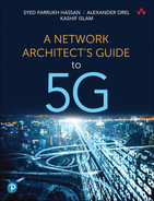
Bandwidth and higher capacity interfaces are not the only considerations a sound network design needs to take into account, however. At every cell site, the RAN components connect to a CSR. This connection between the RAN and the CSR have traditionally been an Ethernet link, but the use of an LLS option in a decomposed RAN environment adds a degree of variability to this long-standing practice. If the LLS option results in an eCPRI (typically Option 7-2 or 7-2x) from the RU, this link between the RU and DU could continue to be an Ethernet link. But if LLS Option 8 is used, the connection between the RU and CSR will be CPRI, and the CSR must be able to terminate the CPRI link. Hence, a fronthaul CSR, expected to be deployed in a scenario where Split Option 8 is used, must have CPRI port(s) to terminate the connection from a Split Option 8 RU. As previously mentioned, this CSR would then implement RoE or FHGW functions to transport packetized CPRI traffic over the fronthaul network. When using RoE, the far-edge DC aggregation node should reciprocate this setup by accepting the packetized CPRI traffic from the fronthaul, convert it back to CPRI, and send it to the DU (or the BBU). Therefore, the far-edge DC aggregation node, in this case, not only needs to have CPRI ports to connect to the DUs, but must also ensure it has the port density required to connect all the DUs required to serve the cell sites. This is a fronthaul-only consideration, and only when Split Option 8 is used. Midhaul and backhaul CSRs and aggregation nodes require only Ethernet interfaces.
Figure 10-7 provides a decision tree to help network architects understand the types of interfaces required on a CSR based on their xHaul placement and LLS option used. Networking equipment vendors are starting to provide both CPRI and Ethernet interfaces in their newer fronthaul CSR and FE DC aggregation node offerings. Although this type of deployment is expected to be fairly limited—either 4G LTE Centralized RAN or 5G RUs with Split Option 8—it is absolutely critical that xHaul networking design take this niche requirement into consideration if needed.
FIGURE 10-7 Selecting the Right Interface on CSR
Planning for Scale
At the time of this writing, 5G deployments are still in their infancy, and yet every indication is that 5G isn’t going to be anything like its predecessors as far as the scale is concerned. Whether it’s cell site densification, higher bandwidth requirements for eMBB, the use of multi-access edge compute (MEC), or an increase in the number of devices connected to the Internet through mMTC services, the growth of cellular networks and the devices served by them is expected to be exponential. Network architects must ensure that the underlying transport networks responsible for carrying 5G traffic for all these multiple traffic types can scale to match the 5G growth expectations.
Network scalability is essentially a function of ensuring appropriate scale at every level of the network—the CSR, the core and aggregation nodes, as well as the use of a scalable architecture to stitch all xHaul domains together. There are many dimensions to a network’s scale, focusing on things like routing table scale to accommodate higher number of devices, port density, software resources such as VPN instances, MPLS label space, access control lists, and other miscellaneous features and functions.
As the mobile networks continue to grow in size through cell site densification and addition of new xHaul domains (midhaul and fronthaul), routing scalability both from an architecture standpoint and from an individual device’s standpoint becomes an important characteristic of a sound network design. Routing architecture scaling can be achieved through Seamless MPLS and BGP Labeled Unicast (BGP-LU), previously discussed in Chapter 3, where network architects can optimize and scale the routing design by ensuring that only the host routes are advertised into BGP-LU and imported across discrete routing domains as needed. Routing design scaling and simplification mechanisms are also discussed later in this chapter, but network device selection for an MCN must ensure the nodes chosen for various roles are capable of the routing table scale required in a large network.
Some of the major roles a network device plays in a 5G MCN are cell site router, pre-aggregation or aggregation node at the far-edge or edge DC, IP core router, data center interconnect, and peering router, among others. As mentioned in the previous section, most of the routers in an MCN, with the exception of the CSR, are typically larger devices that should have adequate resources to handle the required scale. Appropriate architectural decisions are critical to ensure that CSRs maintain the delicate balance of low cost yet a functional end-to-end design. Some of these scale and network simplification techniques to allow this are discussed in the sections that follow.
Adequate Feature Richness
The networking landscape is undergoing rapid changes. Its traditional role is undergoing an unprecedented disruption after the introduction of software-defined networking and increasingly intelligent applications that demand visibility deep into the network. Networking devices today must support a multitude of software features and functions to provide a level of network abstraction that enables higher-layer application to not only interact with but also control the network. Notably, these features are not entirely related to MCN but are essential in supporting various transformative aspects of next-generation networks such as orchestration and closed-loop automation.
Network architects must be cognizant of the holistic direction the networking industry in general, and their organization in particular, is heading toward with regard to automation, network programmability, orchestration, and other transformations. For example, if one of the goals is to move toward a software-defined transport allowing applications like Path Computation Element (PCE) to control traffic flows, the router should support appropriate protocols such as the Path Computation Element Communication Protocol (PCEP) for external applications to dictate the traffic path based on a certain set of constraints defined by said application. Another example could be the use of automated orchestration, where routers should support APIs to allow external applications to connect to and make desired configuration changes. The network devices might also be required to provide an adequate level of visibility into operations and events. As such, they should support features like telemetry in lieu of, or in addition to, traditional SNMP and syslog support. It’s important to note that a lot of these features and functions are not directly related to fundamental operations of an MCN, but these value-added features are becoming increasingly important to simplify network operations and enable mobile service providers to operate networks at an unprecedented scale.
Routing Design Simplification
While 5G itself is complex, the routing in the transport network should not be. The 5G mobile communication network’s comprehensive improvements are tightly coupled with the new level of decentralization and decomposition of its previously monolithic parts. The flip side of the flexibility and power of decentralized MCN is its complexity and strong dependence on highly sophisticated transport networks, especially with introduction of new domains. Traffic patterns and communication flows in 5G MCN are even more intricate and demanding. The routing design simplification becomes paramount to ensure the 5G transport network does not become too complicated to operate.
Chapter 3 covered some of the complexities of mobile backhaul and core networks. A large number of cell sites, common in MCNs, do not align well with cost-efficiency requirements for individual CSRs to support simple network designs. The network designers are forced to split xHaul networks into numerous smaller routing domains to stay within typical CSR scale constraints. Without redistribution of routes between domains, which causes scalability challenges on CSRs, it is not easy to maintain an end-to-end label switched path (LSP). The use of BGP labeled unicast solves the problem of providing MPLS LSP, but it poses many questions such as what to do with next-hop path attributes, where to put route reflectors, and how to keep the number of BGP-LU routes under control. BGP-LU-based designs, standardized as Seamless MPLS, have become the de facto standard in mobile transport networks. Nevertheless, it is notoriously complex and operationally expensive.
Segment Routing brings a new set of tools to enable end-to-end services over mobile transport network. In order to take advantage of cost-effective platforms at the cell sites, xHaul networks continue to rely on multiple IGP domains. At the same time, SR features, such as Segment Routing Traffic Engineering and On-Demand Next Hop, allow mobile service providers to ditch BGP-LU designs in favor of simpler and cleaner SR-enabled transport networks, while offering the necessary MPLS LSPs to establish services over multidomain xHaul networks. This section discusses some of the techniques used to simplify routing in mobile transport network.
Designing Multidomain IGP for 5G Transport
Radio densification and larger coverage areas of 5G MCN significantly increase the number of nodes in transport networks, compared to the previous generation of mobile networks. The question is not if the network should be segmented into multiple IGP domains but rather how big those domains should be and where to place domain boundaries. The main driver for introducing IGP domains is the desire to contain number of routes on CSRs. Many architects use a rule of thumb to limit the number of CSRs in a single domain below a few hundred or even a few dozen. Although it is not uncommon to have thousands of nodes per IGP domain in SP networks, the SPF recalculation churn can put a significant strain on a cost-effective CSR and is therefore not ideal.
Naturally, the most direct approach in defining IGP domain boundaries is to use the network’s topological features. For instance, in ring-based topologies, the nodes aggregating multiple CSR rings can become domain border routers and divide the network into separate domains. With fabric-like topologies, splitting the network into routing domains can be less straightforward. In this case, one possible approach is to select clusters of cell sites residing next to each other and expect to have a significant number of handoffs. Ideally, CSRs in such cell sites should be connected to the same aggregation nodes so they can participate in the same IGP domain. This principle of natural boundaries applies to both D-RAN and Centralized RAN deployment scenarios. In fact, the hard distance limitations of RU-DU communications create another potential for IGP domain separation in fronthaul networks. With no communication expected between RUs in different clusters, it is logical to divide fronthaul networks into multiple IGP domains based on RU-DU clustering. Figure 10-8 shows a possible routing domain segmentation scenario.

FIGURE 10-8 IGP Domains in Mobile Transport Network
The choice of IGP can also influence the layout, the size, and the number of domains. In a typical service provider network, the choice of IGP is usually narrowed down to OSPF and IS-IS. Although both OSPF and IS-IS are capable of supporting modern mobile transport networks, many operators lean toward IS-IS because it is independent of IP and, unlike OSPF, can exchange IPv4 and IPv6 reachability information simultaneously.
Many approaches can be taken to split the mobile transport network into multiple IGP domains, but here are the two that are by far the most popular:
Use of IGP’s multi-area capabilities
Use of separate IGP instances for different IGP domains
Strictly speaking, the use of separate IGP instances, in the latter approach, is only required on boundary routers interconnecting multiple IGP domains. The CSR routers themselves are not ever required to support multiple IGP instances, as they participate in only one IGP instance. Therefore, the choice of the boundary routers becomes critical for the IGP multidomain design. Depending on the number of domains interconnected by these border routers, the number of required IGP instances can be significant and could become the limiting factor. If such a design is implemented, it is important to consult with the routing platform vendors to confirm the supported number of IGP instances.
The use of multi-area capabilities of an IGP protocol introduces its own set of constraints and implications. The most notable is the requirement to connect all IGP areas to some kind of a backbone area—Area 0 in OSPF and Level 2 area in IS-IS. In other words, it is impossible to create a multi-area IGP design with ABRs connecting non-backbone or Level 1 areas to other non-backbone or L1 areas. This might compel architects to combine multiple, otherwise independent, non-backbone or L1 areas into a single bigger area, thus negating the whole point of routing domain segmentation. Besides, OSPF and IS-IS also have slightly different concepts of areas, which can result in additional design constraints, depending on the IGP of choice. In OSPF, areas cannot overlap and have to be connected to a backbone area via area border routers (ABRs), while IS-IS allows routers to establish both Level 1 and Level 2 adjacencies with the same neighbor, creating an overlap of L1 and L2 areas. This IS-IS behavior comes in handy when L1 routers in a ring topology connect to an L2 aggregation. Without L1 adjacency closing the ring, IS-IS preference for intra-area routes can result in suboptimal routing in some failure scenarios. Such designs are sometimes referred to as open rings. Besides providing suboptimal routing, open rings also introduce implications for rapid restoration scenarios.
The original OSPF specification RFC 2328 dictated that an interface can belong to only one area, thus making it difficult to use OSPF in such scenarios. The use of multi-area adjacencies (added to OSPF in RFC 5185) on ABRs connecting non-backbone rings to backbone areas allows for great design simplification while keeping traffic flows optimal. Figure 10-9 shows the potential for suboptimal routing in ring topologies, common in mobile transport networks, as well as the desired behavior.

FIGURE 10-9 Suboptimal and Desired Traffic Flows Due to IGP Intra-area Route Preference
Another aspect of using multi-area IGP designs is the route leaking from L1 into L2 areas in IS-IS and from non-backbone to backbone areas in OSPF by default. Oftentimes, such route leaking is not desirable, as it causes scalability issues in L2 or backbone areas of IGP. Both IS-IS and OSPF offer mechanisms to override the default behavior and filter routing information from being leaked between areas.
Although disabling route leaking between IGP domains is beneficial for stability and scalability, some limited number of routes still needs to be injected into IGP domains to provide connectivity between CSRs and centralized components of transport infrastructure, such as Path Computation Element (PCE) for use with Segment Routing Traffic Engineering (SR-TE). The next section covers PCE placement and reachability implications.
Simplification with Segment Routing
Besides basic reachability inside IGP domains, OSPF and IS-IS can be also used to exchange information required to build MPLS LSPs. MPLS is the de facto transport standard in today’s MCN for end-to-end VPN services. For the purpose of building an end-to-end LSP, mobile transport network uses a combination of LDP and RSVP protocols with BGP-LU. Segment Routing can greatly simplify MPLS designs by eliminating the need for LDP and RSVP protocols, and, with the use of SR-TE and automated steering, even BGP-LU can be removed from the network.
By the virtue of Segment Routing IGP extensions, loopback prefixes and adjacencies between routers within each IGP domain can obtain their respective MPLS labels (that is, segment ID, or SID). Synchronization between MPLS and IP forwarding planes occurs automatically and no longer requires additional features, further simplifying transport designs. On top of providing basic MPLS forwarding information within each routing domain, SR also enables Topology Independent Loop-Free Alternate (TI-LFA) for traffic protection, thus providing rapid restoration functionality to replace commonly used RSVP-TE FRR. All these essential features of MPLS transport can be provided in SR-enabled IGP domains without the need for more advanced SR-TE, which can be helpful in brownfield deployments for transitioning from traditional Seamless MPLS architectures to more robust SR-based architectures.
Strictly speaking, SR-enabled IGP domains can support seamless architecture with BGP-LU communicated end-to-end LSPs, just like LDP-enabled domains. Nevertheless, BGP-LU can be eliminated from the transport network too. Instead, SR-based end-to-end LSPs can be programmed on CSRs with the help of automation, statically, or by offloading the interdomain path calculation to a path computation element (PCE). In other words, SR-TE policy is used to provide end-to-end LSPs instead of BGP-LU. Attaching color extended community to VPN routes triggers automated steering of VPN traffic into the respective SR-TE policies on headends, as explained in Chapter 6, “Emerging Technologies for 5G-Ready Networks: Segment Routing.” In fact, a number of different SR-TE policies toward the same destination can be instantiated at CSRs to provide different traffic types with the respective class of service.
Although paths for SR-TE policies can be calculated dynamically on the CSR itself, this requires full knowledge of link-state databases in all IGP domains along the path. While possible, this defeats the purpose of splitting the network into multiple routing domains. Instead, it is more practical to offload path computation to the PCE.
In order to calculate an end-to-end path across multiple routing domains, the PCE needs to create a representation of a combined topology of all these domains. Collection of link-state information is normally performed on routing domain border routers or ABRs and transported to the PCE via the BGP Link State address family. In turn, PCEs can establish BGP-LS peering directly across domains, or leverage the existing route reflector hierarchy, to exchange the topology database, thus creating an end-to-end network view. Once the PCE learns the topology and all attributes associated with links and nodes, it can effectively solve the optimal path calculation problem and provide its clients with lists of SIDs representing SR-TE policy paths across the network. In fact, the PCE can even stitch together different autonomous systems with the use of BGP Egress Peering Engineering (EPE) SIDs. This is also one of the recommended scaling mechanisms as defined in the O-RAN xHaul Packet Switched Architecture Specification.15 Figure 10-10 illustrates an example of SR-TE policies stitching together multiple IGP domains and ASNs.

FIGURE 10-10 SR-TE Policies Across Multiple Routing Domains
Although BGP-LU can be eliminated from the transport network, BGP is still required to transport VPN routes as well as remote PE loopback reachability in order to satisfy the BGP next-hop validation rule. Besides, there is an additional requirement of planning, pre-programming, and maintaining SR-TE policies on CSRs. This can be further simplified with the use of On-Demand Next-Hop functionality. On-Demand Next-Hop triggers the instantiation of SR-TE policies automatically upon reception of BGP routes with appropriate color extended communities. SR-TE policies are instantiated only when triggering routes are present, and they are torn down when the routes are withdrawn, thus saving precious CSR resources. Depending on the vendor implementation, On-Demand Next-Hop may even relax the BGP requirement for having reachable next hops for VPN routes and reduce the amount of routing information on CSR to the bare minimum.
Path Computation Element Placement and Scale
A PCE removes the burden of knowing the whole network topology from the CSR by offering its services for SRTE policies’ path calculation. Although each PCE needs to know and maintain the topology knowledge, it doesn’t mean that a PCE should collect and keep the whole network’s topology in its entirety. In fact, a typical network implementing SR-TE will likely to have a number of PCEs sprinkled over different routing domains. There is no requirement to have a single centralized unit, and each PCE can serve devices in only a few or even a single routing domain. Moreover, it is sufficient for such a PCE to learn and maintain link-state information only for the routing domains along SR-TE policies’ paths it is anticipated to calculate. Figure 10-11 illustrates the scenario where some PCEs require full topology information, whereas others require only partial topology information based on the SR-TE policies they need to implement. This scenario is closer to the real-world deployment where some PCEs on the far edge might have partial topology information as they calculate the SR-TE policy path from access domain to the regional or national DC only. On the other hand, the PCEs in the IP core might be required to calculate the SR-TE policy path to multiple access regions and, as such, would require a broader view of the topology.
FIGURE 10-11 PCE Field of View
Being a critical part of the transport infrastructure, PCEs are usually deployed in pairs to provide adequate redundancy. Depending on the number of PCE clients in a routing domain and the number of SR-TE policies per client, a single domain might have multiple PCE pairs to distribute the load of path computation requests. For smaller networks, a single pair of PCEs may be shared across multiple domains. Because a PCE communicates with its clients over TCP-based Path Computation Element Protocol (PCEP), a route toward the PCE must be injected into its serving IGP domains or can be shared with CSRs using BGP. In turn, the PCE should know how to reach its clients, and a respective summary route has to be provided for the PCE. Also, the PCE must learn the link-state topology information in multiple domains. As mentioned earlier in this section and in Chapter 6, this can be done by originating BGP-LS routes from the routing domain boundary routers or the ABRs. The BGP-LS information can then be delivered over existing BGP hierarchy and consumed by the PCE. Figure 10-12 shows an example of this design.

FIGURE 10-12 PCE Placement Across Various Routing Domains
Placing the PCE strategically and properly setting it up to learn multidomain link-state topology information is essential for efficient and stable network operation. However, there is another important aspect of the Segment Routing network that is critical to ensure end-to-end communication without disruptions: the segment IDs (SIDs) must be properly allocated and assigned throughout the whole network.
Defining SIDs and SRGB
Segment Routing extensions can be enabled in a network via a simple configuration knob, but unlike the LDP or RSVP protocols, MPLS labels (that is, SIDs) used in SR for forwarding traffic to specific prefixes are globally significant. Due to this feature, Segment Routing requires explicit allocation of prefix segment IDs and, as such, needs an SID allocation plan, just like an IP addressing plan is required to properly assign IP addresses on interfaces. In fact, prefix SIDs are usually derived in some ways from the IP prefix they are representing.
The composition of SR MPLS labels for prefixes (prefix SIDs) was discussed in Chapter 6 and can be summarized as follows: An index value, assigned to a loopback interface’s prefix, is added to the base value, representing the start of the Segment Routing Global Block (SRGB). The resulting value is used as an MPLS label and is installed in the forwarding table of upstream routers. Because SRGB has direct impact on SR MPLS label composition, the recommended best practice is to use the same SRGB block throughout the whole network and avoid any label inconsistencies.
The SR Prefix SID space is limited by the SRGB range, and although current SR implementations allow adjustment of SRGB from its default value, it is still limited by the supported MPLS label space. The hard limit for the number of MPLS labels is dictated by the standards and cannot exceed roughly 1 million labels. This number can be significantly lower, depending on the platform’s capabilities, which is usually the case for cost-effective CSR platforms. Besides, some label space should be set aside for VPN service labels, for dynamic label allocations of adjacency SIDs, and other special purposes. The size of available and supported MPLS label space is one of the key factors in deciding the method for allocating prefix SIDs throughout the network.
Prefix SIDs can be allocated either contiguously for the whole network or per IGP domain. With contiguous allocation, every prefix SID is unique in the whole network, which makes it troubleshooting and planning friendly. On the other hand, the overall number of prefix SIDs allocated in the whole network cannot exceed the size of SRGB and therefore limits the number of SR-enabled devices within the network.
The second approach for allocating prefix SIDs on a per-IGP basis is free of this limitation and can be used in networks of any size. In simple terms, prefix SIDs are reused in different IGP domains and are no longer required to be unique outside of their IGP domains. Nevertheless, an important consideration for this prefix SID allocation method is that it can be reused only in networks that are at least one domain apart. In other words, prefix SIDs should not overlap in adjacent IGP domains or in domains that share ABRs. Indeed, border routers connecting different IGP domains should be able to correctly forward MPLS packets into respective IGP domains based on prefix SID. One of the effective ways to avoid such overlaps is to allocate ranges of prefix SIDs for different IGP domains and reuse ranges in non-adjacent IGP domains. This approach is suggested in IETF RFC 8604 for ultra-large networks.16 Figure 10-13 illustrates an example of SRGB and SID allocation for different IGP domains.

FIGURE 10-13 Example of SRGB and SID Allocation in Mobile Transport Network
Although many vendors support very large SRGB ranges today, it is important to leave enough label space for other protocols as well (for example, EVPNs and L3VPNs that use MPLS labels to identify services).
Transport Services for 5G MCN
The functions implementing 5G mobile service use various protocols and interface types to communicate while the traffic is carried over IP-based xHaul and core networks. The user data traffic carried by the fronthaul network is either CPRI encapsulated using RoE (if Split Option 8 is used) or eCPRI (based on eCPRI forum or O-RAN). When CPRI is used, the control traffic, user data, and timing information are all carried within the CPRI stream. However, as mentioned in Chapter 5, eCPRI carries only user-plane traffic, referred to as U-plane. Though this U-plane traffic is the dominant traffic type in the fronthaul, there is also control traffic, management traffic, and synchronization traffic. These are referred to by O-RAN as C-Plane, M-Plane, and S-Plane, respectively, as described in previous chapters.
In the midhaul network, the control and data traffic exchanged between the DU and CU is encapsulated using the F1 User Plane Interface (F1-U) and F1 Control Plane Interface (F1-C). The DU and CU communicate using IP-based protocols; the F1-U uses GTP-U/UDP on top of IP, while the F1-C uses Stream Control Transmission Protocol (SCTP) as the transport layer over IP.
The NG interfaces defined between the CU and the 5GC traverse over the backhaul and IP core networks. By definition, the NG interface communication relies on IP connectivity. Figure 10-14 summarizes these interfaces as well as planes of operation across the transport network.

FIGURE 10-14 Interfaces and Planes of Operation in a 5G MCN
As mentioned earlier, MPLS-based L2 and L3 VPNs are used to seamlessly connect the mobile functions over the transport network.
The fronthaul router connecting to the RU would need to cater to the C, U, M, and S planes. The RU is expected to tag each of these traffic streams with its own VLAN tag, thus allowing the fronthaul device to treat them differently. Because the RU-DU communication typically requires Layer 2 connectivity, a single or separate L2VPN can be used to transport C- and U-plane traffic between them. Depending on the implementation, this might be a point-to-point VPWS or point-to-multipoint L2VPN service using a bridge domain. EVPN is the preferred protocol of choice for this, although legacy L2VPN (EoMPLS or H-VPLS) can be used instead. The pros and cons of this choice were discussed in detail in Chapter 8, “Essential Technologies for 5G-Ready Networks: Transport Services.” In cases where the RU and DU support Layer 3 communication, L3VPN can be used for the C and U planes. The M plane typically also uses L3VPN, while achieving segregation through the use of a separate VRF. This VRF is configured on the far-edge, edge, and regional DCs, making them part of an L3VPN instance that provides M-plane connectivity between the various mobility functions. The S plane is usually transported natively over the xHaul network because it allows quick and easy consumption of timing information at each boundary clock.
The C- and U-plane VPNs terminate at the DU, and a separate L3VPN is used to carry F1-U and F1-C traffic between the DU and CU. To reemphasize, the user and control traffic may or may not share the L3VPN VRF. From the CU toward the 5GC, the same L3VPN can be extended to carry the NG interfaces or a new set of L3VPNs can be used. The choice to use the same or separate L3VPN might come down to a design discussion between the network architecture and operations teams. The contributing factors for choosing one design over the other could be due to operational, administrative, or scalability concerns. This L3VPN might be terminating on a UPF hosted on the same edge DC as the CU, a UPF at other locations, or 5GC-Control functions at the regional DC.
Figure 10-15 captures these details about the various VPNs used to provide connectivity service by the IP-based transport to the mobile functions.

FIGURE 10-15 Transport Services in a 5G MCN
Taking MCN to the Cloud
Historically, mobile service providers—just like data service providers—have deployed their own or leased their network infrastructure. The mobile service providers have the added cost of procuring the spectrum band, which has its own big price tag. Collectively, the high capital expense associated with all this presents a barrier to entry for new providers. Even if the initial investment is secured, the management and operations of such a network require a large team of varying expertise and skill levels. Over the recent years, service providers (both data and mobile) have been facing the challenge of flat revenues, while the bandwidth and capacity requirements have been going up exponentially. Thus, service providers have been trying to optimize their operational cost through use of automation, increased utilization of existing gear, as well as other cost reduction measures. These have helped their bottom line but the absence of substantial revenue growth severely limits new investment and capital expense on infrastructure upgrades. Mobile service providers, both existing and new, have therefore been exploring the options to reduce those cost barriers. Indeed, this was one of the key driving factors behind O-RAN, where virtualization and open interfaces are expected to significantly reduce equipment and operational costs through the use of commercial off-the-shelf (COTS) hardware and foster competition between new and existing RAN equipment vendors.
The benefits for incumbent mobile service providers are obvious, because they can upgrade the equipment while leveraging the same fiber infrastructure, data center facilities, and existing points of presence. They would still need to add or repurpose radio bands and deploy new cell sites, but those are relatively affordable compared to deploying an entire infrastructure. For new entrants with limited or no existing infrastructure, it is therefore cost prohibitive to enter this business and build from scratch. To work around this challenge, two popular approaches have emerged in the recent years. Both approaches heavily leverage the vRAN architecture, SBA-based 5GC with containerized components, and the cloud-native nature of the mobile functions The primary difference between the two approaches is who owns the cloud infrastructure.
Privately Owned Cloud Infrastructure
The first of these approaches relies on the cost reduction achieved by building the mobile network through the use of containerized networking functions (CNFs) from various vendors and running them on top of COTS hardware owned by the provider. For connectivity across the MCN domains, the incumbent providers using this approach might use their existing infrastructure whereas the new entrants may deploy new infrastructure, lease dark fiber, or buy connectivity services from other service providers—also called alternative access vendors (AAVs). Examples of AAV services include point-to-point or point-to-multipoint Metro Ethernet services such as E-LINE, E-Tree, and E-LAN, or MPLS-based L3VPN services. The data center equipment (placed at shared or fully owned sites), radio sites, and spectrum make up the bulk of cost for the mobile provider. This approach fully utilizes the benefits of the Open vRAN deployment model, cloud-native mobile core, and NFV principles. Japan’s Rakuten Mobile is widely regarded as the first such mobile provider and is credited for being the first fully virtualized mobile provider.17
The primary challenge in this approach is the integration of the hardware and software from multiple vendors and overcoming interoperability issues. However, use of non-proprietary and open interfaces is a step toward overcoming this challenge. Rakuten is reportedly utilizing technology from 18 different vendors such as Altiostar (DU), Ciena (Optical), Cisco (data center), NEC (radio), Robin.io (orchestration), Intel (compute), and so on.18 Some of the functions are implemented using multiple vendors.
The use of cloud-native architecture made it possible to achieve dynamic scalability without performance degradation,19 and using this approach, Rakuten, despite being a new mobile service provider, was able to quickly become one of the largest mobile service providers on the island. It was able to achieve this while saving capital expense by 40% compared to traditional deployment, and reports an operational expense that is 30% lower compared to legacy mobile network operators.20 Another consideration here, when using AAV, is to ensure that stringent requirements of 5G communication are met. This includes requirements for bandwidth, latency, quality of service, and so on. Fronthaul requirements are the strictest, but other parts of the MCN have certain expectations from the transport network as well. The choice of AAV should consider the service level agreements (SLAs) offered, to ensure these requirements are met. Figure 10-16 presents a pictorial view of this approach of using privately owned NFV infrastructure for providing mobile services.

FIGURE 10-16 MCN Using Privately Owned NFV Infrastructure
Even though this approach suits greenfield deployments, the obvious reduction in expense through the use of NFV, cloud-native components, and vRAN architecture makes this attractive to incumbent mobile providers as well. Brownfield deployments, therefore, are also headed in this direction in the process of transitioning to 5G. The cost benefit is even higher for these incumbent providers since the connectivity infrastructure is already in place and existing DC locations can be utilized in addition to new ones, as needed.
Building a 5G Network in the Public Cloud
The second approach takes a different direction; it still uses CNF from multiple vendors, but it leverages public cloud infrastructure to host cloud-native 5G functions. Public cloud provides a very attractive option with its exponential growth and availability, diversity of capabilities, high degree of resilience, reduction in cost of leasing, and powerful automation capabilities. Using the cloud provider’s infrastructure for the DC and transport means that the mobile service provider does not need to be concerned with deploying, owning, or maintaining hardware for a big chunk of its network. Scalability of the architecture is easily possible due to the (seemingly) infinite resources available in the public cloud. Orchestration and automation capabilities offer a “cherry on top” to this already feasible option. In fact, many mobile vendors are starting to ensure that their CNFs/VNFs are compatible with the public cloud orchestration and ensure that these functions run smoothly on the public cloud.21
Being cloud native, the functions of 5GC and even the vRAN are ready and a good fit for the public cloud. Not every component of the mobile network can be moved to the public cloud, however. Obviously, the antenna and RU are on that list, as they need to be physical hardware. As it’s not realistic to expect the public cloud provider to meet the strict distance requirements and latency constraints of the fronthaul network, the far-edge DC may not be a candidate for public cloud either. In some cases, even the edge DC may need to be privately hosted if the peering point to the public cloud does not happen to be available within a reasonable distance. This approach therefore results in a hybrid cloud environment hosting the 5G functions. An example of such a deployment is U.S.-based Dish Network. Despite being a new entrant, Dish aims at becoming a nationwide service provider and is pioneering an architecture using the public cloud to host 5G Core and RAN functions whenever possible.22 Far-edge DCs hosting DUs are typically Dish-owned, leased, or managed rack-space, thus creating a hybrid cloud environment.23 Such a hybrid environment might still benefit from a uniform and common set of tools for orchestration and management. In other words, the privately hosted servers may be managed by, and integrated with, the public cloud provider’s orchestration and monitoring tools thus creating a consistent management layer for this hybrid cloud. AWS Output and GCP Anthos are examples of such service offerings. Figure 10-17 presents a pictorial view of this approach of using a hybrid cloud for creating a 5G MCN.

FIGURE 10-17 Use of Hybrid Cloud for 5G MCN
It is important to note that leveraging the public cloud for a portion of the mobile network is not limited to hosting just the VNF/CNF. These functions need to be connected using network-level services, as emphasized earlier in this chapter. Even though public cloud offers networking capabilities, referred to as virtual private cloud (VPC) or virtual network (VNET), these might not be sufficient to create a large end-to-end network that could replace the transport network and services needed for an MCN. To overcome this, virtual routers (hosted on the same public cloud) can be used to form an overlay network on top of the public cloud infrastructure, and thus use Infrastructure as a Service (IaaS) offerings of the public cloud.24 This overlay network could then be used to deploy network services and VPNs as described the section “Transport Services for 5G MCN,” earlier in the chapter. It is worth mentioning here that while the MANO and automation capabilities of the public cloud work with the VNF/CNF, running this hybrid network’s DC, another layer of orchestration, monitoring, management, and automation may be needed to use for the network devices, routing, and services.
Not only does this approach almost eliminate the capital expenses (as there is very little infrastructure that needs to be deployed), it also reduces the operational costs. The additional benefits of a public cloud infrastructure, such as hardened common orchestrator, scalability, no need for hardware lifecycle management and maintenance, and so on, offer added benefits to this approach.
Automation in 5G Networks
A design involving high levels of scale and multiple protocol stacks might be cumbersome for humans to implement—and complex to maintain—but automation provides a means to break these barriers. Additionally, automation eliminates human error, thus bringing accuracy in addition to efficiency. In a nutshell, automation makes provisioning, maintaining, managing, troubleshooting, and even remediation fast, easy, and efficient. Network architects therefore should not be hesitant to use automation but rather leverage it to achieve complex, scaled-up, repetitive network workflows.
When it comes to mobility components, 5GC and RAN functions are implemented with a cloud-native approach. As stated earlier in Chapter 5, cloud-native implementations are incomplete and meaningless without relevant automation and orchestration. The deployment, lifecycle management, scaling, upgrading, interconnecting, and provisioning of these functions are expected to be completely automated in a 5G deployment. O-RAN defines real-time and non-real-time RAN intelligent controllers (RICs) to take care of this and many other automated tasks in a 5G MCN. Similarly, use of automation at the transport layer is expected—both at the device level, such as zero-touch deployment, and for cross-network domains, such as the use of PCE to deploy SRTE policy.
5G MCN therefore relies heavily on automation and orchestration at every level—whether it’s the mobile core, the RAN components, or the cross-domain transport network. Collectively, these automation mechanisms need to jive well to meet 5G’s expectations. The resulting cost saving from such automation is exactly what the goal behind virtualization, containerization, and hardware disaggregation had been. Mobile service providers utilizing automation claim to be able to provision a 5G cell site in just a few minutes—a feat that previously would have taken hours, if not days.25
It must be highlighted that the benefits of automation are only truly meaningful when scale and repetition are involved. In a low-scale deployment, or for tasks that only need to be done once, the effort required to automate outweighs the benefits. Hence, the decision to automate requires some consideration and thought toward the cost to automate.
Even though public cloud platforms are perceived to be strong and mature in their automation capabilities, those automation frameworks generally cover only instantiation, basic connectivity, and lifecycle management of virtualized or containerized functions and services. However, this is just a fraction of the overall automation requirement. Network devices’ configuration management, service level assurance, and network-wide monitoring are equally critical and essential for an efficient MCN.
Device-Level Automation
Device-level automation can be considered a combination of automated deployment of the network device, the provisioning of services on it, and ongoing operations involving the said device. The idea of automated deployment of hardware, colloquially referred to as zero-touch deployment (ZTD), is not new in the server and compute world. However, network devices have started to implement this capability only recently. Through the use of ZTD capabilities, a network device is expected to be able to discover a software repository, download and install a predetermined network operating system, and provision itself by downloading and parsing the production configuration. ZTD ensures that all of this can take place without human intervention, save for connecting the physical links and device powerup. Depending on the nature of ZTD implementation, a network designer might not need to take any special measures. If the server hosting the image and configurations is accessible using the public Internet, the networking devices might be able to use local Wi-Fi service, Bluetooth connectivity to a device with Internet access, or even a mobile network to reach those servers. On the other hand, if the image-hosting servers are reachable only via the intranet of the service provider (which is often the case), network boot methods such iPreboot eXecution Environment (iPXE) can be used, which involves use of Dynamic Host Configuration Protocol (DHCP). In such cases, the network designer might need to provision DHCP relays as well as take extra measures to block off rogue DHCP requests.
For ongoing operations and management of the devices through automation, the network devices should be application friendly and provide an interface to applications and programs through the use of APIs. Some examples of protocols used for network device configuration management are Netconf and Google Network Management Interface (gNMI). These typically rely on configuration and data-modeling techniques such as YANG as well as data encapsulation methods such as Google Remote Procedure Call (gRPC), eXtensible Markup Language (XML), and Java Script Object Notation (JSON). Details of these protocols and technologies, however, are beyond the scope of this book.
Cross-Domain Automation
While device-level automation is important, it is only a small subset of automatable workflows. In a network as large as an MCN, cross-domain automation is equally if not more important, and it complements the device-level automation. Each transport network domain should be able to support automation within it, as well as cohesively with other domains. The most prominent example of use of such automation in 5G MCN is the implementation of network slicing.
Network slicing is not limited to an individual MCN domain. To establish an E2E network slice; RAN, 5GC, and transport network must implement slicing functions within their domain, which collectively comprise an end-to-end Network Slice Instance (NSI). The domain-specific slice is called a Network Slice Subnet Instance (NSSI) and would require an over-arching slice controller to identify individual NSSIs as part of an end-to-end NSI. There could be 1:1, N:1, or 1:N mapping between NSSIs in each domain. For instances, multiple RAN slices could be mapped to a single transport network slice, or vice versa. Without a viable cross-domain controller, relying on automated Network Slicing Template (NST) that can instantiate and tear down slices within each domain, stitching them together as and when required, network slicing will be impossible to implement in an 5G MCN. This is but one example of the importance of cross-domain automation. CI/CD and DevOps models, which are quickly becoming mainstream, rely heavily on cross-domain automation to keep networks running smoothly at scale with minimal or no human intervention.
Closed-Loop Automation: Assess, Automate, Reassess
Automation’s role is not limited to predetermined tasks and functions. In fact, the use of closed-loop automation (where monitoring and analytics are used in conjunction with automation) offers a very compelling use case. This could offer self-managed, self-optimizing, and self-healing networks. Figure 10-18 provides a pictorial view of the key ingredients of a closed-loop automation flow.

FIGURE 10-18 Key Ingredients of Closed-Loop Automation
Each one of the key ingredients shown in the figure performs functions and actions critical to closed-loop automation, with the basic idea of such a system revolving around the following capabilities:
Observe and monitor: The state of the network devices, interfaces, mobile functions, amount of traffic, resource utilization, and so on can be observed in various ways. For network devices, the design process should consider the use of both the traditional methods and protocols such as Simple Network Management Protocol (SNMP), NetFlow, and device logs, as well as use of network telemetry techniques that have been gaining popularity lately. Monitoring of cloud-native components also needs to be part of the automation design strategy, and it is typically done through use of keepalives and health stats (CPU utilization, memory consumption, and so on) of the individual functions. Tools that are part of NFV’s management and orchestration (MANO) block perform this monitoring for the CNF and VNF.
Trigger: Observation leads to knowledge of triggers, which stand out as an anomaly or change in state of a monitored parameter. This change might be benign, or it might be detrimental to the network or virtual functions. A closed-loop automation design should be able to identify and detect these triggers.
Analyze: To determine the nature of the anomaly, and to determine the appropriate reactive step, if needed, it is critical to analyze the information from the trigger. Preexisting anomaly signatures and repositories of known problems and solutions may be used for this purpose and are expected to be an implicit part of any closed-loop automation strategy. By matching against these signatures, a closed-loop automation system can accurately determine the nature of the trigger and the corrective action (if any) that can be taken.
Intervene: If analysis has led to the conclusion that there is need for action to correct, remediate, or resolve the root cause, then intervention can be performed. This could be of a very diverse nature. For example, in a network the intervention might involve provisioning a new SR-TE policy, deploying a new service, or even actions at a lower level such as restarting a device or process. Protocols such as gNMI, Netconf, and simple command-line interfaces may be used for this.
Learn: A closed-loop automation system can work well using existing signatures. However, such a design should ideally make use of machine learning (ML) and artificial intelligence (AI) capabilities and hence should be continuously learning, adapting, and improving the observation, trigger, and analysis capabilities, thus closing the automation loop.
Deciphering 5G Mobile Requirements
The first step toward building a viable transport network capable of supporting 5G services is to accurately understand the RAN and mobile core language. The network planning and architecture team must be well-versed in 5G jargon and able to translate that into specific requirements a network should meet. The network architecture team must be willing to step outside of their comfort zone (that is, routing and switching) and able to engage in conversation with various other 5G teams. Those conversations should involve direct but meaningful questions that help the network architects to plot out the foundation of a 5G transport network design. The following conversation is just an example how the networking team can interact with the RAN, mobile core, and deployment teams to extract and decipher these requirements. The network team is represented by NW, whereas the RAN, deployment, and mobile core teams are represented by the RAN, DEP, and MC abbreviations, respectively.
RAN | We have recently purchased a new chunk of C-band and mmWave spectrum. We are planning to put this spectrum to use shortly by deploying 4000 new 5G cell sites, as well as repurpose the existing macrocells. Can you plan your network to support this? | |
Wonderful news, but this gives us almost no information to make our decisions. Do you mind if we ask some follow-up questions? | NW | |
RAN | Sure, what do you want to know? | |
Can you provide us with a breakdown on the sites about how many sectors and carriers will be on each one? | NW | |
RAN | Seventy percent of the sites are macrocells, with three sectors, four carriers each. Remaining are single-sector, single-carrier small cells. | |
So, for the macrocells, it will be 12 interfaces coming from the RUs, one interface per sector per carrier? And only one interface on small cells? | NW | |
RAN | Correct! | |
Are these all D-RAN sites? | NW | |
RAN | No, we are moving away from D-RAN. Almost all new sites will be O-RAN compliant vRAN sites. Some will be non-O-RAN sites but still use vRAN architecture. | |
Oh, so most will be 7-2x eCPRI from RUs, so we are all good, as these will be Ethernet based. Can you tell us what split options are used for non O-RAN sites? | NW | |
RAN | They will be Split Option 8 for LLs and Option 2 for HLS. | |
Oh, that’s a bit of a problem, as we will have to terminate CPRI on CSRs. Fortunately, we do have network vendors that have RoE functionality implemented on their CSR and enough uplink bandwidth to accommodate the number of radios on the site. We just need to make sure our topology does not get overloaded by multiples of these sites in the same ring. | NW | |
Are there any advance antenna features that might affect the bandwidth requirements? | NW | |
RAN | Yes, absolutely! We will use 32×32 massive MIMO in most cases. | |
That’s great, but how many transmit and receive layers? | NW | |
RAN | It will be 4T4R in most cases. | |
So, we are looking at four times the max network bandwidth for these sites. We’ll make sure the network interfaces and topology can handle this, but we will need more details on the exact bandwidth for each of the eCPRI and CPRI interfaces. Can you ask the RAN equipment vendor to use their BW calculators based on the channel width, modulation techniques, and other parameters? | NW | |
RAN | Alright, we will get exact CPRI rate options for each Split 8 RU. We will get the average and peak bandwidth expectations for each eCPRI interface. | |
That will help a lot with network bandwidth dimensioning. | NW | |
Based on the information, this seems to be a dual-split vRAN scenario. Where do you plan to place your DUs—at each cell site, or pool them at the far far-edge DC? | NW | |
RAN | A mix of both actually. DUs for suburban and rural areas would be at cell sites, but for urban areas we are looking to pool DUs at macrocell sites acting as far-edge DCs. Also, CUs will be pooled at Edge DC sites. | |
So there will be a mix of fronthaul, midhaul, and backhaul networks. We need to get some information from the deployment team about prospective cell sites as well as far-edge and edge DCs. | NW | |
DEP | We have compiled a list of sites with adequate power and space availability to act as far-edge and edge DCs. | |
Wonderful, what do the distances between the cell sites and their respective far-edge DCs look like? | NW | |
DEP | Not that much, between 5 and 25 kilometers. | |
We cannot go to 25 kilometers. For every site above 15-kilometer distance, we need to find a new far-edge location. | NW | |
DEP | Why? We have used far longer distances in 4G deployments and never had any issues. | |
True, but those were all backhaul deployments, so distance was not a limiting factor. In fronthaul, the RU-DU distances cannot exceed 20 kilometers in the best-case scenario due to strict latency requirements. We need to keep it under 15 kilometers to accommodate any latency introduced by the transport nodes. | NW | |
DEP | That’s a problem, but we will see what we can do. Maybe some sites need to be upgraded to far-edge DCs to accommodate this. | |
Another question: do you plan to install a GNSS receiver at every cell site? | NW | |
DEP | No, just a handful of cell sites and all the far-edge DC sites. | |
That’s fine. We just need to ensure that every FE DC has it so that timing information can be propagated to every cell site. We need to use Class-C PTP devices in the fronthaul anyway to ensure accuracy and precision. | NW | |
Given all the new spectrum and antenna functions, we expect much higher bandwidth in the xHaul network. Should we plan to haul everything back to the regional DC for offloading to the Internet, as before? | NW | |
MC | No. We want to offload the traffic from our network as soon as possible. So, we are implementing CUPS and bringing 5GC closer to the subscribers. Most of the UPFs will be collocated with the CUs in the edge DC. | |
That would help. Now only the midhaul will need to carry higher bandwidth traffic, but it will still be lower than the fronthaul, as all baseband processing is done by the DUs at the far-edge DC or at the cell sites. We would need peering at edge DCs in addition to regional and national DCs. | NW | |
MC | Yes. | |
Anything else you think the network team should know? | NW | |
MC | Given that everyone is moving to the cloud, we will run some 5GC workloads in the public cloud as well. | |
That is interesting. We will need to find out more from the cloud provider how we can build our VPN services and other network functions on top of their infrastructure. | NW | |
We believe we have enough information for now to start planning transport services for the new mobile offering. | NW |
The preceding communication exchange is highly hypothetical; however, it outlines the importance of the RAN and 5GC knowledge a network architect must possess to accurately extract required information from the RAN and mobile core teams. Once the network architects acquire enough information, they can start network planning and finalize underlying transport technologies, topologies, protocols, and services to fulfill the 5G MCN promise.
Summary
As highlighted in earlier chapters, in a 5G MCN, the mobile system components such as RAN and 5GC are much more tightly coupled with the transport network than ever before. Hence, not only is it crucial for transport network architects to work closely and understand those mobile communication domains, but they also have to understand the requirements imposed by those domains when designing the transport network. Network control points, in most 5G deployments, are moving towards the RAN, and, as such, network architects must be able to carry on intelligent conversation with the RAN team in order to extract actionable intelligence to build effective 5G transport networks. The 5GC move toward SBA and CUPS adds an additional layer of complexity that the network architects need to deal with.
A typical network design for data networking is predominantly focused on bandwidth, high availability, and services; however, the network design in an MCN has to put additional focus on environmental constraints, latency and distance, and physical characteristics, among other factors. All of the following design and selection criteria were discussed in this chapter:
Fronthaul design considerations, including the impact of the lower-layer split option, viable fronthaul transport technologies, and the importance of a far-edge DC location
Physical topology, distributed peering, and QoS design for an end-to-end xHaul network
Commonly used vRAN deployment scenarios and the coexistence of previous mobile generations in 5G
Selecting the right network device based on varying factors for fronthaul, midhaul, and backhaul networks
Approaches to simplify routing design in Seamless MPLS and PCE-based deployment architectures
The nature and composition of transport network services to interconnect different xHaul and 5GC domains
The growing role of public clouds in creating 5G MCN and how this is driving architectural innovation across public clouds and private service provider infrastructures
The importance of programmability and automation in deploying, operating, and managing the new 5G MCNs
This chapter concluded by amalgamating a network architecture’s knowledge of mobile networks with that of the new innovations in transport networks. A hypothetical conversation was used to demonstrate how a transport network architect can decipher the RAN and 5GC requirements and start designing the 5G mobile communication network.
References
1. Viktor Skogman, “Building efficient fronthaul networks using packet technologies,” https://www.ericsson.com/en/blog/2020/4/building-efficient-fronthaul-networks-using-packet-technologies (last visited: March 2022)
2. Peter Fetterolf, “An Economic Comparison of Fronthaul Architectures for 5G Networks,” https://www.cisco.com/c/dam/en/us/solutions/collateral/service-provider/mobile-internet/acg-fronthaul-architectures-for-5g-networks.pdf (last visited: March 2022)
3. https://www.ciscolive.com/c/dam/r/ciscolive/us/docs/2021/pdf/BRKSPG-2065.pdf
4. O-RAN Xhaul Transport Requirements 1.0, November 2020 (O-RAN.WG9.XTRP-REQ-v01.00), https://www.o-ran.org/specifications
5. O-RAN Hardware Reference Design Specification for Fronthaul Gateway 2.0, July 2021 (O-RAN.WG7.FHGW-HRD.0-v02.00), https://www.o-ran.org/specifications
6. “Cisco NCS 540 Fronthaul Router Portfolio At-a-Glance,” https://www.cisco.com/c/en/us/products/collateral/routers/network-convergence-system-540-series-routers/at-a-glance-c45-743315.html (last visited: March 2022)
7. IEEE 802.1, “Time-Sensitive Networking (TSN) Task Group,” https://1.ieee802.org/tsn/ (last visited: March 2022)
8. IEEE 802.1CM, “Time-Sensitive Networking for Fronthaul,” https://www.ieee802.org/1/files/public/docs2018/cm-farkas-overview-0718-v01.pdf (last visited: March 2022)
9. O-RAN Xhaul Packet Switched Architectures and Solutions 2.0, July 2021 (O-RAN.WG9.XPSAAS-v02.00), https://www.o-ran.org/specifications
10. 3GPP TS 23.501, “System architecture for the 5G System”
11. Mobility Solutions, Infrastructure, & Sustainability Committee, City of Dallas, “Deployment Update of Small Cell Network Nodes,” https://dallascityhall.com/government/Council%20Meeting%20Documents/msis_3_deployment-update-of-small-cell-network-nodes_combined_051319.pdf (last visited: March 2022)
12. City of Fairfax, Virginia, “Small Cell Antennas & Wireless Facilities,” https://www.fairfaxva.gov/government/public-works/small-cell-antennas-wireless-facilities (last visited: March 2022)
13. ANSI/IEC 60529-2020, “Degrees of Protection Provided by Enclosures (IP Code) (Identical National Adoption),” https://www.nema.org/docs/default-source/about-us-document-library/ansi-iec_60529-2020-contents-and-scopef0908377-f8db-4395-8aaa-97331d276fef.pdf (last visited: March 2022)
14. IETF RFC 5838, “Support of Address Families in OSPFv3”
15. O-RAN Xhaul Packet Switched Architectures and Solutions 2.0, July 2021 (O-RAN.WG9.XPSAAS-v02.00), https://www.o-ran.org/specifications
16. IETF RFC 8604, “Interconnecting Millions of Endpoints with Segment Routing”
17. Rakuten Mobile and Rakuten Communications Platform New Initiatives, http://global.rakuten.com/corp/investors/assets/doc/documents/20Q2_Mobile_E.pdf (last visited: March 2022)
18. Caroline Gabriel, “Rakuten close to deploying the first 5G cloud-native vRAN,” https://rethinkresearch.biz/articles/rakuten-close-to-deploying-the-first-5g-cloud-native-vran-2/ (last visited: March 2022)
19. Rakuten Mobile and Rakuten Communications Platform New Initiatives, http://global.rakuten.com/corp/investors/assets/doc/documents/20Q2_Mobile_E.pdf (last visited: March 2022)
20. Ibid.
21. Diana Goovaerts, “Nokia teams with Google Cloud on 5G core, edge,” https://www.mobileworldlive.com/featured-content/top-three/nokia-teams-with-google-cloud-on-5g-core-edge (last visited: March 2022)
22. https://telecomstechnews.com/news/2021/nov/17/cisco-and-dish-establish-multi-layered-agreement-to-accelerate-5g-services-deployment/ (last visited: March 2022)
23. https://www.netmanias.com/en/?m=view&id=oneshot&no=15098 (last visited: March 2022)
24. Ryan Daws, “AWS Private 5G helps enterprises to deploy and scale their own networks,” https://telecomstechnews.com/news/2021/dec/01/aws-private-5g-helps-enterprises-deploy-scale-own-networks/ (last visited: March 2022)
25. GSMA Association, “Altiostar and Rakuten Mobile Demonstrate Success Across Performance and Scalability for Open RAN Network,” https://www.gsma.com/membership/resources/altiostar-and-rakuten-mobile-demonstrate-success-across-performance-and-scalability-for-open-ran-network/ (last visited: March 2022)