
with Jeromy Carrière, Liam O'Brien, and Chris Verhoef
Note: Jeromy Carrière is an associate at Microsoft; Liam O'Brien is a member of the SEI team; Chris Verhoef is employed by Free University in Amsterdam.
One veil hangs over past, present, and future, and it is the province of the historian to find out, not what was, but what is.
—Henry David Thoreau
Throughout this book we have treated architecture as something largely under your control and shown how to make architectural decisions (and, as we will see in Part Three, how to analyze those decisions) to achieve the goals and requirements in place for a system under development. But there is another side to the picture. Suppose we have a system that already exists, but we do not know its architecture. Perhaps the architecture was never recorded by the original developers. Perhaps it was recorded but the documentation has been lost. Or perhaps it was recorded but the documentation is no longer synchronized with the system after a series of changes. How do we maintain such a system? How do we manage its evolution to maintain the quality attributes that its architecture (whatever it may be) has provided for us?
This chapter is about a way to answer these questions using architecture reconstruction, in which the “as-built” architecture of an implemented system is obtained from an existing system. This is done through a detailed analysis of the system using tool support. The tools extract information about the system and aid in building and aggregating successive levels of abstraction. If the tools are successful, the end result is an architectural representation that aids in reasoning about the system. In some cases, it may not be possible to generate a useful representation. This is sometimes the case with legacy systems that have no coherent architectural design to recover (although that in itself is useful to know).
Architecture reconstruction is an interpretive, interactive, and iterative process involving many activities; it is not automatic. It requires the skills and attention of both the reverse engineering expert and the architect (or someone who has substantial knowledge of the architecture), largely because architectural constructs are not represented explicitly in the source code. There is no programming language construct for “layer” or “connector” or other architectural elements that we can easily pick out of a source code file. Architectural patterns, if used, are seldom labeled. Instead, architectural constructs are realized by many diverse mechanisms in an implementation, usually a collection of functions, classes, files, objects, and so forth. When a system is initially developed, its high-level design/architectural elements are mapped to implementation elements. Therefore, when we reconstruct those elements, we need to apply the inverses of the mappings. Coming up with those requires architectural insight. Familiarity with compiler construction techniques and utilities such as grep, sed, awk, perl, python, and lex/yacc is also important.
The results of architectural reconstruction can be used in several ways. If no documentation exists or if it is out of date, the recovered architectural representation can be used as a basis for redocumenting the architecture, as discussed in Chapter 9. This approach can also be used to recover the as-built architecture, to check conformance against an “as-designed” architecture. This assures us that our maintainers (or our developers, for that matter) have followed the architectural edicts set forth for them and are not eroding the architecture, breaking down abstractions, bridging layers, compromising information hiding, and so forth. The reconstruction can also be used as the basis for analyzing the architecture (see Chapters 11 and 12) or as a starting point for re-engineering the system to a new desired architecture. Finally, the representation can be used to identify elements for re-use or to establish an architecture-based software product line (see Chapter 14).
Architecture reconstruction has been used in a variety of projects ranging from MRI scanners to public telephone switches and from helicopter guidance systems to classified NASA systems. It has been used
• to redocument architectures for physics simulation systems.
• to understand architectural dependencies in embedded control software for mining machinery.
• to evaluate the conformance of a satellite ground system's implementation to its reference architecture .
• to understand different systems in the automotive industry.
Architecture reconstruction requires tool support, but no single tool or tool set is always adequate to carry it out. For one thing, tools tend to be language-specific and we may encounter any number of languages in the artifacts we examine. A mature MRI scanner, for example, can contain software written in 15 languages. For another thing, data extraction tools are imperfect; they often return incomplete results or false positives, and so we use a selection of tools to augment and check on each other. Finally, the goals of reconstruction vary, as discussed above. What you wish to do with the recovered documentation will determine what information you need to extract, which in turn will suggest different tools.
Taken together, these have led to a particular design philosophy for a tool set to support architecture reconstruction known as the workbench. A workbench should be open (easy to integrate new tools as required) and provide a lightweight integration framework whereby tools added to the tool set do not affect the existing tools or data unnecessarily.
An example of a workbench, which we will use to illustrate several of the points in this chapter, is Dali, developed at the SEI. For Further Reading at the end of the chapter describes others.
Software architecture reconstruction comprises the following activities, carried out iteratively:
- Information extraction. The purpose of this activity is to extract information from various sources.
- Database construction. Database construction involves converting this information into a standard form such as the Rigi Standard Form (a tuple-based data format in the form of
relationship <entity1> <entity2>) and an SQL-based database format from which the database is created. - View fusion. View fusion combines information in the database to produce a coherent view of the architecture.
- Reconstruction. The reconstruction activity is where the main work of building abstractions and various representations of the data to generate an architecture representation takes place.
As you might expect, the activities are highly iterative. Figure 10.1 depicts the architecture reconstruction activities and how information flows among them.
Figure 10.1. Architecture reconstruction activities. (The arrows show how information flows among the activities.)

The reconstruction process needs to have several people involved. These include the person doing the reconstruction (reconstructor) and one or more individuals who are familiar with the system being reconstructed (architects and software engineers).
The reconstructor extracts the information from the system and either manually or with the use of tools abstracts the architecture from it. The architecture is obtained by the reconstructor through a set of hypotheses about the system. These hypotheses reflect the inverse mappings from the source artifacts to the design (ideally the opposite of the design mappings). They are tested by generating the inverse mappings and applying them to the extracted information and validating the result. To most effectively generate these hypotheses and validate them, people familiar with the system must be involved, including the system architect or engineers who have worked on it (who initially developed it or who currently maintain it).
In the following sections, the various activities of architecture reconstruction are outlined in more detail along with some guidelines for each. Most of these guidelines are not specific to the use of a particular workbench and would be applicable even if the architecture reconstruction was carried out manually.
Information extraction involves analyzing a system's existing design and implementation artifacts to construct a model of it. The result is a set of information placed in a database, which is used in the view fusion activity to construct a view of the system.
Information extraction is a blend of the ideal—what information do you want to discover about the architecture that will most help you meet the goals of your reconstruction effort—and the practical—what information can your available tools actually extract and present. From the source artifacts (e.g., code, header files, build files) and other artifacts (e.g., execution traces), you can identify and capture the elements of interest within the system (e.g., files, functions, variables) and their relationships to obtain several base system views. Table 10.1 shows a typical list of the elements and several relationships among them that might be extracted.

Each of the relationships between the elements gives different information about the system. The calls relationship between functions helps us build a call graph. The includes relationship between the files gives us a set of dependencies between system files. The access_read and access_write relationships between functions and variables show us how data is used. Certain functions may write a set of data and others may read it. This information is used to determine how data is passed between various parts of the system. We can determine whether or not a global data store is used or whether most information is passed through function calls.
If the system being analyzed is large, capturing how source files are stored within the directory structure may be important to the reconstruction process. Certain elements or subsystems may be stored in particular directories, and capturing relations such as dir_contains_file and dir_contains_dir is useful when trying to identify elements later.
The set of elements and relations extracted will depend on the type of system being analyzed and the extraction support tools available. If the system to be reconstructed is object oriented, classes and methods are added to the list of elements to be extracted, and relationships such as class is_subclass_of_ class and class_contains_method are extracted and used.
Information obtained can be categorized as either static or dynamic. Static information is obtained by observing only the system artifacts, while dynamic information is obtained by observing how the system runs. The goal is to fuse both to create more accurate system views. (View fusion is discussed in Section 10.4.) If the architecture of the system changes at runtime (e.g., a configuration file is read in by the system at startup and certain elements are loaded as a result), that runtime configuration should be captured and used when carrying out the reconstruction.
To extract information, a variety of tools are used, including these:
• Parsers (e.g., Imagix, SNiFF+, CIA, rigiparse)
• Abstract syntax tree (AST) analyzers (e.g., Gen++, Refine)
• Lexical analyzers (e.g., LSME)
• Code instrumentation tools
• Ad hoc (e.g., grep, perl)
Parsers analyze the code and generate internal representations from it (for the purpose of generating machine code). Typically, however, it is possible to save this internal representation to obtain a view. AST analyzers do a similar job, but they build an explicit tree representation of the parsed information. We can build analysis tools that traverse the AST and output selected pieces of architecturally relevant information in an appropriate format.
Lexical analyzers examine source artifacts purely as strings of lexical elements or tokens. The user of a lexical analyzer can specify a set of code patterns to be matched and output. Similarly, a collection of ad hoc tools such as grep and perl can carry out pattern matching and searching within the code to output some required information. All of these tools—code-generating parsers, AST-based analyzers, lexical analyzers, and ad hoc pattern matchers—are used to output static information.
Profiling and code coverage analysis tools can be used to output information about the code as it is being executed, and usually do not involve adding new code to the system. On the other hand, code instrumentation, which has wide applicability in the field of testing, involves adding code to the system to output specific information while the system is executing. These tools generate dynamic system views.
Tools to analyze design models, build files, makefiles, and executables can also be used to extract further information as required. For instance, build files and makefiles include information on module or file dependencies that exist within the system and may not be reflected in the source code.
Much architecture-related information may be extracted statically from source code, compile-time artifacts, and design artifacts. Some architecturally relevant information, however, may not exist in the source artifacts because of late binding. Examples of late binding include the following:
• Polymorphism
• Function pointers
• Runtime parameterization
The precise topology of a system may not be determined until runtime. For example, multi-process and multi-processor systems, using middleware such as J2EE, Jini, or .NET, frequently establish their topology dynamically, depending on the availability of system resources. The topology of such systems does not live in its source artifacts and hence cannot be reverse engineered using static extraction tools.
For this reason, it may be necessary to use tools that can generate dynamic information about the system (e.g., profiling tools). Of course, this requires that such tools be available on the platform on which the system executes. Also, it may be difficult to collect the results from code instrumentation. Embedded systems often have no way to output such information.
The following are some practical considerations in applying this step of the method.
• Use the “least effort” extraction. Consider what information you need to extract from a source corpus. Is this information lexical in nature? Does it require the comprehension of complex syntactic structures? Does it require some semantic analysis? In each case, a different tool could be applied successfully. In general, lexical approaches are the cheapest to use, and they should be considered if your reconstruction goals are simple.
• Validate the information you have extracted. Before starting to fuse or manipulate the various views obtained, make sure that the correct view information has been captured. It is important that the tools being used to analyze the source artifacts do their job correctly. First perform detailed manual examination and verification of a subset of the elements and relations against the underlying source code, to establish that the correct information is being captured. The precise amount of information that needs to be verified manually is up to you. Assuming that this is a statistical sampling, you can decide on a desired confidence level and choose the sampling strategy to achieve it.
• Extract dynamic information where required, such as where there is a lot of runtime or late binding and the architecture is dynamically configurable.
The extracted information is converted into a standard format for storage in a database during database construction. It is necessary to choose a database model. When doing so, consider the following:
• It should be a well-known model, to make replacing one database implementation with another relatively simple.
• It should allow for efficient queries, which is important given that source models can be quite large.
• It should support remote access of the database from one or more geographically distributed user interfaces.
• It supports view fusion by combining information from various tables.
• It supports query languages that can express architectural patterns.
• Checkpointing should be supported by implementations, which means that intermediate results can be saved. This is important in an interactive process in that it gives the user the freedom to explore with the comfort that changes can always be undone.
The Dali workbench, for example, uses a relational database model. It converts the extracted views (which may be in many different formats depending on the tools used to extract them) into the Rigi Standard Form. This format is then read in by a perl script and output in a format that includes the necessary SQL code to build the relational tables and populate them with the extracted information. Figure 10.2 gives an outline of this process.

An example of the generated SQL code to build and populate the relational tables is shown in Figure 10.3.
When the data is entered into the database, two additional tables are generated: elements and relationships. These list the extracted elements and relationships, respectively.
Here, the workbench approach makes it possible to adopt new tools and techniques, other than those currently available, to carry out the conversion from whatever format(s) an extraction tool uses. For example, if a tool is required to handle a new language, it can be built and its output can be converted into the workbench format.
In the current version of the Dali workbench, the POSTGRES relational database provides functionality through the use of SQL and perl for generating and manipulating the architectural views (examples are shown in Section 10.5). Changes can easily be made to the SQL scripts to make them compatible with other SQL implementations.

When constructiong the database, consider the following.
• Build database tables from the extracted relations to make processing of the data views easier during view fusion. For example, build a table that stores the results of a particular query so that the query need not be run again. If the results are required, you can access them easily through the table.
• As with any database construction, carefully consider the database design before you get started. What will the primary (and possibly secondary) key be? Will any database joins be particularly expensive, spanning multiple tables? In reconstruction the tables are usually quite simple—on the order of dir_contains_dir or function_calls_function—and the primary key is a function of the entire row.
• Use simple lexical tools like perl and awk to change the format of data that was extracted using any tools into a format that can be used by the workbench.
View fusion involves defining and manipulating extracted information (now stored in a database) to reconcile, augment, and establish connections between the elements. Different forms of extraction should provide complementary information. Fusion is illustrated using the examples given in the following sections.
Consider the two excerpts shown in Figure 10.4, which are from the sets of methods (each shown preceded by its respective class) extracted from a system implemented in C++. These tables include static and dynamic information about an object-oriented segment of code. We can see from the dynamic information that, for example, List::getnth is called. However, this method is not included in the static analysis because the static extractor tool missed it. Also, the calls to the constructor and destructor methods of InputValue and List are not included in the static information and need to be added to the class/method table that reconciles both sources of information.

In addition, the static extraction in this example shows that the PrimitiveOp class has a method called Compute. The dynamic extraction results show no such class, but they do show classes, such as ArithmeticOp, AttachOp, and StringOp, each of which has a Compute method and is in fact a subclass of PrimitiveOp. PrimitiveOp is purely a superclass and so never actually called in an executing program. But it is the call to PrimitiveOp that a static extractor sees when scanning the source code, since the polymorphic call to one of PrimitiveOp's subclasses occurs at runtime.
To get an accurate view of the architecture, we need to reconcile the PrimitiveOp static and dynamic information. To do this, we perform a fusion using SQL queries over the extracted calls, actually_calls, and has_subclass relations. In this way, we can see that the calls to PrimitiveOp::Compute (obtained from the static information) and to its various subclasses (obtained from the dynamic information) are really the same thing.
The lists in Figure 10.5 show the items added to the fused view (in addition to the methods that the static and dynamic information agreed upon) and those removed from it (even though included in either the static or the dynamic information).

In a multi-process application, name clashes are likely to occur. For example, several processes might have a procedure called main. It is important that clashes be identified and disambiguated within the extracted views. Once again, by fusing information that can be easily extracted, we can remove this potential ambiguity. In this case, we need to fuse the static calls table with a “file/function containment” table (to determine which functions are defined in which source files) and a “build dependency” table (to determine which files are compiled to produce which executables). The fusion of these information sources allows potentially ambiguous procedure or method names to be made unique and hence unambiguously referred to in the architecture reconstruction process. Without view fusion, this ambiguity would persist into the architecture reconstruction.
The following are some practical considerations in applying this step of the method.
• Fuse tables when no single extracted table provides the needed information.
• Fuse tables when there is ambiguity within one of them, and it is not possible to disambiguate using a single table.
• Consider different extraction techniques to extract different information; for example, you can use dynamic and static extraction. Or you might want to use different instances of the same technique, such as different parsers for the same language, if you feel that a single instance might provide erroneous or incomplete information.
At this point, the view information has been extracted, stored, and refined or augmented to improve its quality. The reconstruction operates on views to reveal broad, coarse-grained insights into the architecture. Reconstruction consists of two primary activities: visualization and interaction and pattern definition and recognition. Each is discussed next.
Visualization and interaction provides a mechanism by which the user may interactively visualize, explore, and manipulate views. In Dali, views are presented to the user as a hierarchically decomposed graph of elements and relations, using the Rigi tool. An example of an architectural view is shown in Figure 10.6.

Pattern definition and recognition provides facilities for architectural reconstruction: the definition and recognition of the code manifestation of architectural patterns. Dali's reconstruction facilities, for example, allow a user to construct more abstract views of a software system from more detailed views by identifying aggregations of elements. Patterns are defined in Dali, using a combination of SQL and perl, which we call code segments. An SQL query is used to identify elements from the Dali repository that will contribute to a new aggregation, and perl expressions are used to transform names and perform other manipulations of the query results. Code segments are retained, and users can selectively apply and re-use them.
Based on the architectural patterns that the architect expects to find in the system, the reconstructor can build various queries. These queries result in new aggregations that show various abstractions or clusterings of the lower-level elements (which may be source artifacts or abstractions). By interpreting these views and actively analyzing them, it is possible to refine the queries and aggregations to produce several hypothesized architectural views that can be interpreted, further refined, or rejected. There are no universal completion criteria for this process; it is complete when the architectural representation is sufficient to support analysis and documentation.
Suppose that our database contains the subset of elements and relations shown in Figure 10.7. In this example variables a and b are defined in function f; that is, they are local to f. We can graphically represent this information as shown in Figure 10.8.


An architectural reconstruction is not interested in the local variables because they lend very little insight into the architecture of the system. Therefore, we can aggregate instances of local variables into the functions in which they occur. An example of the SQL and perl code to accomplish this is shown in Figure 10.9.
The first code portion updates the visual representation by adding a “+” after each function name. The function is now aggregated together with the local variables defined inside it. The SQL query selects functions from the elements table, and the perl expression is executed for each line of the query result. The $fields array is automatically populated with the fields resulting from the query; in this case, only one field is selected (tName) from the table, so $fields[0] will store its value for each tuple selected. The expression generates lines of the form:
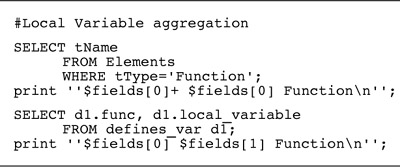
<function>+ <function> Function
this specifies that the element <function> should be aggregated into <function>+, which will have the type Function.
The second code portion hides the local variables from the visualization. The SQL query identifies the local variables for each function defined by selecting each tuple in the defines_var table. Thus in the perl expression, $fields[0] corresponds to the func field and $fields[1] corresponds to the local_ variable field. So the output is of the form:
<function>+ <variable> Function
That is, each local variable for a function is to be added to that function's <function>+ aggregate. The order of execution of these two code segments is not important, as the final results of applying both of these queries is sorted.
The result of applying the code segments is represented graphically in Figure 10.10.

The primary mechanism for manipulating the extracted information is inverse mappings. Examples include the following:
• Identify types
• Aggregate local variables into functions
• Aggregate members into classes
• Compose architecture-level elements
An example of a query that identifies an architectural element is shown in Figure 10.11. This query identifies the Logical_Interaction architectural element, and says that if the class name is Presentation, Bspline, or Color, or if the class is a subclass of Presentation, it belongs in the Logical_Interaction element.
Code segments are written in this way for abstracting from the lower-level information to generate architecture-level views. The reconstructor builds these segments to test hypotheses about the system. If a particular segment does not yield useful results, it can be discarded. The reconstructor iterates through this process until useful architectural views have been obtained.

The following are some practical considerations in applying this step of the method.
• Be prepared to work with the architect closely and to iterate several times on the architectural abstractions that you create. This is particularly so in cases where the system has no explicit, documented architecture. (See the sidebar Playing “Spot the Architecture.”) In such cases, you can create architectural abstractions as hypotheses and test these hypotheses by creating the views and showing them to the architect and other stakeholders. Based on the false negatives and false positives found, the reconstructor may decide to create new abstractions, resulting in new Dali code segments to apply (or perhaps even new extractions that need to be done).
Figure 10.12. Example of a bad code segment that relies on the explicit listing of elements of interest
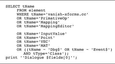
• When developing code segments, try to build ones that are succinct and that do not list every source element. The code segment shown in Figure 10.11 is an example of a good segment; an example of a bad one in this regard, is shown in Figure 10.12. In the latter, the source elements comprising the architectural element of interest are simply listed; this makes the segment difficult to use, understand, and re-use.
• Code segments can be based on naming conventions, if the naming conventions are used consistently throughout the system. An example is one where all functions, data, and files that belong to the Interface element begin with i_.
• Code segments can be based on the directory structure where files and functions are located. Element aggregations can be based on these directories.
• Architecture reconstruction is the effort of redetermining architectural decisions, given only the result of these decisions in the actual artifacts (i.e., the code that implements them). As reconstruction proceeds, information must be added to re-introduce the architectural decisions which introduces bias from the reconstructor and thus reinforces the need for a person knowledgeable in the architecture to be involved.
To illustrate the process of reconstruction, we will walk through a typical set of code segments created in Dali to reconstruct the architecture for UCMEdit, a system for creating and editing Buhr-style use case maps. We will show how the reconstructor moved from the raw data of a set of extracted views to a simple, elegant picture of the software architecture.
Table 10.2 shows the elements and relations initially extracted from the UCMEdit source code. Variable accesses are not included; that is, there are no function_reads_variable or function_assigns_variable relations. However, since these relations might be important for determining architectural coupling, a second extraction is engineered to capture them. Additionally, file depends_on file relations are extracted by processing the output from running the GNU make utility on the application's makefile.

Once the views of interest are extracted, functions thought to be “uninteresting” are filtered out, among them built-in functions, such as return, and standard C library functions, such as scanf and printf.
Next, an SQL database is populated with the extracted relations. As mentioned in Section 10.3, two additional database tables are constructed to catalog the elements and relationships—one identifies all defined elements; the other lists all identified relation types. The elements table has a field (called type) that stores the element's type (file, function, etc.).
Figure 10.13 shows the raw extracted model of those elements and relations, containing 830 nodes and 2,507 relations. At this point, the first order of business is to begin applying code segments to search for order within the chaos.

A reliable first step is to aggregate a function and all of the local variables that it defines into a new composite element. After the code segment shown in Figure 10.9 is applied, the models for UCMEdit still appear as an inscrutable web of nodes and arcs, but it is simpler than the extracted views of Figure 10.13 prior to the application of the function aggregation code segments. The UCMEdit model now shows 710 nodes and 2,321 relations.
We know that UCMEdit is an object-oriented system, and the next low-level code segment applied takes advantage of that knowledge. Similar in nature to that for collapsing functions, this code segment collapses together classes and their member variables and functions, representing them as a single class node. The resulting model was shown in Figure 10.5; it contains 233 nodes and 518 arcs—a significant visual simplification, although still not tractable.
But there are still many elements remaining that are unrelated to any extracted class. Hence, we have exposed either a deficiency in the extractors applied or ways in which these systems deviate from pure object-oriented design. In fact, both of these cases obtain.
Closer examination reveals that false positives are generated by the extraction code segments in the form of apparent calls to global functions that are actually calls to member functions. Moreover, several functions are indeed global, belonging to no class defined in the system. Of course, some global functions, in the form of system calls or windowing system primitives, are necessary. How these “leftover” cases are separated from the rest of the architecture is discussed next.
The model for UCMEdit is now a collection of files, classes, leftover functions, and global variables. Local variables have been aggregated into the functions in which they are defined, and member functions and member variables have been aggregated into their associated classes. At this point we can compose global variables and functions into the files in which they are defined, in much the same manner as functions and classes were composed. The resulting models, shown in Figure 10.14, contain three separate groups of elements: files, classes, and the remaining leftover functions. Again, a significant visual improvement but still not tractable.
Figure 10.14. The UCMEdit model showing (from top to bottom) classes, files, and “leftover” functions (arcs are hidden)

Until now, each code segment applied has been application independent but specific to the extraction techniques and to the domain of C++ software. The next code segment sets to be applied use expert knowledge of the UCMEdit architecture. Here the reconstruction process diverges from a rote analysis, where we apply off-the-shelf code segments, into opportunistic pattern recognition and definition, leveraging the kinds of information that a designer or experienced system programmer should know about a specific system's architecture.
The first application-specific knowledge that we apply to our sample system is as follows:
• It is an interactive, graphical application.
• It attempts to encapsulate access to the underlying windowing and graphics subsystem within a layer.
• The functions comprising the graphics libraries used (Xlib, XForms, and Mesa) have characteristic naming conventions.
These observations lead us to expect architectural patterns—the existence of subsystems, perhaps, or certain patterns of interaction. These expectations are in effect hypotheses, and to test them we check for the existence of the patterns. If the result simplifies the picture and matches our expectations, then our hypothesis is confirmed. We have likely discovered what the architect had in mind. Even if not, we have discovered a reasonable and useful handle with which to understand the system.
In the code segments shown in Figure 10.15, which are intended to identify the graphics subsystem, those external functions provide rendering and interaction functionality to the application. Consider the first code segment: It constructs a new table from the elements table by filtering out all functions that are members of classes (those that appear as the tDefines field in a tuple of the defines_fn relation). Then it selects from this new table all functions called by functions defined by subclasses of the Presentation class. Note that this code segment references subclasses of Presentation. In doing so, it implicitly identifies the layer that the original designers created to encapsulate accesses to the graphics subsystem. This information will be leveraged further. The second, third, and fourth code segments in this sequence identify functions defined by the Mesa, XForms, and Xlib libraries, respectively, by specifying code segments over the function names.
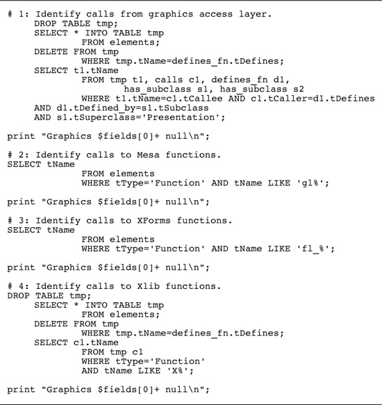
Code segments 2, 3, and 4 collectively identify an architectural element, Graphics, which does not exist in the extracted information but does exist in the as-designed architecture. This is an example of relating the as-implemented and as-designed architectures through a cumulative series of code segment applications. The results, in UCMEdit model, are shown in Figure 10.16.
Figure 10.16. UCMEdit model showing the graphics subsystem, classes, files, and remaining functions (arcs are hidden)

Note that the names of the elements to be aggregated into the Graphics element include the '+' that was appended by the code segments in the figure. This technique thus refers to previously constructed composite elements without the code segments explicitly querying the database for them.
Examining Figure 10.16, we see that there are only two leftover functions remaining: fabs and []; the latter is obviously an extraction error while the former is a math library function that should have been filtered out along with standard C library and built-in functions. Regardless, neither is of interest and so they can be pruned from the model.
Of course, the determination of which functions are “interesting” or “uninteresting” depends on the goals of the reconstruction. A reconstructor interested in a different aspect of the system, such as how its subsystems depend on platform-specific or operating-system-specific libraries, would not have pruned these functions from the concrete model, but would more likely have aggregated them into a layer to analyze how they are used by the rest of the application. We are interested in constructing an architectural representation of the application-specific part of the system, so we remove these functions.
A second common application-based code segment takes advantage of knowledge about the relationship between classes and files in the example applications. First, a source (.cc) file will contain functions for at most one class; second, a header (.h) file will contain a definition for at most one class. This makes it possible to define a unique containment relationship: A class can include the header file in which it is defined and the source file that contains its functions. The code segment that generates these aggregations is shown in Figure 10.17.

We see one additional feature of these specifications in this example: The last field in the perl expression associated with the first code segment ($fields[0]++) specifies a renaming of the element being aggregated. In this code segment, we are aggregating classes (named with trailing '+'s because of the class-collapsing code segments of Section 10.4) into new composite elements. The names of the new composites are <class>+; the original class composites are renamed <class>++. The results are shown in Figure 10.18.

UCMEdit was constructed as a prototype intended to demonstrate the advantages of computer-based editing of use case maps. Since over-arching architectural design of the application was not considered at the start of development, identification of architectural elements from the concrete model must be guided by an understanding of the application's structure as it stands at the completion of development. Our understanding of the application will be imposed on the model via direct manipulation, as follows.
First, we know (and can tell by observation of the model) that callbacks.cc is central to the structure of the application, containing all of the system's event handlers and the bulk of the user interface implementation. Second, we can observe the obvious relationships between the two remaining files and the classes to which they are connected—interpolate.cc is associated exclusively with BSpline, and fisheye.cc is used only by Box and Component. Third, we may now reapply our knowledge of the structure of the system's graphics encapsulation, or presentation, layer; it is embodied in the Presentation class and its subclasses. Fourth, we can make the observation that the List, ListItem, and ListIterator classes are functionally related to one another and are used by almost all of the other classes.
We realize the above observations by
• identifying the callbacks.cc file with an architectural element, Interaction.
• aggregating interpolate.cc into the BSpline element.
• aggregating the Presentation class and its subclasses into a Presentation element.
• aggregating the List, ListItem, and ListIterator classes into a List element and hiding it, treating it as a “utility layer.”
The results of these changes to the model are shown in Figure 10.19.

At this point, we need to carefully consider how we may further simplify this model. Automatic clustering based on graph-theoretic properties, such as interconnection strength, does not provide any insight. Another option is to attempt to build layers based on the organization generated by the graph layout algorithm, as shown in Figure 10.19, but this approach results in little functional consistency within the layers. In other words, these two hypotheses did not seem to be confirmed by the system, and so we did not pursue them. Considering the domain of use case maps, however, will suggest another hypothesis.
After looking at concepts from use case maps, we identified two broad categories of elements: those related to components and those related to paths, these being the two primary constructs comprising a use case map. DynamicArrow, Path, Point, Responsibility, Segment, Stub, and BSpline are related to paths; Box, Component, Dependent, Handle, and fisheye.cc are related to components. Figure 10.20 shows the effect of clustering these elements into two architectural elements: Path and Component.

In probing the connections among elements, we find that there are still a large number of interrelationships. While this is not necessarily harmful in itself, it suggests that UCMEdit's architecture lacks functional consistency within the elements and their connections.
Unfortunately, there are no significant improvements we can make to the UCMEdit model. The system was not well designed in that the mapping from functionality to software structure is complex. This makes the abstraction of functionally coherent high-level elements within UCMEdit's architecture impossible. However, we can take advantage of what we have learned to suggest improvements and to document what we know. The latter is especially important since we have discovered that UCMEdit lacks the conceptual integrity that often brings about intuitive understanding.
Because architectures are intangible, they often become lost or eroded over a system's lifetime. That is why we need techniques to recover or extract an architecture from a legacy system. This chapter provided an overview of a standard architecture reconstruction and showed an extended example of its application.
The mapping between architectures and source-code-level system artifacts is complex, and this makes architecture reconstruction a complex process that works best when it engages available human knowledge about the system under consideration. Tools are invaluable, especially when arrayed in a lightweight workbench ensemble, but human knowledge and insight are even more invaluable to guide the reconstruction process.
There are several reconstruction workbenches in existence. The Software Engineering Institute (SEI) has developed Dali [Kazman 99a]. Other examples include Sneed's reengineering workbench [Sneed 98], the software renovation factories of Verhoef and associates [Brand 97], and the rearchitecting tool suite by Philips Research [Krikhaar 99].
The Rigi Standard Form is discussed in [Müller 93]. The Rigi tool is described in [Wong 94].
[Bowman 99] outlines a method similar to Dali for extracting architectural documentation from the code of an implemented system. In one example, they reconstructed the architecture of the Linux system, analyzing source code using a cfx program (c-code fact extractor) to obtain symbol information from the code and generating a set of relations between the symbols. Then they manually created a tree-structured decomposition of the Linux system into subsystems and assigned the source files to them. Next, they used the grok fact manipulator tool to determine relations between the identified subsystems, and the lsedit visualization tool to visualize the extracted system structure. Refinement of the resultant structure was carried out by moving source files between subsystems.
Harris and associates outline a framework for architecture reconstruction using a combined bottom-up and top-down approach [Harris 95]. The framework consists of three parts: the architecture representation, the source code recognition engine and supporting library of recognition queries, and a “bird's-eye” program overview capability. The bottom-up analysis uses the bird's-eye view to display the system's file structure and source elements and to reorganize information into more meaningful clusters. The top-down analysis uses particular architectural patterns to define elements that should be found in the software. Recognition queries are then run to determine if the expected elements exist.
[Guo 99] outlines the semi-automatic architecture recovery method called ARM, for systems that are designed and developed using patterns. It consists of four main steps: (1) develop a concrete pattern recognition plan, (2) extract a source model, (3) detect and evaluate pattern instances, and (4) reconstruct and analyze the architecture. Case studies have been presented showing the use of the ARM method to reconstruct systems and check their conformance against their documented architectures.
1. Suppose you believed that the architecture for a system was layered. What information would you want to extract from the source code to confirm or refute this hypothesis?
2. Suppose you believed that the architecture for a system followed a shared repository style. What information would you want to extract from the source code to confirm or refute this hypothesis?
3. For each use of reconstruction mentioned in Section 10.1, specify the architectural views you would want to reconstruct.
4. Chapter 6 described a code template used to provide a consistent approach to high availability across the ISSS air traffic control system. Suppose you wanted to confirm that developers and maintainers had remained faithful to this template over the lifetime of the system. Describe the reconstruction process you would undertake.