
with Felix Bachmann, David Garlan, James Ivers, Reed Little, Robert Nord, and Judith Stafford
Note: Felix, James, Reed, and Robert are members of the SEI technical staff; David is an associate professor at Carnegie Mellon University's School of Computer Science; and Judith is an assistant professor at Tufts University's Department of Computer Science.
Books are the bees which carry the quickening pollen from one to another mind.
—James Russell Lowell
As we have seen over and over, the software architecture for a system plays a central role in system development and in the organization that produces it. The architecture serves as the blueprint for both the system and the project developing it. It defines the work assignments that must be carried out by design and implementation teams and it is the primary carrier of system qualities such as performance, modifiability, and security—none of which can be achieved without a unifying architectural vision. Architecture is an artifact for early analysis to make sure that the design approach will yield an acceptable system. Moreover, architecture holds the key to post-deployment system understanding, maintenance, and mining efforts. In short, architecture is the conceptual glue that holds every phase of the project together for all of its many stakeholders.
Documenting the architecture is the crowning step to crafting it. Even a perfect architecture is useless if no one understands it or (perhaps worse) if key stakeholders misunderstand it. If you go to the trouble of creating a strong architecture, you must describe it in sufficent detail, without ambiguity, and organized in such a way that others can quickly find needed information. Otherwise, your effort will have been wasted because the architecture will be unusable.
This chapter will help you decide what information about an architecture is important to capture, and it will discuss guidelines for capturing it. It will also discuss notations that are available, including UML.
The architecture for a system depends on the requirements levied on it, so too does the documentation for an architecture depend on the requirements levied on it—that is, how we expect it will be used. Documentation is decidedly not a case of “one size fits all.” It should be sufficiently abstract to be quickly understood by new employees but sufficiently detailed to serve as a blueprint for analysis. The architectural documentation for, say, security analysis may well be different from the architectural documentation we would hand to an implementor. And both of these will be different from what we put in a new hire's familiarization reading list.
Architecture documentation is both prescriptive and descriptive. That is, for some audiences it prescribes what should be true by placing constraints on decisions to be made. For other audiences it describes what is true by recounting decisions already made about a system's design.
All of this tells us that different stakeholders for the documentation have different needs—different kinds of information, different levels of information, and different treatments of information. We should not expect to produce one architectural document and have every consumer read it in the same way. Rather, we should produce documentation that helps a stakeholder quickly find the information that stakeholder is interested in, with a minimum of information that is irrelevant (to that stakeholder) standing in the way.
This might mean producing different documents for different stakeholders. More likely, it means producing a single documentation suite with a roadmap that will help different stakeholders navigate through it.
One of the most fundamental rules for technical documentation in general, and software architecture documentation in particular, is to write from the point of view of the reader. Documentation that was easy to write but is not easy to read will not be used, and “easy to read” is in the eye of the beholder—or in this case, the stakeholder.
Understanding who the stakeholders are and how they will want to use the documentation will help us organize it and make it accessible to and usable for them. Back in Chapter 2, we said that a primary purpose of architecture was to serve as a communication vehicle among stakeholders. Documentation facilitates that communication. Some examples of architectural stakeholders and the information they might expect to find in the documentation are given in Table 9.1.
In addition, each stakeholders come in two varieties: seasoned and new. A new stakeholder will want information similar in content to what his seasoned counterpart wants, but in smaller and more introductory doses. Architecture documentation is a key means for educating people who need an overview: new developers, funding sponsors, visitors to the project, and so forth.
Perhaps one of the most avid consumers of architectural documentation is none other than the architect at some time in the project's future—either the same person or a replacement but in either case someone guaranteed to have an enor mous stake in it. New architects are interested in learning how their predecessors tackled the difficult issues of the system and why particular decisions were made.
Even if the future architect is the same person, that architect will use the documentation as a repository of thought, as a storehouse of detailed design decisions too numerous and intertwined to be reproducible from memory alone.

Perhaps the most important concept associated with software architecture documentation is the view. Recall from Chapter 2 that we defined a software architecture for a system as “the structure or structures of the system, which comprise elements, the externally visible properties of those elements, and the relationships among them.” And we said that a view is a representation of a coherent set of architectural elements, as written by and read by system stakeholders. A structure is the set of elements itself, as they exist in software or hardware.
Also in Chapter 2 we discussed a software architecture as a complex entity that cannot be described in a simple one-dimensional fashion. The analogy with building architecture, if not taken too far, proves illuminating. There is no single rendition of a building architecture but many: the room layouts, the elevation drawings, the electrical diagrams, the plumbing diagrams, the ventilation diagrams, the traffic patterns, the sunlight and passive solar views, the security system plans, and many others. Which of these views is the architecture? None of them. Which views convey the architecture? All of them.
The concept of a view, which you can think of as capturing a structure, provides us with the basic principle of documenting software architecture:
Documenting an architecture is a matter of documenting the relevant views and then adding documentation that applies to more than one view.
This principle is useful because it breaks the problem of architecture documentation into more tractable parts, which provide the structure for the remainder of this chapter:
• Choosing the relevant views
• Documenting a view
• Documenting information that applies to more than one view
Recall that we introduced a set of structures and views in Chapter 2. What are the relevant views? This is where knowing your stakeholders and the uses they plan to make of the documentation will help you construct the documentation package they need. The many purposes that architecture can serve—as a mission statement for implementors, as the starting point for system understanding and asset recovery, as the blueprint for project planning, and so forth—are each represented by a stakeholder wanting and expecting to use the documentation to serve that purpose. Similarly, the quality attributes of most concern to you and the other stakeholders in the system's development will affect the choice of what views to document. For instance, a layered view will tell you about your system's portability. A deployment view will let you reason about your system's performance and reliability. And so it goes. These quality attributes are “spoken for” in the documentation by analysts (perhaps even the architect) who need to examine the architecture to make sure the quality attributes are provided.
In short, different views support different goals and uses. This is fundamentally why we do not advocate a particular view or a collection of views. The views you should document depend on the uses you expect to make of the documentation. Different views will highlight different system elements and/or relationships.
Table 9.2 shows a representative population of stakeholders and the kind of views they tend to find useful. You should use it to help you think about who your stakeholders are and what views might serve them well. Which views are available from which to choose? Chapter 2 listed a set of views, some of which are reflected in Table 9.2. Chapter 2 divided views into these three groups: module, component-and-connector (C&C), and allocation. This three-way categorization reflects the fact that architects need to think about their software in at least three ways at once:
- How it is structured as a set of implementation units
- How it is structured as a set of elements that have runtime behavior and interactions
- How it relates to non-software structures in its environment

Other views are available. A view simply represents a set of system elements and relationships among them, so whatever elements and relationships you deem useful to a segment of the stakeholder community constitute a valid view. Here is a simple three-step procedure for choosing the views for your project.
- Produce a candidate view list. Begin by building a stakeholder/view table, like Table 9.2, for your project. Your stakeholder list is likely to be different from the one in the table, but be as comprehensive as you can. For the columns, enumerate the views that apply to your system. Some views (such as decomposition or uses) apply to every system, while others (the layered view, most component-and-connector views such as client-server or shared data) only apply to systems designed that way. Once you have the rows and columns defined, fill in each cell to describe how much information the stakeholder requires from the view: none, overview only, moderate detail, or high detail.
- Combine views. The candidate view list from step 1 is likely to yield an impractically large number of views. To reduce the list to a manageable size, first look for views in the table that require only overview depth or that serve very few stakeholders. See if the stakeholders could be equally well served by another view having a stronger constituency. Next, look for views that are good candidates to be combined—that is, a view that gives information from two or more views at once. For small and medium projects, the implementation view is often easily overlaid with the module decomposition view. The module decomposition view also pairs well with uses or layered views. Finally, the deployment view usually combines well with whatever component-and-connector view shows the components that are allocated to hardware elements—the process view, for example.
- Prioritize. After step 2 you should have an appropriate set of views to serve your stakeholder community. At this point you need to decide what to do first. How you decide depends on the details specific to your project, but remember that you don't have to complete one view before starting another. People can make progress with overview-level information, so a breadth-first approach is often the best. Also, some stakeholders' interests supersede others. A project manager or the management of a company with which yours is partnering demands attention and information early and often.
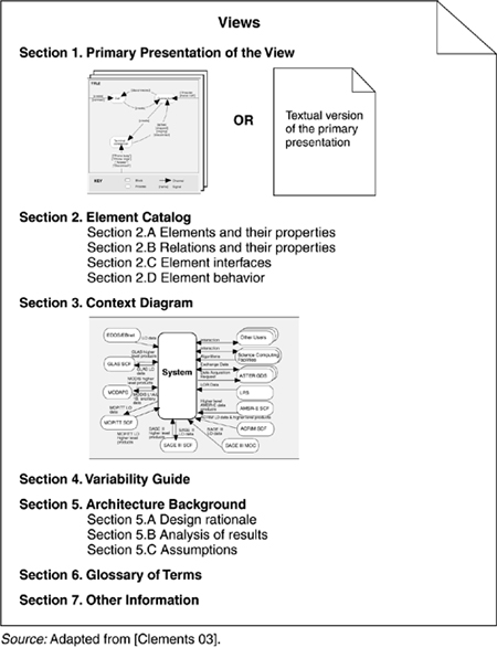
There is no industry-standard template for documenting a view, but the seven-part standard organization that we suggest in this section has worked well in practice. First of all, whatever sections you choose to include, make sure to have a standard organization. Allocating specific information to specific sections will help the documentation writer attack the task and recognize completion, and it will help the documentation reader quickly find information of interest at the moment and skip everything else.
- Primary presentation shows the elements and the relationships among them that populate the view. The primary presentation should contain the information you wish to convey about the system (in the vocabulary of that view) first. It should certainly include the primary elements and relations of the view, but under some circumstances it might not include all of them. For example, you may wish to show the elements and relations that come into play during normal operation, but relegate error handling or exceptional processing to the supporting documentation.
The primary presentation is usually graphical. In fact, most graphical notations make their contributions in the form of the primary presentation and little else. If the primary presentation is graphical, it must be accompanied by a key that explains, or that points to an explanation of, the notation or symbology used.
Sometimes the primary presentation can be tabular; tables are often a superb way to convey a large amount of information compactly. An example of a textual primary presentation is the A-7E module decomposition view illustrated in Chapter 3. A textual presentation still carries the obligation to present a terse summary of the most important information in the view. In Section 9.6 we will discuss using UML for the primary presentation.
- Element catalog details at least those elements and relations depicted in the primary presentation, and perhaps others. Producing the primary presentation is often what architects concentrate on, but without backup information that explains the picture, it is of little value.[1] For instance, if a diagram shows elements A, B, and C, there had better be documentation that explains in sufficient detail what A, B, and C are, and their purposes or the roles they play, rendered in the vocabulary of the view. For example, a module decomposition view has elements that are modules, relations that are a form of “is part of,” and properties that define the responsibilities of each module. A process view has elements that are processes, relations that define synchronization or other process-related interaction, and properties that include timing parameters.
In addition, if there are elements or relations relevant to the view that were omitted from the primary presentation, the catalog is where those are introduced and explained.
The behavior and interfaces of elements are two other aspects of an element catalog; these will be discussed shortly.
- Context diagram shows how the system depicted in the view relates to its environment in the vocabulary of the view. For example, in a component-and-connector view you show which component and connectors interact with external components and connectors, via which interfaces and protocols.
- Variability guide shows how to exercise any variation points that are a part of the architecture shown in this view. In some architectures, decisions are left unbound until a later stage of the development process, and yet the architecture must still be documented. An example of variability is found in software product lines where the product line architecture is suitable for multiple particular systems (discussed in Chapter 14). A variability guide should include documentation about each point of variation in the architecture, including
– the options among which a choice is to be made. In a module view, the options are the various versions or parameterizations of modules. In a component-and-connector view, they might include constraints on replication, scheduling, or choice of protocol. In an allocation view, they might include the conditions under which a software element would be allocated to a particular processor.
– the binding time of the option. Some choices are made at design time, some at build time, and others at runtime.
- Architecture background explains why the design reflected in the view came to be. The goal of this section is to explain to someone why the design is as it is and to provide a convincing argument that it is sound. An architecture background includes
– rationale, explaining why the decisions reflected in the view were made and why alternatives were rejected.
– analysis results, which justify the design or explain what would have to change in the face of a modification.
– assumptions reflected in the design.
- Glossary of terms used in the views, with a brief description of each.
- Other information. The precise contents of this section will vary according to the standard practices of your organization. They might include management information such as authorship, configuration control data, and change histories. Or the architect might record references to specific sections of a requirements document to establish traceability. Strictly speaking, information such as this is not architectural. Nevertheless, it is convenient to record it alongside the architecture, and this section is provided for that purpose. In any case, the first part of this section must detail its specific contents.
Figure 9.1 summarizes the parts of the documentation just described.
Views present structural information about the system. However, structural information is not sufficient to allow reasoning about some system properties. Reasoning about deadlock, for example, depends on understanding the sequence of interactions among the elements, and structural information alone does not present this sequencing information. Behavior descriptions add information that reveals the ordering of interactions among the elements, opportunities for concurrency, and time dependencies of interactions (at a specific time or after a period of time).
Behavior can be documented either about an element or about an ensemble of elements working in concert. Exactly what to model will depend on the type of system being designed. For example, if it is a real-time embedded system, you will need to say a lot about timing properties and the time of events. In a banking system, the sequence of events (e.g., atomic transactions and rollback procedures) is more important than the actual time of events being considered. Different modeling techniques and notations are used depending on the type of analysis to be performed. In UML, sequence diagrams and statecharts are examples of behavioral descriptions. These notations are widely used.
Statecharts are a formalism developed in the 1980s for describing reactive systems. They add a number of useful extensions to traditional state diagrams such as nesting of state and “and” states, which provide the expressive power to model abstraction and concurrency. Statecharts allow reasoning about the totality of the system. All of the states are assumed to be represented and the analysis techniques are general with respect to the system. That is, it is possible to answer a question such as Will the response time to this stimulus always be less than 0.5 seconds?
A sequence diagram documents a sequence of stimuli exchanges. It presents a collaboration in terms of component instances and their interactions and shows the interaction arranged in time sequence. The vertical dimension represents time and the horizontal dimension represents different components. Sequence diagrams allow reasoning based on a particular usage scenario. They show how the system reacts to a particular stimulus and represent a choice of paths through the system. They make it possible to answer a question such as What parallel activities occur when the system is responding to these specific stimuli under these specific conditions?
An interface is a boundary across which two independent entities meet and interact or communicate with each other. Our definition of software architecture in Chapter 2 made it clear that elements' interfaces—carriers of the properties externally visible to other elements—are architectural. Since you cannot perform analyses or system building without them, documenting interfaces is an important part of documenting architecture.
Documenting an interface consists of naming and identifying it and documenting its syntactic and semantic information. The first two parts constitute an interface's “signature.” When an interface's resources are invokable programs, the signature names the programs and defines their parameters. Parameters are defined by their order, data type, and (sometimes) whether or not their value is changed by the program. A signature is the information that you would find about the program, for instance, in an element's C or C++ header file or in a Java interface.
Signatures are useful (for example, they can enable automatic build checking), but are only part of the story. Signature matching will guarantee that a system will compile and/or link successfully. However, it guarantees nothing about whether the system will operate successfully, which is after all the ultimate goal. That information is bound up in the semantics to the interface, or what happens when resources are brought into play.
An interface is documented with an interface specification, which is a statement of element properties the architect chooses to make known. The architect should expose only what is needed to interact with the interface. Put another way, the architect chooses what information is permissible and appropriate for people to assume about the element, and what is unlikely to change. Documenting an interface is a matter of striking a balance between disclosing too little information and disclosing too much. Too little information will prevent developers from successfully interacting with the element. Too much will make future changes to the system more difficult and widespread and make the interface too complicated for people to understand. A rule of thumb is to focus on how elements interact with their operational environments, not on how they are implemented. Restrict the documentation to phenomena that are externally visible.
Elements that occur as modules often correspond directly to one or more elements in a component-and-connector view. The module and component-and-connector elements are likely to have similar, if not identical, interfaces and documenting them in both places would produce needless duplication. To avoid that, the interface specification in the component-and-connector view can point to the interface specification in the module view, and only contain the information specific to its view. Similarly, a module may appear in more than one module view—such as the module decomposition or uses view. Again, choose one view to hold the interface specification and refer to it in the others.
Here is a suggested standard organization for interface documentation. You may wish to modify it to remove items not relevant to your situation, or add items unique to it. More important than which standard organization you use is the practice of using one. Use what you need to present an accurate picture of the element's externally visible interactions for the interfaces in your project.
- Interface identity. When an element has multiple interfaces, identify the individual interfaces to distinguish them. This usually means naming them. You may also need to provide a version number.
- Resources provided. The heart of an interface document is the resources that the element provides. Define them by giving their syntax, their semantics (what happens when they are used), and any restrictions on their usage. Several notations exist for documenting an interface's syntax. One is the OMG's Interface Definition Language (IDL), used in the CORBA community. It provides language constructs to describe data types, operations, attributes, and exceptions. The only language support for semantic information is a comment mechanism. Most programming languages have built-in ways to specify the signature of an element. C header (
.h) files and Ada package specifications are two examples. Finally, using the<<interface>>stereotype in UML (as shown in Figure 9.4) provides the means for conveying syntactic information about an interface. At a minimum, the interface is named; the architect can also specify signature information.• Resource syntax. This is the resource's signature. The signature includes any information another program will need to write a syntactically correct program that uses the resource. The signature includes the resource name, names and logical data types of arguments (if any), and so forth.
• Resource semantics. This describes the result of invoking the resource. It might include
– assignment of values to data that the actor invoking the resource can access. It might be as simple as setting the value of a return argument or as far-reaching as updating a central database.
– events that will be signaled or messages that will be sent as a result of using the resource.
– how other resources will behave in the future as the result of using this resource. For example, if you ask a resource to destroy an object, trying to access that object in the future through other resources will produce quite a different outcome (an error).
– humanly observable results. These are prevalent in embedded systems; for example, calling a program that turns on a display in a cockpit has a very observable effect: The display comes on.
In addition, the statement of semantics should make it clear whether the resource execution will be atomic or may be suspended or interrupted. The most widespread notation for conveying semantic information is natural language. Boolean algebra is often used to write down preconditions and postconditions, which provide a relatively simple and effective method for expressing semantics. Traces are also used to convey semantic information by writing down sequences of activities or interactions that describe the element's response to a specific use.
• Resource usage restrictions. Under what circumstances may this resource be used? Perhaps data must be initialized before it can be read, or a particular method cannot be invoked unless another is invoked first. Perhaps there is a limit on the number of actors that can interact via this resource at any instant. Perhaps only one actor can have ownership and be able to modify the element whereas others have only read access. Perhaps only certain resources or interfaces are accessible to certain actors to support a multi-level security scheme. If the resource requires that other resources be present, or makes other assumptions about its environment, these should be documented.
- Data type definitions. If any interface resources employ a data type other than one provided by the underlying programming language, the architect needs to communicate the definition of that data type. If it is defined by another element, then a reference to the definition in that element's documentation is sufficient. In any case, programmers writing elements using such a resource need to know (a) how to declare variables and constants of the data type; (b) how to write literal values in the data type; (c) what operations and comparisons may be performed on members of the data type; and (d) how to convert values of the data type into other data types, where appropriate.
- Exception definitions. These describe exceptions that can be raised by the resources on the interface. Since the same exception might be raised by more than one resource, it is often convenient to simply list each resource's exceptions but define them in a dictionary collected separately. This section is that dictionary. Common exception-handling behavior can also be defined here.
- Variability provided by the interface. Does the interface allow the element to be configured in some way? These configuration parameters and how they affect the semantics of the interface must be documented. Examples of variability include the capacities of visible data structures and the performance characteristics of underlying algorithms. Name and provide a range of values for each configuration parameter and specify the time when its actual value is bound.
- Quality attribute characteristics of the interface. The architect needs to document what quality attribute characteristics (such as performance or reliability) the interface makes known to the element's users. This information may be in the form of constraints on implementations of elements that will realize the interface. Which qualities you choose to concentrate on and make promises about will depend on context.
- Element requirements. What the element requires may be specific, named resources provided by other elements. The documentation obligation is the same as for resources provided: syntax, semantics, and any usage restrictions. Often it is convenient to document information like this as a set of assumptions that the element's designer has made about the system. In this form, they can be reviewed by experts who can confirm or repudiate the assumptions before design has progressed too far.
- Rationale and design issues. As with rationale for the architecture (or architectural views) at large, the architect should record the reasons for an element's interface design. The rationale should explain the motivation behind the design, constraints and compromises, what alternative designs were considered and rejected (and why), and any insight the architect has about how to change the interface in the future.
- Usage guide. Item 2 and item 7 document an element's semantic information on a per resource basis. This sometimes falls short of what is needed. In some cases semantics need to be reasoned about in terms of how a broad number of individual interactions interrelate. Essentially, a protocol is involved that is documented by considering a sequence of interactions. Protocols can represent the complete behavior of the interaction or patterns of usage that the element designer expects to come up repeatedly. If interacting with the element via its interface is complex, the interface documentation should include a static behavioral model such as a statechart, or examples of carrying out specific interactions in the form of sequence diagrams. This is similar to the view-level behaviors presented in the previous section, but focused on a single element.
Figure 9.2 summarizes this template which is an expansion of section 2.C from Figure 9.1.

[1] To emphasize that it is but a sketch of the complete picture, we call a primary presentation by itself an architectural cartoon.
We now turn to the complement of view documentation, which is capturing the information that applies to more than one view or to the documentation package as a whole. Cross-view documentation consists of just three major aspects, which we can summarize as how-what-why:
- How the documentation is laid out and organized so that a stakeholder of the architecture can find the information he or she needs efficiently and reliably. This part consists of a view catalog and a view template.
- What the architecture is. Here, the information that remains to be captured beyond the views themselves is a short system overview to ground any reader as to the purpose of the system; the way the views are related to each other; a list of elements and where they appear; and a glossary that applies to the entire architecture.
- Why the architecture is the way it is: the context for the system, external constraints that have been imposed to shape the architecture in certain ways, and the rationale for coarse-grained large-scale decisions.
Figure 9.3 summarizes these points.

Every suite of architectural documentation needs an introductory piece to explain its organization to a novice stakeholder and to help that stakeholder access the information he or she she is most interested in. There are two kinds of “how” information:
• A view catalog
• A view template
A view catalog is the reader's introduction to the views that the architect has chosen to include in the suite of documentation.
When using the documentation suite as a basis for communication, it is necessary for a new reader to determine where particular information can be found. A catalog contains this information. When using the documentation suite as a basis for analysis, it is necessary to know which views contain the information necessary for a particular analysis. In a performance analysis, for example, resource consumption is an important piece of information, A catalog enables the analyst to determine which views contain properties relevant to resource consumption.
There is one entry in the view catalog for each view given in the documentation suite. Each entry should give the following:
- The name of the view and what style it instantiates
- A description of the view's element types, relation types, and properties
- A description of what the view is for
- Management information about the view document, such as the latest version, the location of the view document, and the owner of the view document
The view catalog is intended to describe the documentation suite, not the system being documented. Specifics of the system belong in the individual views, not in the view catalog. For instance, the actual elements contained in a view are listed in the view's element catalog.
A view template is the standard organization for a view. Figure 9.1 and the material surrounding it provide a basis for a view template by defining the standard parts of a view document and the contents and rules for each. The purpose of a view template is that of any standard organization: It helps a reader navigate quickly to a section of interest, and it helps a writer organize the information and establish criteria for knowing how much work is left to do.
This section provides information about the system whose architecure is being documented, the relation of the views to each other, and an index of architectural elements.
This is a short prose description of what the system's function is, who its users are, and any important background or constraints. The intent is to provide readers with a consistent mental model of the system and its purpose. Sometimes the project at large will have a system overview, in which case this section of the architectural documentation simply points to that.
Since all of the views of an architecture describe the same system, it stands to reason that any two views will have much in common. Helping a reader of the documentation understand the relationships among views will give him a powerful insight into how the architecture works as a unified conceptual whole. Being clear about the relationship by providing mappings between views is the key to increased understanding and decreased confusion.
For instance, each module may map to multiple runtime elements, such as when classes map to objects. Complications arise when the mappings are not one to one, or when runtime elements of the system do not exist as code elements at all, such as when they are imported at runtime or incorporated at build or load time. These are relatively simple one- (or none-) to-many mappings. In general, though, parts of elements in one view can map to parts of elements in another view.
It is not necessary to provide mappings between every pair of views. Choose the ones that provide the most insight.
The element list is simply an index of all of the elements that appear in any of the views, along with a pointer to where each one is defined. This will help stakeholders look up items of interest quickly.
Similar in purpose to the rationale for a view or the rationale for an interface design, cross-view rationale explains how the overall architecture is in fact a solution to its requirements. One might use the rationale to explain
• the implications of system-wide design choices on meeting the requirements or satisfying constraints.
• the effect on the architecture when adding a foreseen new requirement or changing an existing one.
• the constraints on the developer in implementing a solution.
• decision alternatives that were rejected.
In general, the rationale explains why a decision was made and what the implications are in changing it.
We have concentrated on the kind of information that should be included in architecture documentation. Architecture in some sense expresses what is essential about a software system, and that essence is independent of languages and notations to capture it. Nevertheless, today the Unified Modeling Language (UML) has emerged as the de facto standard notation for documenting a software architecture. However, it must be said that UML makes its main contribution in a view's primary presentation, and its secondary contribution in the behavior of an element or group of elements. It is up to the architect to augment the UML pictures with the necessary supporting documentation (the element catalog, the rationale, and so forth) that a responsible job requires. UML provides no direct support for components, connectors, layers, interface semantics, or many other aspects of a system that are supremely architectural.
Still, in most cases we can use the constructs that UML does offer to achieve satisfactory effects, at least in crafting the primary presentations of architectural views. We begin by discussing module views.
Recall that a module is a code or implementation unit and a module view is an enumeration of modules together with their interfaces and their relations.
Figure 9.4 shows how module interfaces can be represented in UML. UML uses a “lollipop” to denote an interface, which can be appended to classes and subsystems, among other things.

UML also allows a class symbol (box) to be stereotyped as an interface; the open-headed dashed arrow shows that an element realizes an interface. The bottom of the class symbol can be annotated with the interface's signature information: method names, arguments, argument types, and so forth. The lollipop notation is normally used to show dependencies from elements to the interface, while the box notation allows a more detailed description of the interface's syntax, such as the operations it provides.
UML provides a variety of constructs to represent different kinds of modules. Figure 9.5 shows some examples. UML has a class construct, which is the object-oriented specialization of a module. Packages can be used in cases where grouping of functionality is important, such as to represent layers and classes. The subsystem construct can be used if a specification of interface and behavior is required.
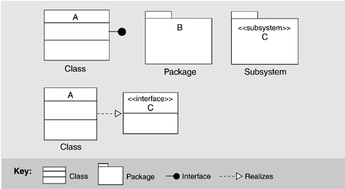
Figure 9.6 shows how the relations native to module views are denoted using UML. Module decomposition relies on the “is-part-of” relation. The module uses view relies on the dependency relation, and the module class view relies on the generalization, or “is-a” relation (also called “inheritance”).

In UML, the subsystem construct can be used to represent modules that contain other modules; the class box is normally used for the leaves of the decomposition. Subsystems are used both as packages and as classifiers. As packages, they can be decomposed and hence are suitable for module aggregation. As classifiers, they encapsulate their contents and can provide an explicit interface. Aggregation is depicted in one of three ways in UML:
• Modules may be nested (see Figure 9.7 left).
Figure 9.7. Decomposition in UML with nesting. The aggregate module is shown as a package (left); decomposition in UML with arcs (right).
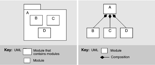
• A succession of two diagrams (possibly linked) can be shown, where the second is a depiction of the contents of a module shown in the first.
• An arc denoting composition is drawn between the parent and the children (see Figure 9.7 right).
In UML, composition is a form of aggregation with implied strong ownership—that is, parts live and die with the whole. If module A is composed of modules B and C, then B or C cannot exist without A, and if A is destroyed at runtime, so are B and C. Thus, UML's composition relation has implications beyond the structuring of the implementation units; the relation also endows the elements with a runtime property. As an architect, you should make sure you are comfortable with this property before using UML's composition relation.
Expressing generalization is at the heart of UML in which modules are shown as classes (although they may also be shown as subsystems). Figure 9.8 shows the basic notation available in UML.

The two diagrams in Figure 9.8 are semantically identical. UML allows an ellipsis (…) in place of a submodule, indicating that a module can have more children than shown and that additional ones are likely. Module Shape is the parent of modules Polygon, Circle, and Spline, each of which is a subclass, child, or descendant of Shape. Shape is more general, while its children are specialized versions.
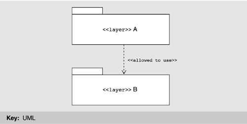
The basic notation for dependency was shown in Figure 9.6. The most architecturally significant manifestation of dependency is found in layers. Sadly, UML has no built-in primitive corresponding to a layer. However, it can represent simple layers using packages, as shown in Figure 9.9. These are general-purpose mechanisms for organizing elements into groups. UML has predefined packages for systems and subsystems. We can introduce an additional package for layers by defining it as a package stereotype. A layer can be shown as a UML package with the constraints that it groups modules together and that the dependency between packages is “allowed to use.” We can designate a layer using the package notation with the stereotype name <<layer>> preceding the layer name, or introduce a new visual form, such as a shaded rectangle.
There is no single preferred strategy to document component-and-connector (C&C) views in UML, but a number of alternatives. Each alternative has its advantages and disadvantages. One natural candidate for representing component-and-connector types begins with the UML class concept.
Figure 9.10 illustrates the general idea using a simple pipe-and-filter system. Here, the filter architectural type is represented as the UML class Filter. Instances of filters, such as Splitter, are represented as corresponding objects in an object instance diagram. To provide a namespace boundary, we enclose the descriptions in packages. The representation of MergeAndSort, denoted Details, would be shown as another package elsewhere.
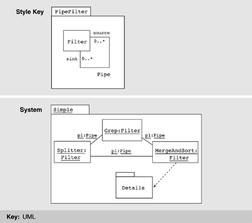
We now take a closer look at this strategy.
The type/instance relationship in architectural descriptions is a close match to the class/object relationship in a UML model. UML classes, like component types in architectural descriptions, are first-class entities and are rich structures for capturing software abstractions. The full set of UML descriptive mechanisms is available to describe the structure, properties, and behavior of a class, making this a good choice for depicting detail and using UML-based analysis tools. Properties of architectural components can be represented as class attributes or with associations; behavior can be described using UML behavioral models; and generalization can be used to relate a set of component types. The semantics of an instance or type can also be elaborated by attaching one of the standard stereotypes; for example, the «process» stereotype can be attached to a component to indicate that it runs as a separate process. Note that the relationship between MergeAndSort and its substructure is indicated using a dependency relation.
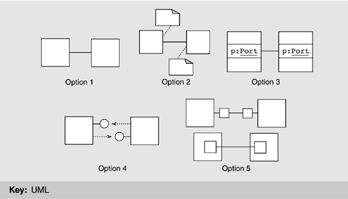
Interfaces to components, sometimes called ports, can be shown in five ways, as shown in Figure 9.11, described in increasing order of expressiveness. However, as expressiveness rises so does complexity, so you should pick the first strategy that will serve your purposes.
• Option 1: No explicit representation. Leaving out interfaces leads to the simplest diagrams but suffers from the obvious problem that there is no way to characterize the names or the properties of the interfaces in the primary presentation. Still, this choice might be reasonable if the components have only one interface, if the interfaces can be inferred from the system topology, or if the diagram is refined elsewhere.
• Option 2: Interfaces as annotations. Representing interfaces as annotations provides a home for information about them, although annotations have no semantic value in UML so cannot be used as a basis for analysis. Again, if the detailed properties of an interface are not of concern, this approach might be reasonable.
• Option 3: Interfaces as class/object attributes. Treating interfaces as attributes of a class/object makes them part of the formal structural model, but they can have only a simple representation in a class diagram—essentially, a name and a type. This restriction limits the expressiveness of this option.
• Option 4: Interfaces as UML interfaces. The UML lollipop notation provides a compact description of an interface in a class diagram depicting a component type. In an instance diagram, a UML association role, corresponding to an interface instance and qualified by the interface type name, provides a compact way to show that a component instance is interacting through a particular interface instance. This approach provides visually distinct depictions of components and interfaces, in which interfaces can clearly be seen as subservient.
However, this strategy provides no means to depict the services required from a component's environment, often a key part of an interface. Furthermore, it is meaningful for a component type to have several instances of the same interface type, but it is not meaningful to say that a class realizes several versions of one UML interface. For example, there is no easy way to define a Splitter filter type that has two output ports of the same “type” using this technique. Finally, unlike classes, UML interfaces do not have attributes or substructure.
• Option 5: Interfaces as classes. Describing interfaces as classes contained by a component type overcomes the lack of expressiveness of the previous alternatives: We can now represent interface substructure and indicate that a component type has several interfaces of the same type. A component instance is modeled as an object containing a set of interface objects. However, by representing interfaces as classes, we not only clutter the diagram but also lose clear visual discrimination between interfaces and components. We could use a notational variation in which the interfaces are contained classes, as shown in the lower part of option 5 in Figure 9.11. Indicating points of interaction is counterintuitive, however, as containment usually indicates that a class owns other classes whose instances may or may not be accessible through instances of the parent class.
There are three reasonable options for representing connectors. Again, the choice is between expressiveness and semantic match on the one hand and complexity on the other.
• Option 1: Connector types as associations and connector instances as links. In an architectural box-and-line diagram of a system, the lines between components are connectors. One tempting way to represent connectors in UML is as associations between classes or links between objects. This approach is visually simple, provides a clear distinction between components and connectors, and uses the most familiar relationship in UML class diagrams: association. Moreover, associations can be labeled, and a direction associated with the connector can be indicated with an arrow. Unfortunately, connectors and associations have different meanings. A system in an architectural description is built up by choosing components with behavior exposed through their interfaces and connecting them with connectors that coordinate their behaviors. A system's behavior is defined as the collective behavior of a set of components whose interaction is defined and limited by the connections between them.
In contrast, although an association, or link, in UML represents a potential for interaction between the elements it relates, the association mechanism is primarily a way of describing a conceptual relationship between two elements. In addition, an association is a relationship between UML elements, so it cannot stand on its own in a UML model. Consequently, a connector type cannot be represented in isolation. Instead, you must resort to naming conventions or to stereotypes whose meanings are captured by description in UML's object constraint language. Further, the approach does not allow you to specify a connector's interfaces.
• Option 2: Connector types as association classes. One solution to the lack of expressiveness is to qualify the association with a class that represents the connector type. In this way, the connector type or connector attributes can be captured as attributes of a class or object. Unfortunately, this technique still does not provide any way of explicitly representing connector interfaces.
• Option 3: Connector types as classes and connector instances as objects. One way to give connectors first-class status in UML is to represent connector types as classes and connector instances as objects. Using classes and objects, we have the same four options for representing roles as we had for interfaces: not at all, as annotations, as interfaces realized by a class, or as child classes contained by a connector class. Given a scheme for representing interfaces, an attachment between a component's interface and a connector's interface may be represented as an association or a dependency.
In addition to representing individual components and connectors and their types, we also need to encapsulate graphs of components and connectors: systems. Three options are available.
• Option 1: Systems as UML subsystems. The primary UML mechanism for grouping related elements is the package. In fact, UML defines a standard package stereotype, called «subsystem», to group UML models that represent a logical part of a system. The choice of subsystems is appropriate for any mapping of components and connectors, and it works particularly well for grouping classes. One of the problems with using subsystems, as defined in UML 1.4, is that, although they are both a classifier and a package, the meaning is not entirely clear. Some have argued that we should be able to treat a subsystem as an atomic class-like entity at certain stages in the development process and later be able to refine it in terms of a more detailed substructure. Having the ability to do this would make the subsystem construct more appropriate for modeling architectural components.
• Option 2: Systems as contained objects. Object containment can be used to represent systems. Components are represented as instances of contained classes, and connectors are modeled using one of the options outlined earlier. Objects provide a strong encapsulation boundary and carry with them the notion that each instance of the class has the associated “substructure.” However, this approach has problems, the most serious being that associations, used to model connectors, between contained classes are not scoped by the class. That is, it is not possible to say that a pair of classes interacts via a particular connector, modeled as an association, only in the context of a particular system. So, for example, indicating that two contained classes interact via an association is valid for instances of classes used anywhere else in the model.
• Option 3: Systems as collaborations. A set of communicating objects connected by links is described in UML using a collaboration. If we represent components as objects, we can use collaborations to represent systems. A collaboration defines a set of participants and relationships that are meaningful for a given purpose, which in this case is to describe the runtime structure of the system. The participants define classifier roles that objects play, or conform to, when interacting. Similarly, the relationships define association roles that links must conform to.
Collaboration diagrams can be used to present collaborations at either the specification or the instance level. A specification-level collaboration diagram shows the roles, defined within the collaboration, arranged in a pattern to describe the system substructure. An instance-level collaboration diagram shows the objects and links conforming to the roles at the specification level and interacting to achieve the purpose. Therefore, a collaboration presented at the instance level is best used to represent the runtime structure of the system.
Figure 9.12 illustrates this approach. The Filter architectural type is represented as previously. Instances of filters and pipes are represented as corresponding classifier roles—for example, /Splitter indicates the Splitter role—and association roles. The objects and links conforming to those roles are shown in the collaboration diagram at the instance level, indicated by underscored names.
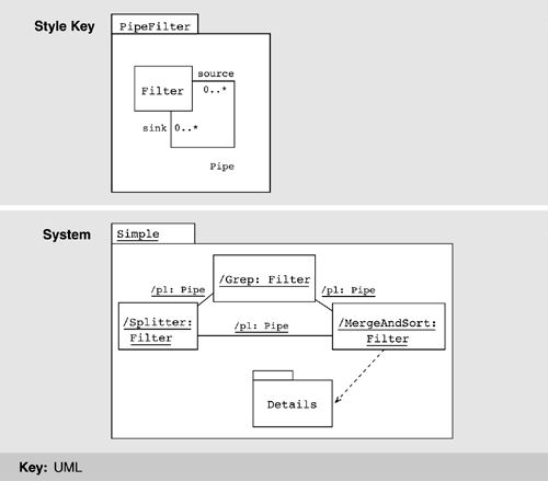
Although this is a natural way to describe runtime structures, it leaves no way to explicitly represent system-level properties. There is also a semantic mismatch; a collaboration describes a representative interaction between objects and provides a partial description, whereas an architectural configuration is meant to capture a complete description.
In UML, a deployment diagram is a graph of nodes connected by communication associations. Figure 9.13 provides an example. Nodes may contain component instances, which indicates that the component lives or runs on the node. Components may contain objects, which indicates that the object is part of the component. Components are connected to other components by dashed-arrow dependencies (possibly through interfaces). This indicates that one component uses the services of another; a stereotype may be used to indicate the precise dependency if needed. The deployment type diagram may also be used to show which components may run on which nodes, by using dashed arrows with the stereotype «supports».

A node is a runtime physical object that represents a processing resource, generally having at least a memory and often processing capability as well. Nodes include computing devices but also human or mechanical processing resources. Nodes may represent types of instances. Runtime computational instances, both objects and components, may reside on node instances.
Nodes may be connected by associations to other nodes. An association indicates a communication path between them. The association may have a stereotype to indicate the nature of the communication path (for example, the kind of channel or network).
The nesting of symbols within the node symbol signifies a composition association between a node class and constituent classes or a composition link between a node object and constituent objects.
An architecture is worthless if nobody can understand what it is or how to use it. Documenting an architecture is the crowning step in creating it, freeing the architect from having to answer hundreds of questions about it and serving to capture it for current and future stakeholders.
You must understand the stakeholders of the architecture and how they expect to use the documentation. Treat the task of documenting an architecture as documenting the set of relevant views and then supplementing that with cross-view information. Use the stakeholders to help choose the relevant views.
Box-and-line diagrams, whether rendered in an informal notation or in something like UML, tell only a small part of the story. Augment them with supporting documentation that explains the elements and relationships shown in the primary presentation. Interfaces and behavior are important parts of the architecture picture.
This chapter presented a prescriptive organization for documenting software architectures. You may ask why we have not strictly adhered to it in the architectural case studies in this book. A fundamental principle of technical documentation of any kind, and software architecture documentation in particular, is to write so that the material is of the most use to the anticipated readers. Here, the reader wants an overview of the system, its motivations, and how it meets its quality goals—the reader isn't going to analyze it or build to it. Thus, the descriptions that we provide are less formal and less detailed than what we would recommend for construction or analysis. In that spirit, we use primary presentations (cartoons) to convey general information; however, in lieu of a formal element catalog to fill in the detail, we give a narrative description.
Much of the material in this chapter was adapted from [Clements 03]. For a more comprehensive treatment of architectural documentation, the interested reader should look there. The reader is also referred to [IEEE 00] for a communitywide standard for architectural documentation that is both consistent with this chapter and gives slightly different terminology.
Finally, there are many good references for the UML. However, the first, and the standard [Rumbaugh 99], still serves as a useful and comprehensive introduction. The Object Management Group is currently generating a version of UML intended to better enable the representation of the software architecture of a system. You can follow the progress of this effort at http://www.omg.org/uml/.
1. What views from this chapter are pertinent to a system you are currently working on? What views have you documented? Why is there a difference?
2. You are a new hire to a project. Lay out a sequence of documentation you would like to have to acquaint you with your new position.
3. What documentation would you need to do performance analysis?