The FAA has faced this problem [of complexity] throughout its decade-old attempt to replace the nation's increasingly obsolete air traffic control system. The replacement, called Advanced Automation System, combines all the challenges of computing in the 1990s. A program that is more than a million lines in size is distributed across hundreds of computers and embedded into new and sophisticated hardware, all of which must respond around the clock to unpredictable real-time events. Even a small glitch potentially threatens public safety.
—W. Wayt Gibbs [Gibbs 94]
Air traffic control (ATC) is among the most demanding of all software applications. It is hard real time, meaning that timing deadlines must be met absolutely; it is safety critical, meaning that human lives may be lost if the system does not perform correctly; and it is highly distributed, requiring dozens of controllers to work cooperatively to guide aircraft through the airways system. In the United States, whose skies are filled with more commercial, private, and military aircraft than any other part of the world, ATC is an area of intense public scrutiny. Aside from the obvious safety issues, building and maintaining a safe, reliable airways system requires enormous expenditures of public money. ATC is a multibillion-dollar undertaking.
This chapter is a case study of one part of a once-planned, next-generation ATC system for the United States. We will see how its architecture—in particular, a set of carefully chosen views (as in Chapter 2) coupled with the right tactics (as in Chapter 5)—held the key to achieving its demanding and wide-ranging requirements. Although this system was never put into operation because of budgetary constraints, it was implemented and demonstrated that the system could meet its quality goals.
In the United States, air traffic is controlled by the Federal Aviation Administration (FAA), a government agency responsible for aviation safety in general. The FAA is the customer for the system we will describe. As a flight progresses from its departure airport to its arrival airport, it deals with several ATC entities that guide it safely through each portion of the airways (and ground facilities) it is using. Ground control coordinates the movement of aircraft on the ground at an airport. Towers control aircraft flying within an airport's terminal control area, a cylindrical section of airspace centered at an airport. Finally, en route centers divide the skies over the country into 22 large sections of responsibility.
Consider an airline flight from Key West, Florida, to Washington, D.C.'s Dulles Airport. The crew of the flight will communicate with Key West ground control to taxi from the gate to the end of the runway, Key West tower during takeoff and climb-out, and then Miami Center (the en route center whose airspace covers Key West) once it leaves the Key West terminal control area. From there the flight will be handed off to Jacksonville Center, Atlanta Center, and so forth, until it enters the airspace controlled by Washington Center. From Washington Center, it will be handed off to the Dulles tower, which will guide its approach and landing. When it leaves the runway, the flight will communicate with Dulles ground control for its taxi to the gate. This is an oversimplified view of ATC in the United States, but it suffices for our case study. Figure 6.1 shows the hand-off process, and Figure 6.2 shows the 22 en route centers.
Figure 6.1. Flying from point A to point B in the U.S. air traffic control system.

Courtesy of Ian Worpole/Scientific American, 1994.

The system we will study is called the Initial Sector Suite System (ISSS), which was intended to be an upgraded hardware and software system for the 22 en route centers in the United States. It was part of a much larger government procurement that would have, in stages, installed similar upgraded systems in the towers and ground control facilities, as well as the transoceanic ATC facilities.
The fact that ISSS was to be procured as only one of a set of strongly related systems had a profound effect on its architecture. In particular, there was great incentive to adopt common designs and elements where possible because the ISSS developer also intended to bid on the other systems. After all, these different systems (en route center, tower, ground control) share many elements: interfaces to radio systems, interfaces to flight plan databases, interfaces to each other, interpreting radar data, requirements for reliability and performance, and so on. Thus, the ISSS design was influenced broadly by the requirements for all of the upgraded systems, not just the ISSS-specific ones. The complete set of upgraded systems was to be called the Advanced Automation System (AAS).
Ultimately, the AAS program was canceled in favor of a less ambitious, less costly, more staged upgrade plan. Nevertheless, ISSS is still an illuminating case study because, when the program was canceled, the design and most of the code were actually already completed. Furthermore, the architecture of the system (as well as most other aspects) was studied by an independent audit team and found to be well suited to its requirements. Finally, the system that was deployed instead of ISSS borrowed heavily from the ISSS architecture. For these reasons, we will present the ISSS architecture as an actual solution to an extremely difficult problem.
Figure 6.3 shows how the air traffic control system relates to the Architecture Business Cycle (ABC). The end users are federal air traffic controllers; the customer is the Federal Aviation Administration; and the developing organization is a large corporation that supplies many other important software-intensive systems to the U.S. government. Factors in the technical environment include the mandated use of Ada as the language of implementation for large government software systems and the emergence of distributed computing as a routine way to build systems and approach fault tolerance.

Given that air traffic control is highly visible, with huge amounts of commercial, government, and civilian interest, and given that it involves the potential loss of human life if it fails, its two most important quality requirements are as follows:
- Ultrahigh availability, meaning that the system is absolutely prohibited from being inoperative for longer than very short periods. The actual availability requirement for ISSS is targeted at 0.99999, meaning that the system should be unavailable for less than 5 minutes a year. (However, if the system is able to recover from a failure and resume operating within 10 seconds, that failure is not counted as unavailable time.)
- High performance, meaning that the system has to be able to process large numbers of aircraft—as many as 2,440—without “losing” any of them. Networks have to be able to carry the communication loads, and the software has to be able to perform its computations quickly and predictably.
In addition, the following requirements, although not as critical to the safety of the aircraft and their passengers, are major drivers in the shape of the architecture and the principles behind that shape:
• Openness, meaning that the system has to be able to incorporate commercially developed software components, including ATC functions and basic computing services such as graphics display packages
• The ability to field subsets of the system, to handle the case in which the billion-dollar project falls victim to reductions in budget (and hence functionality)—as indeed happened
• The ability to make modifications to the functionality and handle upgrades in hardware and software (new processors, new I/O devices and drivers, new versions of the Ada compiler)
• The ability to operate with and interface to a bewildering set of external systems, both hardware and software, some decades old, others not yet implemented
Finally, this system is unusual in that is must satisfy a great many stakeholders, particularly the controllers, who are the system's end users. While this does not sound unusual, the difference is that controllers have the ability to reject the system if it is not to their liking, even if it meets all its operational requirements. The implications of this situation were profound for the processes of determining requirements and designing the system, and slowed it down substantially.
The term sector suite refers to a suite of controllers (each sitting at a control console like the one in Figure 6.4) that together control all of the aircraft in a particular sector of the en route center's airspace. Our oversimplified view of ATC is now enhanced by the fact that aircraft are handed off not only from center to center but also from sector to sector within each center. Sectors are defined in ways unique to each center. They may be defined to balance the load among the center's controllers; for instance, less-traveled sectors may be larger than densely flown areas.
Figure 6.4. Controllers at a sector suite.
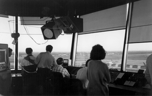
Courtesy of William J. Hughes Technical Center; FAA public domain photo.
The ISSS design calls for flexibility in how many control stations are assigned to each sector; anywhere from one to four are allowed, and the number can be changed administratively while the system is in operation. Each sector is required to have at least two controllers assigned to it. The first is the radar controller, who monitors the radar surveillance data, communicates with the aircraft, and is responsible for maintaining safe separations. The controller is responsible for managing the tactical situation in the sector. The second controller is the data controller, who retrieves information (such as flight plans) about each aircraft that is either in the sector or soon will be. The data controller provides the radar controller with the information needed about the aircraft's intentions in order to safely and efficiently guide it through the sector.
ISSS is a large system. Here are some numbers to convey a sense of scale:
• ISSS is designed to support up to 210 consoles per en route center. Each console contains its own workstation-class processor; the CPU is an IBM RS/6000.
• ISSS requirements call for a center to control from 400 to 2,440 aircraft tracks simultaneously.
• There may be 16 to 40 radars to support a single facility.
• A center may have from 60 to 90 control positions (each with one or several consoles devoted to it).
• The code to implement ISSS contains about 1 million lines of Ada.
In summary, the ISSS system must do the following:
• Acquire radar target reports that are stored in an existing ATC system called the Host Computer System.
• Convert the radar reports for display and broadcast them to all of the consoles. Each console chooses the reports that it needs to display; any console is capable of displaying any area.
• Handle conflict alerts (potential aircraft collisions) or other data transmitted by the host computer.
• Interface to the Host for input and retrieval of flight plans.
• Provide extensive monitoring and control information, such as network management, to allow site administrators to reconfigure the installation in real time.
• Provide a recording capability for later playback.
• Provide graphical user interface facilities, such as windowing, on the consoles. Special safety-related provisions are necessary, such as window transparency to keep potentially crucial data from being obscured.
• Provide reduced backup capability in the event of failure of the Host, the primary communications network, or the primary radar sensors.
In the next section, we will explore the architecture that fulfilled these requirements.
Just as an architecture affects behavior, performance, fault tolerance, and maintainability, so it is shaped by stringent requirements in any of these areas. In the case of ISSS, by far the most important driving force is the extraordinarily high requirement for system availability: less than 5 minutes per year of downtime. This requirement, more than any other, motivated architectural decisions for ISSS.
We begin our depiction of the ISSS architecture by describing the physical environment hosting the software. Then we give a number of software architecture views (as described in Chapter 2), highlighting the tactics (as described in Chapter 5) employed by each. During this discussion, we introduce a new view not previously discussed: fault tolerance. After discussing the relationships among views, we conclude the architecture picture for ISSS by introducing a refinement of the “abstract common services” tactic for modifiability and extensibility, namely, code templates.
ISSS is a distributed system, consisting of a number of elements connected by local area networks. Figure 6.5 shows a physical view of the ISSS system. It does not show any of the support systems or their interfaces to the ISSS equipment. Neither does it show any structure of the software. The major elements of the physical view and the roles its elements play are as follows:
• The Host Computer System is the heart of the en route automation system. At each en route center there are two host computers, one primary and the other ready to take over should there be some problem with the primary one. The Host provides processing of both surveillance and flight plan data. Surveillance data is displayed on the en route display consoles used by controllers. Flight data is printed as necessary on flight strip printers, and some flight data elements are displayed on the data tags associated with the radar surveillance information.
• Common consoles are the air traffic controller's workstations. They provide displays of aircraft position information and associated data tags in a plan view format (the radar display), displays of flight plan data in the form of electronic flight strips,[1] and a variety of other information displays. They also allow controllers to modify the flight data and to control the information being displayed and its format. Common consoles are grouped in sector suites of one to four consoles, with each sector suite serving the controller team for one airspace control sector.
• The common consoles are connected to the Host computers by means of the Local Communications Network (LCN), the primary network of ISSS. Each Host is interfaced to the LCN via dual LCN interface units (each called LIU-H), which act as a fault-tolerant redundant pair.
• The LCN is composed of four parallel token ring networks for redundancy and for balancing overall loading. One network supports the broadcast of surveillance data to all processors. One processor is used for point-to-point communications between pairs of processors; one provides a channel for display data to be sent from the common consoles to recording units for layer playback; and one is a spare. Bridges provide connections between the networks of the access rings and those of the backbone. The bridges also provide the ability to substitute the spare ring for a failed ring and to make other alternative routings.
• The Enhanced Direct Access Radar Channel (EDARC) provides a backup display of aircraft position and limited flight data block information to the en route display consoles. EDARC is used in the event of a loss of the display data provided by the host. It provides essentially raw unprocessed radar data and interfaces to an ESI (External System Interface) processor.
• The Backup Communications Network (BCN) is an Ethernet network using TCP/IP protocols. It is used for other system functions besides the EDARC interface and is also used as a backup network in some LCN failure conditions.
• Both the LCN and the BCN have associated Monitor-and-Control (M&C) consoles. These give system maintenance personnel an overview of the state of the system and allow them to control its operation. M&C consoles are ordinary consoles that contain special software to support M&C functions and also provide the top-level or global availability management functions.
• The Test and Training subsystem provides the capability to test new hardware and software and to train users without interfering with the ATC mission.
• The central processors are mainframe-class processors that provide the data recording and playback functions for the system in an early version of ISSS.

Each common console is connected to both the LCN and the BCN. Because of the large number of common consoles that may be present at a facility (up to 210), multiple LCN access rings are used to support all of them. This, then, is the physical view for ISSS, highlighting the hardware in which the software resides.
The module elements of the ISSS operational software are called Computer Software Configuration Items (CSCIs), defined in the government software development standard whose use was mandated by the customer. CSCIs correspond largely to work assignments; large teams are devoted to designing, building, and testing them. There is usually some coherent theme associated with each CSCI—some rationale for grouping all of the small software elements (such as packages, processes, etc.) that it contains.
There are five CSCIs in ISSS, as follows:
- Display Management, responsible for producing and maintaining displays on the common consoles.
- Common System Services, responsible for providing utilities generally useful in air traffic control software—recall that the developer was planning to build other systems under the larger AAS program.
- Recording, Analysis, and Playback, responsible for capturing ATC sessions for later analysis.
- National Airspace System Modification, entailing a modification of the software that resides on the Host (outside the scope of this chapter).
- The IBM AIX operating system, providing the underlying operating system environment for the operational software.
These CSCIs form units of deliverable documentation and software, they appear in schedule milestones, and each is responsible for a logically related segment of ISSS functionality.
The module decomposition view reflects several modifiability tactics, as discussed in Chapter 5. “Semantic coherence” is the overarching tactic for allocating well-defined and nonoverlapping responsibilities to each CSCI. The Common System Services Module reflects the tactic of “abstract common services.” The Recording, Analysis, and Playback CSCI reflects the “record/playback” tactic for testability. The resources of each CSCI are made available through carefully designed software interfaces, reflecting “anticipation of expected changes,” “generalizing the module,” and “maintaining interface stability.”
The basis of concurrency in ISSS resides in elements called applications. An application corresponds roughly to a process, in the sense of Dijkstra's cooperating sequential processes, and is at the core of the approach the ISSS designers adopted for fault tolerance. An application is implemented as an Ada “main” unit (a process schedulable by the operating system) and forms part of a CSCI (which helps us define a mapping between the module decomposition view and this one). Applications communicate by message passing, which is the connector in this component-and-connector view.
ISSS is constructed to operate on a plurality of processors. Processors (as described in the physical view) are logically combined to form a processor group, the purpose of which is to host separate copies of one or more applications. This concept is critical to fault tolerance and (therefore) availability. One executing copy is primary, and the others are secondary; hence, the different application copies are referred to as primary address space (PAS) or standby address space (SAS). The collection of one primary address space and its attendant standby address spaces is called an operational unit. A given operational unit resides entirely within the processors of a single processor group, which can consist of up to four processors. Those parts of the ISSS that are not constructed in this fault-tolerant manner (i.e., of coexisting primary and standby versions) simply run independently on different processors. These are called functional groups and they are present on each processor as needed, with each copy a separate instance of the program, maintaining its own state.
In summary, an application may be either an operating unit or a functional group. The two differ in whether the application's functionality is backed up by one or more secondary copies, which keep up with the state and data of the primary copy and wait to take over in case the primary copy fails. Operational units have this fault-tolerant design; functional groups do not. An application is implemented as an operational unit if its availability requirements dictate it; otherwise, it is implemented as a functional group.
Applications interact in a client-server fashion. The client of the transaction sends the server a service request message, and the server replies with an acknowledgment. (As in all client-server schemes, a particular participant—or application in this case—can be the client in one transaction and the server in another.) Within an operational unit, the PAS sends state change notifications to each of its SASs, which look for time-outs or other signs that they should take over and become primary if the PAS or its processor fails. Figure 6.6 summarizes how the primary and secondary address spaces of an application coordinate with each other to provide backup capability and give their relationship to processor groups.
Figure 6.6. Functional groups (FG), operational units, processor groups, and primary/standby address spaces
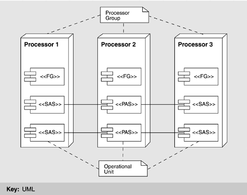
When a functional group receives a message, it need only respond and update its own state as appropriate. Typically, the PAS of an operational unit receives and responds to messages on behalf of the entire operational unit. It then must update both its own state and the state of its SASs, which involves sending the SASs additional messages.
In the event of a PAS failure, a switchover occurs as follows:
- A SAS is promoted to the new PAS.
- The new PAS reconstitutes with the clients of that operational unit (a fixed list for each operational unit) by sending them a message that means, essentially: The operational unit that was serving you has had a failure. Were you waiting for anything from us at the time? It then proceeds to service any requests received in response.
- A new SAS is started to replace the previous PAS.
- The newly started SAS announces itself to the new PAS, which starts sending it messages as appropriate to keep it up to date.
If failure is detected within a SAS, a new one is started on some other processor. It coordinates with its PAS and starts receiving state data.
To add a new operational unit, the following step-by-step process is employed:
• Identify the necessary input data and where it resides.
• Identify which operational units require output data from the new operational unit.
• Fit this operational unit's communication patterns into a systemwide acyclic graph in such a way that the graph remains acyclic so that deadlocks will not occur.
• Design the messages to achieve the required data flows.
• Identify internal state data that must be used for checkpointing and the state data that must be included in the update communication from PAS to SAS.
• Partition the state data into messages that fit well on the networks.
• Define the necessary message types.
• Plan for switchover in case of failure: Plan updates to ensure complete state.
• Ensure consistent data in case of switchover.
• Ensure that individual processing steps are completed in less time than a system “heartbeat.”
• Plan data-sharing and data-locking protocols with other operational units.
This process is not for novices, but can be navigated straightforwardly by experienced team members. A tactic discussed in a section that follows—code templates—was used to make the process more repeatable and much less error prone.
The process view reflects several availability tactics, including “state resynchronization,” “shadowing,” “active redundancy,” and “removal from service.”
Because the applications in the process view interact with each other in client-server fashion, it is reasonable to show a client-server view of ISSS as well, although the behavior it describes largely mirrors that captured by the process view shown earlier. For completeness, Figure 6.7 shows a client-server view of the system.

The clients and servers were carefully designed to have consistent (as opposed to ad hoc) interfaces. This was facilitated by using simple message-passing protocols for interaction. The result reflects the modifiability tactics of “maintaining interface stability,” “component replacement,” and “adherence to defined protocols.”
One view not discussed in Chapter 2 but which sometimes appears in architectures of large systems is the code view. A code view shows how functionality is mapped to code units.
In ISSS, an Ada (main) program is created from one or more source files; it typically comprises a number of subprograms, some of which are gathered into separately compilable packages. The ISSS is composed of several such programs, many of which operate in a client-server manner.
An Ada program may contain one or more tasks, which are Ada entities capable of executing concurrently with each other. These are the code-view corollary of the processes described in the process view. Because Ada tasks are managed by the Ada runtime system, ISSS also employs a mapping of Ada tasks onto UNIX (AIX) processes, which means that all individual threads of control (whether separate Ada programs or tasks within a single Ada program) are independent AIX processes operating concurrently.
Applications (i.e., operational units and functional groups) are decomposed into Ada packages, some of which include only type definitions and some of which are re-used across applications. Packaging is a design activity intended to embody abstraction and information hiding, and it is carried out by an operational unit's chief designer.
Underlying the operation of the ATC application programs on the ISSS processors system is a commercial UNIX operating system, AIX. However, UNIX does not provide all the services necessary to support a fault-tolerant distributed system such as ISSS. Therefore, additional system services software was added. Figure 6.8 shows as a set of layers the overall software environment in a typical ISSS processor.[2]
Figure 6.8. ISSS software architecture layers. The associations show data and/or control flow, making this an overlay of layers and a component-and-connector view.

The lowest two rows of elements above AIX represent extensions to AIX that run within the AIX kernel's address space. Because of performance requirements and for compatibility with the AIX operating system, these extensions are generally small programs written in the C language. Since they run within the kernels' address space, faults in these programs can potentially damage AIX itself; hence, they must be relatively small, trusted programs reflecting the “limit exposure” tactic, discussed in Chapter 5. Although the tactic is security based—namely, to prevent denial of service—in ISSS it is used to enhance availability, which is a complementary goal. Happily, sometimes tactics serve multiple quality attributes well.
The Atomic Broadcast Manager (ABM) plays a key role in the communication among the Local Availability Manager modules within a sector suite to manage the availability of suite functions. The Station Manager provides datagram services on the LCN and serves as the local representative of the LCN network management services. The Network Interface Sublayer provides a similar function for the point-to-point messages, sharing its network information with the Station Manager.
The next two layers represent operating system extensions that execute outside the AIX kernel's address space and therefore cannot directly damage AIX if they contain faults. These programs are generally written in Ada.
Prepare Messages handles LCN messages for application programs. Prepare BCN Messages performs a similar function for messages to be sent on the BCN. One function of these programs is to determine which of the multiple redundant copies of an application program within a sector suite is the primary and thus is to receive messages. The Local Availability Manager provides the control information needed to make this determination.
The top layer is where the applications reside. The Local Availability Manager and the Internal Time Synchronization programs are application-level system services. The Local Availability Manager is responsible for managing the initiation, termination, and availability of the application programs. It communicates with each address space on its own processor to control its operation and check its status. It also communicates with the Local Availability Manager on the other processors within its sector suite to manage the availability of suite functions, including switching from a primary to a backup copy of an application program when appropriate. The Local Availability Manager communicates with the Global Availability Management application that resides on the M&C consoles to report status and to accept control commands. The Internal Time Synchronization program synchronizes the processor's clock with that of the other ISSS processors, which is crucial to the operation of the availability management functions. (See the fault tolerance view, in Figure 6.9.)

As we said, the views listed in Chapter 2 are not exhaustive. In fact, there is no exhaustive list of views that constitute the complete software architecture for all systems or for any system. A welcome trend in software architecture is the recognition of the importance of architecture in achieving quality attributes, and therefore the importance of explicitly stating the quality attributes that the architecture is to provide. Toward this end, architects often produce views that show how the architecture achieves a particular quality attribute: a security view, for example. For runtime qualities, these views are in the component-and-connector category, showing runtime element interactions. For non-runtime qualities, these views are in the module category, showing how the implementation units are designed to achieve (for example) modifiability.
The high availability requirements for ISSS elevated fault tolerance to an important role in the design of the system. For one thing, a cold system restart in the event of a failure was out of the question. Immediate (or at least rapid) switchover to a component on standby seemed the best approach. As design progressed and this idea became clearer, a new architectural structure emerged: the fault-tolerant hierarchy (Figure 6.9). This structure describes how faults are detected and isolated and how the system recovers. Whereas the PAS/SAS scheme traps and recovers from errors that are confined within a single application, the fault-tolerant hierarchy is designed to trap and recover from errors that are the result of cross-application interaction.
The ISSS fault-tolerant hierarchy provides various levels of fault detection and recovery. Each level asynchronously
• Detects errors in self, peers, and lower levels.
• Handles exceptions from lower levels.
• Diagnoses, recovers, reports, or raises exceptions.
Each level is meant to produce another increment in system availability above that produced by the lower levels. The levels are as follows:
• Physical (network, processor, and I/O devices)
• Operating system
• Runtime environment
• Application
• Local availability
• Group availability
• Global availability
• System monitor and control
Fault detection and isolation are performed at each level in the hierarchy. Fault detection is by built-in tests, event time-outs, network circuit tests, group membership protocol, and, as a last resort, human reaction to alarms and indicators.
Fault recovery is performed at each level in the software hierarchy and can be automatic or manual. For the Local, Group, and Global Availability managers, the recovery methods are table driven. In a PAS, there are four types of recovery from failure. The type of recovery used depends on the current operational status and is determined by the Local Availability Manager using decision tables, as follows:
• In a switchover, the SAS takes over almost immediately from its PAS.
• A warm restart uses checkpoint data (written to nonvolatile memory).
• A cold restart uses default data and loses state history.
• A cutover is used to transition to new (or old) logic or adaptation data.
Redundancy is provided by network hardware (LCN, BCN, and associated bridges), processor hardware (up to four processors per processor group, redundant recording), and software (multiple address spaces per operational unit).
In addition to the availability tactics already seen with the process view, the fault tolerance view adds “ping/echo” and “heartbeat” as ways to detect failures, exception to percolate errors to the appropriate place for correction, and spare to perform recovery.
During the preceding discussion, the elements in one view made “guest appearances” in other views. Although views form the backbone of understanding a system, deeper insight is often gained by examining the relations the views have to each other and, in particular, from examining mappings from view to view. This imparts a more holistic view of the architecture.
In ISSS, CSCIs are elements in the module decomposition view. They are composed of applications, which in turn are elements in the process view and the client-server view. Applications are implemented as Ada programs and packages, shown in the code view, which in turn map to threads, which are elements in the concurrency view (not shown). The layered view describes the functionality assigned to the modules in the decomposition view in a way that shows what they are allowed to use. Finally, a specialized view focusing on the achievement of a particular runtime quality attribute—the fault tolerance view—uses the elements of the process, layer, and module views.
Chapter 9, which covers how to document a software architecture, will prescribe a special place in the documentation package for capturing view relationships. For ISSS, that mapping would include tables that list the elements from the various views and show how they correspond to each other as described above.
ISSS makes extensive use of the modifiability tactic of “configuration files,” which it calls adaptation data. Site-specific adaptation data tailors the ISSS system across the 22 en route centers in which it was planned to be deployed, and so-called preset adaptation data tailors the software to changes that arise during development and deployment but which do not represent site-specific differences. Adaptation data represents an elegant and crucial shortcut to modifying the system in the face of site-specific requirements, user-or center-specific preferences, configuration changes, requirements changes, and other aspects of the software that might be expected to vary over time and across deployment sites. In effect, the software has been designed to read its operating parameters and behavioral specifications from input data; it is therefore completely general with respect to the set of behaviors that can be represented in that data (reflecting the “generalize the module” tactic). For example, a requirements change to split the data in one ATC window view into two separate windows—a nontrivial change in many systems—could be accomplished by changing the adaptation data and a few lines of code.
The negative side is that adaptation data presents a complicated mechanism to maintainers. For example, although it is trivial (from an operational point of view) to add new commands or command syntax to the system, the implementation of this flexibility is in fact a complicated interpretive language all its own. Also, complicated interactions may occur between various pieces of adaptation data, which could affect correctness, and there are no automated or semiautomated mechanisms in place to guard against the effects of such inconsistencies. Finally, adaptation data significantly increases the state space within which the operational software must correctly perform, and this has broad implications for system testing.
Recall that the primary–secondary address space scheme described earlier relies on redundancy to achieve fault tolerance: Copies of the software are stored on different processors. While the primary copy is executing, it sends state information from time to time to all of the secondary copies so that they can take up execution when called on. The implementation plan for these copies called for both to come from true copies of the same source code. Even though the primary and secondary copies are never doing the same thing at the same time (the primary is performing its duty and sending state updates to its backups, and the secondaries are waiting to leap into action and accepting state updates), both programs come from identical copies of the same source code. To accomplish this, the contractor developed a standard code template for each application; the template is illustrated in Figure 6.10.
The structure is a continuous loop that services incoming events. If the event is one that causes the application to take a normal (non-fault-tolerant-related) action, it carries out the appropriate action, followed by an update of its backup counterparts' data so that the counterpart can take over if necessary. Most applications process between 50 and 100 normal events. Other events involve the transfer (transmission and reception) of state and data updates. The last set of events involves both the announcement that this unit has become the primary address space and requests from clients for services that the former (now failed) primary address space did not complete.
This template has architectural implications: It makes it simple to add new applications to the system with a minimum of concern for the actual workings of the fault-tolerant mechanisms designed into the approach. Coders and maintainers of applications do not need to know about message-handling mechanisms except abstractly, and they do not need to ensure that their applications are fault tolerant—that has been handled at a higher (architectural) level of design.
Code templates represent a refinement of the “abstract common services” tactic; the part of each application that is common is instantiated in the template. This tactic is related to several other tactics for modifiability. It reflects an “anticipation of expected changes” in the parts it leaves variable and it gives the processes a “semantic coherence,” because they all do the same thing when viewed abstractly. The template lets programmers concentrate on the details of their application, leading to “generalizing the module.” And by making the interfaces and protocols part of the template, they “maintain interface stability” and achieve “adherence to defined protocols.”
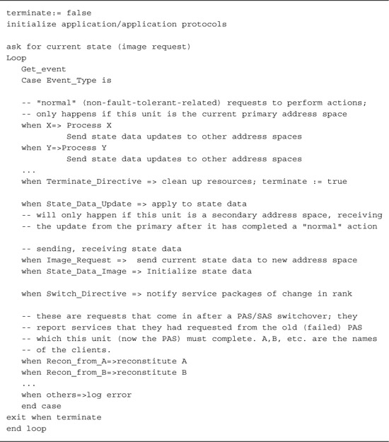
Table 6.1 summarizes the approaches and tactics by which the ISSS software architecture met its quality goals.

[1] A flight strip is a strip of paper, printed by the system that contains flight plan data about an aircraft currently in or about to arrive in a sector. Before ISSS, these flight strips were annotated by hand in pencil. ISSS was to provide the capability to manipulate strips onscreen.
[2] Strictly speaking, Figure 6.8 is an overlay between a layered view and a component-and-connector view, because it shows runtime connections between the submodules in the layers. In two cases, AAS Services and Other Device Driver, the connections among these and other submodules within the layered view are not shown, because there are so many that it would clutter the diagram. These services are freely used by most of the layered system. The actual connections would be listed in the supporting documentation for this view.
Like all of the case studies in this book, ISSS illustrates how architectural solutions can be the key to achieving the needs of an application. Table 6.1 summarized the key approaches used. Because of its projected long life, high cost, large size, important function, and high visibility, ISSS was subject to extraordinary change pressures over and above its demanding operational requirements. Human–computer interfaces, new hardware, new commercial components, operating system and network upgrades, and capacity increases were not just likely but foregone conclusions. The architecture, by using a wide range of fault tolerance mechanisms (and code templates), including hardware and software redundancy and layered fault detection, and by using distributed multiprocess computing with client-server message passing, was able to satisfy its complex, wide-ranging operational requirements.
A footnote to our story is the intensive software audit that was carried out on the ISSS architecture by a blue-ribbon panel of experts when the U.S. government was considering abandoning ISSS in favor of a simpler, less expensive solution. The audit assessed the architecture's ability to deliver the required performance and availability and included modifiability exercises that walked through several change scenarios, including the following:
• Making major modifications to the M&C position's human–computer interface
• Importing third-party-developed air traffic applications into the ISSS system
• Adding new ATC views to the system
• Replacing the RS/6000 processors with a chip of similar capability
• Deleting electronic flight strips from the requirements
• Increasing the system's maximum capacity of flight tracks by 50 percent
In every case, the audit found that the ISSS software architecture had been designed so that the modifications would be straightforward and, in some cases, almost trivial. This is a tribute to its careful design and its explicit consideration of quality attributes and the architectural tactics to achieve them.
The saga of the FAA's attempts to upgrade its air traffic control software has been written about extensively; for example, by [Gibbs 94]. The effort to audit the ISSS system for salvageability was reported by [Brown 95]. In these papers, maintainability is treated as a dual quality related not only to the properties of the system but also to the capabilities of the organization slated to perform the maintenance. This important aspect of maintainability—the necessary fit between the maintenance that a system needs and the maintenance that an organization is prepared to provide for it—is not usually discussed.
1. High availability was a main impetus behind the architecture presented in this chapter. How were other quality attributes, such as performance, affected by this requirement? How might the architecture change if this requirement were removed?
2. How many architectural patterns can you recognize in the architecture for ISSS?
3. Construct quality attribute scenarios, as described in Chapter 4, for as many of the requirements given in Section 6.2 as you can. Where necessary information is missing, propose reasonable substitutions.