
Appendix D
Formulae for Simple Radiating Structures
This appendix provides closed-form expressions for calculating radiated fields from wire structures, as often found in PCBs with attached cables. A method for considering also the metallic reference plane of a semi-anechoic chamber for measurements is given. A low-frequency approximation method for computing radiated fields from an aperture is introduced and explained for the case of a rectangular aperture.
D.1 Wire Structures
Formulae for calculating the radiated E-field in the Far-Field (FF) region when the currents on the wires are known are shown in Table D.1. It is important to make the following observations:
- Infinitesimal dipole. In general, the EM fields radiated by an infinitesimal dipole have components in spherical coordinates that depend on 1/r, 1/r2, and 1/r3 [1]. However, as the interest is focused on E-field prediction at a distance r ≥ 3 m, where the observation point is normally in the far-field region, the expression for the E-field can be simplified and becomes dependent on 1/r only, as shown in Table D.1. Note that, in the far field, E and H are mutually orthogonal and E/H = 377Ω.
- Electrically short differential-mode structure. As a first consequence of using the far-field approximation for an infinitesimal dipole, the simple expression in Table D.1 is obtained for the case of two parallel electrically short wires with opposite currents. This is a practical case of signal current and its return path. Note that the E-field depends on f2.
- Electrically short common-mode structure. When the two parallel wires have the same current in amplitude and sign, the expression for E depends on f. For example, this is the case for a PCB where the ground plane is absent and the signal current flowing on a wire returns through another parallel wire. It is a very dangerous case, because common-mode currents of some μA can produce a radiated field above the limit of emission required by the standards.
Table D.1 Formulae for calculating the radiated E-field from wire structures
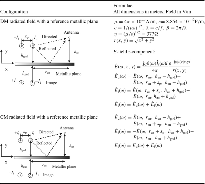
Table D.2 Formulae for differential-mode and common-mode emissions produced by wire structures in the presence of a metallic reference plane
- Long wire. This is a particular case of a more general structure in which, once the current distribution is known, the field can be computed by segmenting the structure into several electrically short dipoles. The resulting field at the observation point is determined as the sum of all the individual dipole contributions. The number of segments is dictated by the maximum frequency of interest. Note that, for a long wire and angle ϑ0 = 90°, the expression to be used is the same as for an infinitesimal dipole in which the distance r(ξ) is replaced by r0, that is, the distance between the central point of the antenna and the observation point. The average current
 is assigned to the generic current
  .
.

D.2 Wires and Ground Planes
Very often the calculation of the radiated field from a PCB with an attached cable is required when a reference ground plane is present. This is the case when the models are to reproduce radiated emission measurements performed in a semi-anechoic chamber for EMC limit compliance. Differential-mode emission occurs in a case of two parallel wires or in case of a wire above a PCB ground plane. For a radiating structure like this, the image method can be applied twice: once for the PCB structure and once for the PCB and metallic floor of the semi-anechoic chamber. The method consists in replacing the ground plane with an image conductor parallel to the signal conductor at a distance twice that between the signal conductor and the ground plane. This operation results in the two cases depicted in Table D.2. For both cases the expression for long wire must be applied 4 times, considering the directions of the currents and the distance of the signal and image wires from the observation point (usually the location of the antenna for measurements).
Table D.3 Formulae for calculating the radiation from apertures in a shielded box

D.3 Emission from Apertures
Especially for complex digital equipment consisting of several PCBs connected by motherboards and cables, the solution of shielding the equipment is adopted to mitigate radiated emission. Unfortunately, apertures are necessary for cooling, and the apertures become sources of emission excited by the fields produced by the internal circuits. Generally, the computation of these fields is a complicated process and full-wave codes are required. However, when the maximum dimension of the aperture is electrically short, or less than the wavelength at the maximum frequency of interest, the analytical method illustrated in Table D.3 can be adopted [2]. The starting point is that an electrically small loop with constant current ![]() radiates as a small magnetic dipole of moment
radiates as a small magnetic dipole of moment ![]() . It can be shown that an electrically short aperture radiates as an electric (perpendicular to the aperture) and two magnetic dipoles (orthogonal to and on the plane of the aperture). The dipole moment is determined by the geometrical dimensions, as discussed in Section 9.8.2. The structure with a rectangular aperture shown in Table D.3 is a particular case where the circuit within the shielded box produces in the aperture an electric field oriented as the y axis and a magnetic field oriented as the x axis. In this situation, the magnetic dipole moment
. It can be shown that an electrically short aperture radiates as an electric (perpendicular to the aperture) and two magnetic dipoles (orthogonal to and on the plane of the aperture). The dipole moment is determined by the geometrical dimensions, as discussed in Section 9.8.2. The structure with a rectangular aperture shown in Table D.3 is a particular case where the circuit within the shielded box produces in the aperture an electric field oriented as the y axis and a magnetic field oriented as the x axis. In this situation, the magnetic dipole moment ![]() only is present. The radiated field from the aperture in the far field can be calculated using the expression for the small loop, where
only is present. The radiated field from the aperture in the far field can be calculated using the expression for the small loop, where ![]() is directly proportional to the coefficient αm,xx which depends on the minimum w and maximum l dimension of the aperture.
is directly proportional to the coefficient αm,xx which depends on the minimum w and maximum l dimension of the aperture.
For generic orientation of the EM incident fields on the aperture, magnetic dipole moments ![]() and
and ![]() along the x and y axes, respectively, and the electrical dipole moment
along the x and y axes, respectively, and the electrical dipole moment ![]() along the z axis are present. The link with the incident fields on the aperture are coefficients tabulated according to the type of aperture [2].
along the z axis are present. The link with the incident fields on the aperture are coefficients tabulated according to the type of aperture [2].
References
1. Balanis, C.,‘Antenna Theory: Analysis and Design’, 2nd edition, John Wiley & Sons, Inc., New York, NY, 1997.
2. Tesche, F., Ianoz, M., and Karlsson, T., ‘EMC Analysis Methods and Computational Models’, John Wiley & Sons, Inc., New York, NY, 1997.
Signal Integrity and Radiated Emission of High-Speed Digital Systems Spartaco Caniggia and Francescaromana Maradei
© 2008 John Wiley & Sons, Ltd