
Piezoelectric transducers for assessing and monitoring civil infrastructures
Y.-K. An, Southeast University, China
M.K. Kim and H. Sohn, Korea Advanced Institute of Science and Technology (KAIST), Republic of Korea
Abstract:
Piezoelectric transducers are being commonly used for sensing and actuation applications for smart structural systems. In particular, they are widely used for structural health monitoring (SHM) thanks to such attractive characteristics as multi-functionality, nonintrusivity, light weight, low cost, rapid response time, and high repeatability. This chapter first deals with the basic principles of piezoelectric transducers and the characteristics of piezoelectric materials. Subsequently, various piezoelectric transducer-based SHM methodologies including guided wave, impedance, and acoustic emission techniques are summarized. Then, their state-of-the-art applications to SHM fields are presented. Future trends are also discussed in this chapter.
Key words
piezoelectric transducers; structural health monitoring; guided wave; impedance; acoustic emission
4.1 Introduction
This chapter deals with the characteristics of piezoelectric materials, the basic principles of the piezoelectric transducer, and its state-of-the-art applications. In particular, there is focus on applications of the piezoelectric transducers to SHM fields.
Over the last several decades, piezoelectric transducers have been widely used for sensing and actuation applications in smart structural systems, thanks to their versatility. The key characteristic of the piezoelectric transducer is piezoelectricity. When a piezoelectric material is squeezed or stretched, an electric charge is generated across the material, which is called ‘direct piezoelectricity.’ Conversely, a piezoelectric material mechanically deforms when subjected to electric voltage, which is called ‘converse piezoelectricity’ (Cady, 1964).
The piezoelectricity phenomenon was first discovered by brothers, Pierre and Jacques Curie in 1880 (Curie and Curie, 1880). While investigating the characteristics of a number of natural crystals, they realized that some materials, such as quartz and tourmaline, have an ability to transform energy of a mechanical input into an electrical output. This unique characteristic of the piezoelectric materials have been widely applied to various fields. In the early 1900s, several breakthroughs were made. In 1917, Langevin developed a piezoelectric transducer composed of a quartz and steel sandwich for ultrasonic generation (Jan et al., 2010). In 1921, Cady proposed the piezoelectric resonator as an electrical oscillator to achieve frequency stability (Cady, 1922). This piezoelectric resonator made a great contribution in the field of broadcasting systems. Further applications of piezoelectric materials include watches, crystal and ceramic filters, underwater acoustic devices, and speakers (Jan et al., 2010). In recent years, the application fields of piezoelectric transducers have been widened into SHM (Staszewski et al. , 2004a; Balageas et al., 2006; Boller et al., 2009).
4.2 Principle of piezoelectricity
This section first introduces the basic principles of piezoelectricity and piezoelectric materials.
4.2.1 Definition and categorization of piezoelectricity
Electric charge is created between two electrodes of piezoelectric materials when the materials are exposed to an external mechanical strain. On the other hand, when voltage is applied to the piezoelectric materials, it expands or contracts, creating mechanical strain. The former effect is called the direct piezoelectric effect, as shown in Fig. 4.1a, and the latter is the converse piezoelectric effect, as described in Fig. 4.1b. Based on these unique characteristics of piezoelectric materials, various types of actuators and sensors have been developed.

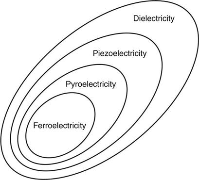
The piezoelectricity can be categorized as shown in Fig. 4.2 (Zhang et al., 2009). Dielectricity is defined as the characteristic where dipoles within an insulated material can be polarized when an electric field is applied. The piezoelectricity as a subgroup of dielectricity is the material property where the polarization can be changed by mechanical perturbation. As a subgroup of piezoelectricity, the polarization of pyroelectric materials can be altered by temperature variation. Finally, ferroelectricity is the material characteristic in which spontaneous polarization can exist with zero electric field, once polarization is achieved by a sufficiently strong electric field (Damjanovic, 1998).
Although ferroelectricity is a subgroup of dielectricity, polarization behavior is different. Figure 4.3 conceptually compares the polarizations of dielectric and ferroelectric materials under a varying electric field. The polarization of the dielectric material shows a linear relationship with the electric field, as shown in Fig. 4.3a. Here, P and E denote the polarization and electric field, respectively. On the other hand, the ferroelectric materials show a hysteresis behavior under the changing electric field, as shown in Fig. 4.3b. The electric field is applied to the ferroelectric material until the maximum polarization (Pmax) is achieved. Then, the material exhibits a remanent polarization (Pr) even when the electric field is removed. To eliminate Pr, a reverse electric field is applied in the opposite direction. This hysteresis nature of ferroelectric materials has been widely employed for nonvolatile memories (Bertotti and Mayergoyz, 2005). The information is stored when the polarization is in positive or negative remanent polarized state, and the stored information is kept before the reverse electric field is applied.

4.2.2 Operational principle of piezoelectric materials
The operational principle of piezoelectric materials depends on the direction of applied external loads to the piezoelectric materials. Figure 4.4 displays three different effects, i.e. longitudinal, transverse, and volume effects (Jon, 2005). For these three effects, the relationships between the induced charge (Q) and the applied longitudinal force (FL), transverse force (FT), and volumetric pressure (P) can be summarized as follows, respectively:
[4.1]
 [4.1]
[4.1]

where dL is the longitudinal piezoelectric coefficient and dT is the transverse piezoelectric coefficient. AQ and AF are the surface areas where Q and FT are applied, respectively.
For the longitudinal effect, the induced charge (QL) and the applied longitudinal force (FL) share the same surface as shown in Fig. 4.4a. Thus, QL is proportional to FL. For the transverse effect, the transverse force (FT) is applied to the perpendicular surface of QT as shown in Fig. 4.4b, and QT becomes proportional to the product between FT and the surface ratio (RS). For the volume effect shown in Fig. 4.4c, the volumetric coefficient depends on the combination of the longitudinal and transverse coefficients when the pressure (P) is applied to all surfaces of the element. These three effects are used independently or collectively to manufacture various types of piezoelectric transducers. For example, the longitudinal and shear effects are utilized for manufacturing surface-mounted pressure and shear wave transducers, respectively (Jon, 2005).
4.2.3 Constitutive equations of piezoelectric materials
The piezoelectric constitutive relations between the electrical and mechanical parameters are expressed as follows (IEEE Standard, 1987):
[4.2]
[4.3]
where Di is the electric displacement (C/m2), Sk is the strain, Ej is the applied electric field (V/m), and Tm is the stress (N/m2). Here ![]() and SEkm denote the dielectric permittivity (F/m) and the elastic compliance (m2/N), respectively. The superscripts T and E denote that these quantities are measured at zero stress and zero electric field, respectively. Then, ddim and dcjk are the piezoelectric coefficients (C/N or m/V), respectively. Here, the superscripts c and d represent the converse and direct piezoelectric effects, respectively, and ddim and dcjk are numerically identical. For a typical sheet of piezoelectric material, the poling direction is usually along the thickness (3-axis), and the 2- and 3-axes denote the plane of the sheet, as shown in Fig. 4.5.
and SEkm denote the dielectric permittivity (F/m) and the elastic compliance (m2/N), respectively. The superscripts T and E denote that these quantities are measured at zero stress and zero electric field, respectively. Then, ddim and dcjk are the piezoelectric coefficients (C/N or m/V), respectively. Here, the superscripts c and d represent the converse and direct piezoelectric effects, respectively, and ddim and dcjk are numerically identical. For a typical sheet of piezoelectric material, the poling direction is usually along the thickness (3-axis), and the 2- and 3-axes denote the plane of the sheet, as shown in Fig. 4.5.

The constitutive relations can be rewritten in a matrix form (Sirohi and Chopra, 2000):
[4.4]
The applied electric field matrix E and the corresponding electric displacement matrix D are
[4.5]
 [4.5]
[4.5]
where Di denotes the electric displacement in the i direction when the electric field Ej is applied in the j direction.
Then, the permittivity matrix εT is
[4.6]
 [4.6]
[4.6]
where the electric permittivities εT11, εT22, and εT33 denote the measurement of the polarizability in the 1, 2, and 3 directions, respectively, when an electric field is applied in the corresponding directions.
The d matrix can be expressed as
[4.7]
 [4.7]
[4.7]
where the piezoelectric coefficients d31, d32, and d33 represent the normal strains in the 1, 2, and 3 directions due to the electrical poling in the 3 direction (E3), respectively. The coefficients d15 and d24 are the shear strain in the 1–3 plane due to the field E1 and the shear strain in the 2–3 plane due to the field E2, respectively.
The stress and strain matrices, T and S, can be written as
[4.8]
 [4.8]
[4.8]
where σ1 σ2, and σ3 are the normal stresses, and S1, S2, and S3 are the corresponding normal strains. σ4, σ5, and σ6 are the shear stresses in the 2–3, 3–1, and 1–2 planes, and S4, S5, and S6 represent the corresponding shear strains, respectively.
The compliance matrix SE is
[4.9]
 [4.9]
[4.9]
where the six elastic compliances from S11 to S33 denote the ratio of the normal strain to the normal stress in each direction under a constant electric field, respectively. For example, s12 is the ratio of the normal strain in the 2 direction to the normal stress in the 1 direction. The remaining three elastic compliances from s44 to s66 indicate the ratio of the shear strain to the shear stress in each direction.
Equation [4.2] is a sensing equation representing the direct piezoelectric effect, while Equation [4.3] is an actuating equation corresponding to the converse piezoelectric effect. Based on these constitutive equations, sensors and actuators are analytically modeled. Then, the analytical models can be used to fabricate and optimize piezoelectric transducers and to simulate their effects for actuation or sensing applications (Roundy and Wright, 2004; Park et al., 2010a).
4.3 Piezoelectric materials and the fabrication of piezoelectric transducers
Now, the characteristics of piezoelectric materials and the fabrication process of piezoelectric ceramics are described in this section.
4.3.1 Piezoelectric materials
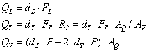
Natural piezoelectric materials such as quartz (SiO2) and Rochelle salt (NaKC4H4O6–4H2O) have been widely used for piezoelectric transducers. Quartz, shown in Fig. 4.6a, has been the most favorable material for many years, and is still popular for pressure measurement because of its high mechanical strength of 2–3 GPa, high-voltage sensitivity, and thermal resistance up to 400 °C (Jon, 2005). Rochelle salt is also used to manufacture various types of transducers due to its high piezoelectricity. However, its applications are often limited due to its vulnerability to liquid and high temperature.
To overcome the limitations of these natural piezoelectric materials and improve the piezoelectric performance, synthesized piezoelectric materials have been developed for the last two decades. For example, piezoelectric ceramics such as barium titanate (BaTiO3), lead titanate (PbTiO3), and lead zirconate titanate (PZT) (PbZrTiO3) exhibit much higher piezoelectric and piezoelectric voltage constants than quartz, making them attractive for transducer manufacturing. Table 4.1 compares the material properties between APC850-type PZT and quartz (American Piezo Ceramics Inc.). Other widely used synthesized piezoelectric materials include lithium niobate (LiNbO3) and lithium tantalite (NiTaO3), which have the characteristics of insolubility and thermal resistance up to 650 °C. Moreover, these materials have high electro-mechanical coupling factors compared to natural piezoelectric materials. Thus, they have been widely used for surface acoustic wave devices (Ikeda, 1996).
Table 4.1
Typical properties of piezoelectric ceramic (American Piezo Ceramics Inc.)
| Property | Symbol | APC850-type PZT | Quartz |
| Curie point(°C) | Tc | 360 | 573 |
| Elastic modules (1010 N/m) | YE | 6.3 | 7.7 |
| Dielectric constant (Unitless) | ε/ε0 | 1200 | 4.5 |
| Piezoelectric constant (pC/N) | d | 175 | 2.3 |
| Piezoelectric voltage constant (Vm/N) | g | 12.4 | 0.5 |
| Electromechanical coupling factor (Unitless) | k | 0.36 | 0.10 |
| Frequency constant (Hz.m) | N | 1500 | 2800 |
| Poisson ratio (Unitless) | υ | 0.35 | 0.17 |
| Density (kg/m3) | ρ | 7600 | 2650 |

4.3.2 Fabrication of piezoelectric ceramics
The fabrication of the piezoelectric ceramics starts with mixing raw materials such as lead oxide (PbO), zirconium (Zr), and titanium (Ti) with chemically correct proportions. Then, the mixture is heated around 800–1000 °C to accelerate the reaction of the components (Sirohi and Chopra, 2000). This blending and heating process creates the piezoelectric powder. Subsequently, the piezoelectric powder is mixed with a binder and sintered into the desired shape, resulting in the ceramic material. After this material is cooled down, the crystalline structure is formed. Then, conductive electrodes are bonded to the ceramic surface. Here, metallic silver is commonly used as the electrode (Jaffe, 1971).
Next, the poling process is performed, as shown in Fig. 4.7. The crystalline material, which has randomly oriented dipoles, is warmed up slightly below its Curie temperature as shown in Fig. 4.7a (Fraden, 1996). Then, an electric field is applied to the unit cell so that the dipoles strongly align along the electric field lines, as shown in Fig. 4.7b. Finally, the material is cooled down while the electric field is maintained, and the electric field is removed. Figure 4.7c shows that the polarization permanently remains as long as the poled material is maintained below the Curie temperature. Note that if excessive mechanical stress, large input voltage, or high temperature over the Curie temperature is applied to the material, it can lose its polarization.

4.4 Piezoelectric transducers for SHM applications
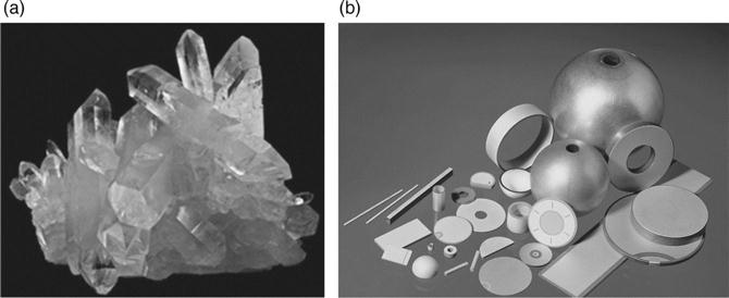
This section deals with various types of piezoelectric transducers used for SHM applications as displayed in Fig. 4.8. PZT shown in Fig. 4.8a is one of the most widely utilized transducer types for SHM applications, because of its light weight, low cost, and a fast electromechanical response. However, PZT has limited conformity to curved surfaces due to its brittleness. To overcome this limitation, flexible piezoelectric polymers and composites have been developed.
Macro-fiber composite (MFC) is an innovative flexible transducer offering high-performance at a competitive cost. MFC was first developed at NASA Langley Research Center in 1996 to enhance the flexibility of piezoelectric transducers, as shown in Fig. 4.8b (High and Wilkie, 2003). Figure 4.9a shows the structure of MFC composed of rectangular fibers sandwiched between adhesive layers and electrode polyimide films (Smart Materials Inc.). With great flexibility, MFCs were used as a guided wave generator in a pipeline structure (Lee and Sohn, 2012). In addition, Wait and Todd (2007) utilized MFCs as a strain sensor through dynamic strain tests on an aluminum specimen.

Another widely used flexible piezoelectric transducer is active fiber composite (AFC) developed by Massachusetts Institute of Technology (Bent et al., 1995). Figure 4.9b depicts the structure of AFC composed of thin and conformable piezoelectric fibers with orthotropic materials. It was initially developed for actuators for structural control, but it also has been used for SHM applications. Williams et al. (2002) used AFCs to suppress the vibration of helicopter rotor blades, and Birchmeier et al. (2009) investigated the generation of the fundamental Lamb wave modes using AFCs.
An integrated network of distributed piezoelectric transducers, called the ‘smart layer,’ has been introduced by Lin and Chang (2002). The smart layer is a thin dielectric film with embedded piezoelectric transducers, as shown in Fig. 4.8c. Since the smart layer is fabricated using thin and flexible printed circuits, it can also be used for curved surface structures or complex structures. Qing et al. (2007) utilized the smart layer for monitoring of a composite bottle structure.
Polyvinylidene fluoride (PVDF) is another popular piezoelectric polymer because of its flexibility. PVDF developed by Kawai has been employed for SHM applications including curved structures and high-strain spots (Kawai, 1969). Lin and Giurgiutiu (2006) applied PVDF to a long rod for ultrasonic measurement, and Yi and Liang (2008) utilized PVDF for the deformation measurement of automotive tires. Matsumoto et al. (2004) utilized PVDF as a strain sensor to evaluate the surface strain distribution of a rectangular plate. Table 4.2 compares the material properties of PVDF and other typical piezoelectric materials. Since the piezoelectric voltage constant of PVDF is much higher than those of the other materials, it is frequently used for headphones and speakers. However, PVDF is generally not suitable for actuation, due to its relatively small elastic modulus. Thus, it is generally limited to sensing applications (Sirohi and Chopra, 2000; Lin and Giurgiutiu, 2006). In addition, its performance highly depends on thermal and poling conditions.
Table 4.2
Properties of piezoelectric materials at 20 °C
| Property | PVDF | PZT | BaTiO3 | Quartz |
| Density (103 kg/m3) | 1.78 | 7.5 | 5.7 | 2.65 |
| Dielectric constant (Unitless) | 12 | 1200 | 1700 | 4.5 |
| Elastic modules (1010 N/m) | 0.3 | 8.3 | 11 | 7.7 |
| Piezoelectric voltage constant (Vm/N) | 216 | 10 | 5 | 0.5 |
| Piezoelectric constant (pC/N) | 20 | 110 | 78 | 2.3 |
| Electromechanical coupling constant (%) | 11 | 30 | 21 | 10 |
| Acoustic impedance (106 kg/m2s) | 2.3 | 25 | 25 | 14.3 |

Source: Reproduced from Giurgiutiu, 2008.
Another newly developed piezoelectric transducer is the polymer-based piezoelectric paint sensor, as shown in Fig. 4.10a. The piezoelectric paint sensor developed by Klein et al. (1986) is composed of tiny piezoelectric composite films. The benefits of the piezoelectric paint sensors are compactness, flexibility, and controllability of piezoelectric properties. White et al. (2004) investigated the applicability of the piezoelectric paints as vibration sensors, and Zhang (2006) employed the piezoelectric paints for fatigue crack detection.

Smart aggregate is a new piezoceramic device developed for concrete structure monitoring as shown in Fig. 4.10b (Song et al., 2008). The smart aggregate is composed of a waterproof piezoelectric patch with lead wires embedded in a small concrete block. The devices are then embedded in concrete structures during casting. One smart aggregate is used as an actuator to generate a desired input signal, while the other smart aggregates are used as sensors to detect the corresponding responses. They are used for early-age strength monitoring (Gu et al., 2006), crack detection (Song et al., 2007a), and impact detection and evaluation (Song et al., 2007b).
4.5 Bonding effects
Figure 4.11 shows the bonding layer between the piezoelectric transducer and the host structure. In typical SHM applications, the piezoelectric transducers are assumed to be perfectly bonded with a host structure via an adhesive. In reality, however, the adhesive forms an interfacial layer of finite thickness between the piezoelectric element and the host structure, and this adhesive layer significantly affects the shear stress (r) transfer between the transducer and the host structure (Rabinovitch and Vinson, 2002). Crawley and de Luis (1987) first proposed a shear spring model of the adhesive effect. Their analytical model assumed that the shear stress in the adhesive is proportional to the longitudinal relative deformation between the piezoelectric transducer and the host structure. The shear lag effect becomes more dominant with a lower shear modulus and a thicker adhesive layer, resulting in less effective shear transfer between the piezoelectric transducer and the host structure. Bhalla and Soh (2004) formulated electromechanical impedance considering the shear lag effect, and Qing et al. (2006) experimentally investigated the effects of adhesive thickness and its modulus on the performance of bonded piezoelectric elements. Sohn and Lee (2010) tuned the conventional Lamb wave tuning curve analyzing the bonding layer effect.

4.6 Limitations of piezoelectric transducers
Piezoelectric transducers generally have limited temperature of operation, maximum applicable voltage without causing depolarization, and mechanical strain that the transducers can measure or mechanically sustain. Around 200–300 °C, phase transition of piezoelectric materials occurs, resulting in the loss of piezoelectricity (Akiyama et al, 2009). For instance, it is reported that polycrystalline (Bi4Ti3O12) loses its piezoelectricity around 675 °C by the depolarizing phenomenon (Damjanovic, 1998). The piezoelectric transducers can also be depolarized when a strong electric field, about 500–1000 V/mm, is applied with the polarity opposite to the original poling direction (Piezo Systems Inc. (2013)). Piezoelectric transducers also have their maximum measurable strain level, normally 500μ (Piezo Systems Inc.). In reality, piezoelectric transducers attached on a target structure are often exposed to high-stress and -strain concentrations under operating conditions of the target structure.
4.7 SHM techniques using piezoelectric transducers
This section extensively summarizes piezoelectric transducer based on various SHM methodologies including guided wave, impedance, acoustic emission, and self-diagnosis techniques.
4.7.1 Guided wave techniques
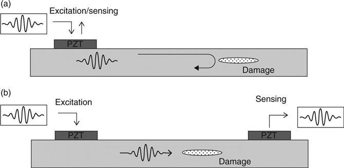
Guided wave techniques using piezoelectric transducers are one of the most popular SHM techniques. These techniques are attractive because guided waves, defined as elastic waves confined by the boundaries of a structure, can travel a long distance with little signal attenuation and high sensitivity to small structural damages (Cawley and Alleyne, 1996; Staszewski et al, 2004a). Figure 4.12 depicts two typical modes of guided wave measurement (Raghavan and Cesnik, 2007). When an electrical voltage is applied to PZT mounted on a plate-like target structure, guided waves are generated and propagate along the target structure. Then, the corresponding responses can be measured by the same PZT in a pulse–echo mode or by the other PZT in a pitch–catch mode. The guided waves traveling through a structural discontinuity produce scattering, reflection, and mode conversion, making it possible to identify structural damage. Alleyne and Cawley (1992) investigated the interactions of guided waves with a variety of structural damage through finite element analysis and experiment. Then, Rose (1999) theoretically estimated the quantity of guided wave mode conversions produced by thickness variations of waveguides.
Guided waves are, however, also sensitive to environmental and operational variation, often resulting in false alarms (Sohn, 2007). To minimize these effects on the guided wave techniques, reference-free guided wave techniques have been proposed. In conventional guided wave techniques, structural damage is often identified by simple comparison between baseline data obtained from the pristine condition of the target structure and the current data measured from current state of the target structure. On the other hand, the reference-free techniques utilize only current data for damage diagnosis, thus making them less sensitive to environmental and operational variations.
One of the first proposed reference-free techniques is based on a time reversal process (TRP). The basic assumption of the TRP method is that the elastodynamic reciprocity is broken when damage occurs along a guided wave propagating path. Park et al. (2006a) and Sohn et al. (2007) developed the TRP-based damage detection techniques and applied them to composite structures. Kim and Sohn (2007) proposed another reference-free technique based on the polarization characteristics of piezoelectric transducers. This reference-free technique identifies cracks by extracting crack-induced mode conversion signals using PZT transducers attached to both sides of a thin metal plate. Sohn and Kim (2010) also developed a reference-free technique using newly designed dual PZT transducers so that mode conversion signals can be isolated using the PZT transducers attached only to a single surface of a target structure. Then, An and Sohn (2010) examined the performance of the reference-free techniques under varying temperature and external loading conditions.
Guided wave imaging techniques using piezoelectric transducers have been developed for damage localization as well as identification. In order to construct guided wave images, guided wave tomography techniques, using the data obtained from a sparse array of piezoelectric transducers, have been developed. Hutchins et al. (1993) detected defects in aluminum plates by constructing guided wave tomography images using noncontact air coupled and electromagnetic acoustic transducers. Leonard et al. (2002) used the guided wave tomography technique to construct a quantitative Lamb wave map. This tomography technique, however, requires solution of a complex inverse problem to build a guided wave image with high spatial resolution.
Another guided wave imaging technique is a phased array technique. It employs a dense transducer array that can sequentially generate guided waves to obtain guided wave images based on interference patterns. Figure 4.13 shows an example of beam forming toward a specific direction using a phased array. This technique can identify and localize damage in a wide area by adjusting the excitation time delay. Giurgiutiu and Bao (2004) utilized the phased arrays to localize damages in thin-wall structures, and Banchet et al. (2004) used phase arrays to detect crack defects in a lap joint structure. Fromme et al. (2006) proposed a prototype phased array to detect corrosion damage in large plate-like structures. Luo and Rose (2007) used a phase array focusing method to perform pipe inspection. This method shows an improved signal-to-noise ratio and better sensitivity that enables detection of small defects in pipeline network. However, the use of this phase array technique is often limited, because the instrumentation is expensive and performance of the whole system is governed by each piezoelectric transducer of the system.

4.7.2 Impedance techniques
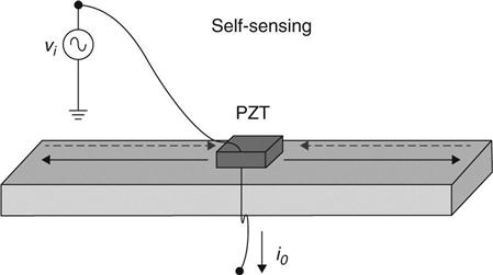
Impedance techniques using piezoelectric transducers have been developed to detect local damages in complex structures (Liang et al., 1994). In the impedance technique, an electromechanical impedance signal is measured by applying an electric voltage to PZT and measuring the corresponding output current when the PZT is attached to a host structure, as shown in Fig. 4.14. Since the electrical impedance of the PZT is coupled with the mechanical impedance of the host structure, potential damage can be manifested by monitoring the change of the measured impedance signal. The electromechanical impedance can be written as follows:
[4.10]
where Ztotal is the electromechanical impedance measured by the PZT, Zs is the mechanical impedance of the host structure, Za is the mechanical impedance of the PZT, ω is angular frequency, C is the zero-loaded capacitance of the PZT, and k31 is the electromechanical coupling coefficient of the PZT, respectively.
The impedance technique is attractive for local damage detection because it is sensitive to even small damage and can be applied to complex structures (An et al., 2012). However, impedance measurements become difficult with highly damped materials such as carbon fiber reinforced polymer (CFRP) and glass fiber reinforced polymer (GFRP) or large-scale structures with high mechanical impedance, because PZT transducers cannot produce excitation forces large enough to create standing waves, which are a requisite to obtain impedance signal (Kim et al., 2011a).
A number of PZT-based impedance SHM applications have been reported. For crack detection, several numerical and experimental studies have been successfully carried out (Giurgiutiu, 1999; Soh et al., 2000; Park et al., 2006b). For bolt loosening detection, bolt joint connections of airplane and bridge structures have been investigated (Chaudhry et al., 1995; Min et al., 2010a). For delamination detection, a few numerical and experimental implementations have been conducted on composite structures (Bois and Hochard, 2004; Yan et al., 2011). It is worth noting that the sensitivity of the impedance technique to each damage type is different. An and Sohn (2011) investigated the sensitivity of the impedance technique to three different types of damages, i.e., crack, bolt loosening, and delamination.
In the impedance technique, one of the most challenging issues is that the impedance signals are also sensitive to environmental variations, such as temperature and loading changes as well as structural damages. To minimize these effects, temperature compensation techniques have been developed by several researchers. Temperature variation often causes a horizontal frequency shifting of impedance signals, and this temperature induced shifting is compensated by Koo et al. (2009) using a cross-correlation coefficient. Lim et al. (2011) also proposed a data normalization technique using Kernel principal component analysis to minimize false alarms caused by temperature and static/dynamic loading variations. Furthermore, Kim et al. (2011b) proposed reference-free impedance technique for crack detection in plate-like structures. This reference-free technique identifies cracks by extracting converted modes from the impedance signals measured from only current state of the target structure, thus making it robust against environmental variations.
4.7.3 Acoustic emission techniques
Acoustic emission (AE) is defined as ‘transient elastic stress waves produced by a release of energy from a localized source’ (Weng et al., 1982). An AE sensor composed of a thick piezoelectric element shown in Fig. 4.15a converts the mechanical energy caused by elastic waves into an electrical signal. The AE sensors have a high sensitivity near a narrowband of frequencies, because the piezoelectric element is designed to have a mechanical resonance at a specific target frequency (typically 60 kHz to 1 MHz). Also, preamplifier-embedded AE sensors are often used to obtain AE signals with high sensitivity. Figure 4.15b shows the basic working principle of the AE-based damage detection technique. When a load applied to a structure gradually increases, some microscopic deformations may occur, resulting in elastic waves propagating through the target surface. Then, these elastic waves are detected and converted to voltage signals by an AE sensor mounted on the structure’s surface. In addition, the location of damage can be identified using multiple AE sensors based on the differences in the arrival times of the AE signals. The AE techniques have been used to detect damage in metallic and composite structures (Mazille et al., 1995; Carlyle et al., 1999; Prosser et al., 1999). More recently, they have also been applied to evaluate deterioration of concrete structures (Shiegeishi et al., 2001; Carpinteri et al, 2007). In the context of localization applications, Carpinteri et al. (2006) conducted an experiment on RC structures to localize microcrack sources using spatially distributed AE sensors, and McLaskey et al. (2010) proposed a new concept called ‘Acoustic Emission Array Processing’ for AE source localization using AE sensor arrays.

Analogous to the AE techniques, impact localization techniques using piezoelectric transducers have been broadly studied by the SHM community. Osmont et al. (2001) developed a network of a small number of piezoelectric transducers to detect and localize impacts in carbon/epoxy composite plates. Kim et al. (2005a) used PVDFs and PZTs for monitoring of impact damage initiation and propagation in composite laminates. More recently, Sohn et al. (2011a) developed an impact localization technique based on a TRP for aircraft fuselage monitoring using surface-mounted PZTs and a scanning laser Doppler vibrometer (SLDV). Perelli et al. (2012) proposed an impact localization technique based on dispersion compensation of guided waves using sparse PZTs mounted on an aluminum plate.
4.7.4 Piezoelectric transducer self-diagnosis techniques
Piezoelectric transducers used for SHM systems themselves often become the weakest link within the entire SHM system due to harsh environments (Saint-Pierre et al., 1996; Overly et al., 2009; Lee and Sohn, 2010). To tackle this issue, a number of self-diagnosis techniques have been developed. Saint-Pierre et al. (1996) observed the phenomenon that the PZT debonding causes the shift of the PZT resonant frequency. Overly et al. (2009) proposed PZT debonding and cracking diagnosis techniques using admittance signals. More recently, Lee and Sohn (2010) proposed a TRP-based PZT self-diagnosis technique to detect the cracking and debonding of the PZT.
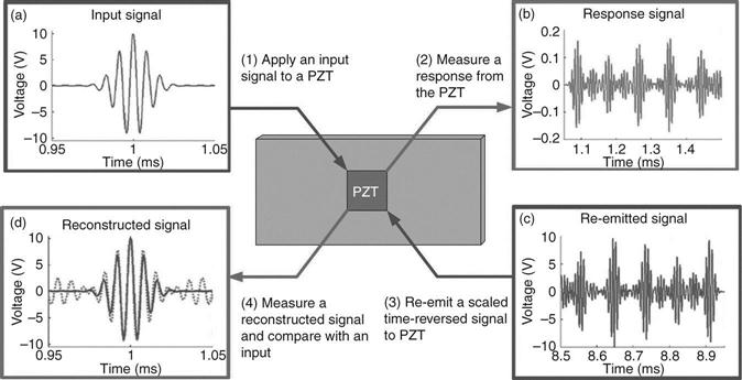
Figure 4.16 shows an overview of the TRP-based PZT debonding detection procedure. First, a symmetric toneburst input signal is applied to a PZT, and the response reflected off from the boundaries is measured at the same PZT. Then, the measured response is scaled and reversed in the time domain, and re-emitted to the PZT. Finally, the corresponding response, which is named as the reconstructed signal, is measured again at the same PZT. According to TRP, it can be shown that the shape of the reconstructed signal’s main peak should be identical to that of the original input signal, and also symmetric as long as there is no PZT debonding. However, this symmetry breaks down when PZT debonding occurs. For PZT crack detection, the mechanical response power (MRP) index defined as the total energy of the response signal normalized by the input signal energy is used. The basic premise of the MRP index is that the energy that the PZT can exert on the structure, and consequently the energy of the corresponding response, is a function of the driving frequency at a given PZT size. Therefore, the relationship between the MRP index and the driving frequency is altered when the PZT size changes. This technique has a merit of robustness against changing temperature and loading conditions, because the signals are obtained only from the current state of the monitored PZT without relying on baseline signals.
4.8 Applications of piezoelectric transducer-based SHM
Piezoelectric transducers have been mostly used for local damage detection, and there is increasing interest in integrating these local nondestructive testing (NDT) techniques with global vibration monitoring techniques for improved SHM of civil, mechanical, and aerospace systems. In this section, state-of-the-art examples of piezoelectric transducer applications to SHM are presented.
4.8.1 Bridge structures
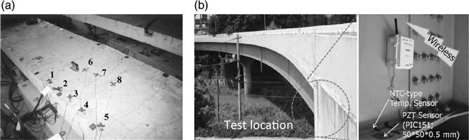
The demands for bridge monitoring are triggered by past historical bridge incidents (Lichtenstein, 1993; Cho et al., 2001; Hao, 2010). To meet these demands, global bridge monitoring techniques have been widely investigated. However, the global monitoring techniques are often insensitive to local incipient damage. To overcome this limitation, local bridge monitoring techniques using piezoelectric transducers have been studied. Soh et al. (2000) carried out crack monitoring of a scaled-prototype RC bridge using electromechanical impedance signals obtained from the embedded PZTs, as shown in Fig. 4.17a. Popovics et al. (2000) investigated surface-breaking cracks in a concrete structure using surface waves generated and measured from surface-mounted PZTs. Park et al. (2006c) investigated the applicability of the guided wave and impedance techniques using PZTs to steel bridge components. More recently, Min et al. (2010b) investigated the applicability of the impedance technique to detection of bolt loosening at a real steel box bridge site using wireless impedance sensor nodes as shown in Fig. 4.17b. In addition, An et al. (2013) investigated the applicability of the reference-free techniques to two in situ bridge sites under varying temperature, and static and dynamic traffic loading conditions.
The piezoelectric transducer-based bridge monitoring, however, still has a number of challenges to be overcome. First, the durability issue of piezoelectric transducer itself is critical. In general, piezoelectric transducers embedded for local bridge monitoring may deteriorate faster than the target bridge structure. To improve their durability, An et al. (2013) examined the ruggedness of packaged PZTs over two years at in situ bridge sites. Second, the wiring often becomes the weakest link in the monitoring system, and electric cabling can be labor-intensive and time consuming. To overcome these limitations, there are several approaches to integrating a wireless telemetry system with PZTs (Lynch and Loh, 2006; Park et al., 2010; Zhou et al., 2010). However, the full validation of this emerging technique for in situ bridge site monitoring is still warranted. Third, advanced signal processing techniques are needed. Since the responses obtained from piezoelectric transducers are sensitive to environmental conditions, such as temperature and loading variations, the development of novel signal processing techniques is necessary to be able to distinguish damage effects from environmental effects. Finally, a new type of piezoelectric transducer needs to be developed that can be placed near critical regions with highstress and high-strain concentrations. Conventional piezoelectric transducers can be impaired or their responses can be saturated when they are subjected to excessive strain.
4.8.2 Aerospace structures
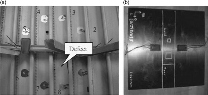
Piezoelectric transducer-based local SHM techniques are also actively studied by the aerospace community because incipient damage in an aircraft structure can lead to a catastrophic disaster. In particular, a large volume of SHM studies, which utilize guided wave and impedance measurements, have been reported, because many aircraft components are fundamentally thin plate-like structures. Chaudhry et al. (1995) investigated the applicability of the impedance technique to local damage detection in a full-scale aircraft using PZTs. Giurgiutiu et al. (2002) utilized PZT-based impedance and guided techniques for monitoring of fatigue cracks and corrosions in an aging aircraft. Zhao et al. (2007) conducted experiments on a full-scale aircraft wing for damage identification and localization using a PZT sensor array as shown in Fig. 4.18a. Di Scalea et al. (2007) studied the monitoring of the composite wing skin-to-spar joint in an unmanned aerial vehicle using guided waves obtained from a pair of MFCs, as shown in Fig. 4.18b. More recently, An et al. (2012) investigated the feasibility of the integrated impedance and guided wave (IIG) technique for monitoring a full-scale aircraft wing structure under temperature and external loading variations. The unique characteristics of piezoelectric transducer SHM of aerospace systems are that (1) piezoelectric transducers should often be embedded inside aircraft, (2) the embedded piezoelectric transducer network should be designed with redundancy because the embedded transducers cannot be easily replaced or repaired, (3) weight of the transducers, wires, onboard data acquisition devices should be minimized, and (4) SHM systems should be designed with caution to avoid interference with existing onboard communications.
4.8.3 Pipeline structures
Piezoelectric transducers have been also used for pipeline monitoring. Lowe et al. (1998) estimated the defect size using a piezoelectric transducer-based guided wave technique in a pipeline structure. Harley et al. (2009) utilized a piezoelectric transducer array for TRP-based pipeline monitoring. Davies and Cawley (2009) developed a guided wave imaging technique for pipeline monitoring using circumferential array of piezoelectric shear transducers, and the effectiveness of the proposed method was numerically and experimentally validated. The uniqueness of pipeline SHM applications is that (1) the conformability of piezoelectric transducers is important, (2) guided waves can travel relatively longer distances than other applications since the energy is confined within the pipe, and (3) often a long range data and power transmission is necessary.
4.8.4 Nuclear power plants
Nuclear energy is seen as one of the most promising alternative energy sources to oil, and monitoring of nuclear power plants (NPPs) is another area where piezoelectric transducers can be potentially exploited. In response to this interest, there have been several preliminary studies where the applicability of piezoelectric transducers to NPP monitoring has been investigated. Stepinski et al. (1998) developed a sensor array made of piezoelectric composites for assessing the structural integrity of nuclear waste fuel. Machado et al. (2000) developed a specially designed PVDF sensor for the monitoring of nuclear fuel assemblies, and their sensors have been tested using a prototype of fuel assembly. More recently, Ai et al. (2010) used piezoelectric AE sensors to detect fatigue cracks in a main cooling pipe system. The biggest challenge for NNP applications is that sensors often need to be embedded for online monitoring, and should be designed to withstand high temperature and radiation. To the best knowledge of the authors, currently there are no commercially available piezoelectric transducers that can meet these stringent requirements imposed by NNPs.
4.8.5 Wind turbines
The monitoring of wind turbine structures has just begun to germinate, in response to the recent energy crisis and demands of clean energy (Schulz and Sundaresan, 2006). Sundaresan et al. (2002) utilized a PZT-based guided wave technique to investigate excessive load-induced damage in a wind turbine blade under static loading conditions. Joosse et al. (2002) also monitored a rotor blade to identify and localize damage from a series of static and fatigue tests using an AE technique. Pitchford et al. (2007) validated the applicability of the PZT- and MFC-based impedance techniques for wind blade monitoring through actual blade testing. For online wind blade monitoring, it is imperative to embed sensors inside wind blades so that they do not interfere with the aerodynamic characteristics of blades. Furthermore, the power and data transmission between the blades and the base monitoring station becomes a daunting test. On the other hand, the repeated global vibration caused by the rotating blades offers an opportunity for combined global and local techniques, such as a vibro-acoustic technique where high-frequency ultrasonic signals generated by an embedded piezoelectric transducer are modulated by the global low-frequency excitation generated by the rotating blades when certain types of damage appear (Duffour et al., 2006).
4.8.6 Other fields
Piezoelectric transducers have been widely utilized in the fields of high-precision and vibration controls. For high-precision control applications, Kim et al. (2005b) developed a micro-tensile testing machine using PZT actuators. Fleming and Leang (2010) developed a nano-positioning platform using piezoelectric transducers, as shown in Fig. 4.19a. Examples of commercial applications to high-precision controls are available at Physik Instrumente Inc. (http://www.physikinstrumente.com/). As for vibration control, Vautier and Meheimani (2005) used PZT patches to reduce undesirable vibration in an aluminum beam, as shown in Fig. 4.19b.

Another growing area of application is energy harvesting. To name a few, Choi et al. (2005) developed a thin-film PZT-based energy harvesting micro-electromechanical systems (MEMS) device for long-term SHM applications. Ericka et al. (2005) modeled an energy harvesting generator using piezoelectric membranes. Wang and Xu (2007) invented an energy harvesting device based on air-spaced piezoelectric cantilevers. Traditionally, energy harvesting using piezoelectric transducers has been limited to a relatively high-frequency range (kHz), but recently there have been several studies where energy was harnessed using piezoelectric transducers from low-frequency vibrations (Priya, 2007).
4.9 Future trends
As shown in the previous section, the application of piezoelectric transducers to the SHM field is increasing. However, there are still many challenging technical hurdles that have to be overcome before piezoelectric transducers can be widely accepted for SHM applications. In this section, new research trends, and novel ongoing efforts that might be able to address some of the current technical difficulties, are briefly introduced.
4.9.1 High-temperature piezoelectric transducers
High-temperature piezoelectric transducers have great potential application, such as NPP monitoring. However, the piezoelectricity of typical piezoelectric transducers deteriorates as temperature increases. To overcome this limitation, researchers have investigated alternative piezoelectric materials that retain their piezoelectricity even at high temperature. Materials such as lithium niobate (LiNbO3), ferroelectric crystals (Sr2Nb2O7 and La2Ti2O7), and aluminum nitride films have turned out to have great thermal stability and resistivity (Turner et al., 1994). For example, Kobayashi et al. (2010) developed an ultrasonic transducer operating up to 500 °C using the same material and successfully tested up to 500 °C. However, the manufacturing cost of these compounds is high, due to their high melting points.
4.9.2 High-strain piezoelectric transducers
Piezoelectric transducers often need to be placed near structurally critical areas where expected stress and strain levels are high. However, typical piezoelectric transducers become less responsive when they are subjected to high strain. For this reason, the development of high-strain piezoelectric transducers is necessary for SHM applications. For actuation, high-strain piezoelectric transducers that can endure high-temperature environments have been developed (Donnelly et al., 2007; Kurihara and Masao, 2008). However, the performance of these high-strain piezoelectric transducers for sensing is still questionable. Therefore, the development of high-strain piezoelectric transducers not only for actuation but also for sensing is a future requirement for building a robust SHM system.
4.9.3 Integration with optic-based SHM techniques
Recently, a number of optic-based SHM techniques using piezoelectric transducers have been reported. First, an optic-based wireless PZT excitation and sensing system using laser and optoelectronic devices was proposed by Park et al. (2010). In this system, the input waveform for PZT excitation as well as the power required for wireless sensing is remotely transmitted via a continuous laser source. Second, optic-based hybrid systems combining piezoelectric transducers for guided wave generation and fiber-optic for sensing have been proposed (Betz et al., 2003; Takeda et al., 2005). These hybrid systems are less susceptible to noise and capable of multi-point sensing. Third, a combination of piezoelectric transducer and laser for either noncontact sensing or excitation has been proposed and successfully validated by several researchers (Staszewski et al., 2004b; Leong et al., 2005; Sohn et al., 2011b). In these systems, excitation is done by a piezoelectric transducer and sensing is done by noncontact laser, or inversely the excitation can be achieved by laser and sensing by a piezoelectric transducer. The main advantage of these systems is that wavefield visualization with high spatial and temporal resolution can be achieved by laser scanning, making it possible to identify and localize damage without solving a complex inverse problem.
4.9.4 Nano-piezoelectric transducers
There is an increased interest in developing nano-scaled piezoelectric transducers due to the advantages of its ultra-compactness and meticulous precision control. Nano-scaled piezoelectric powders, which are central to the nano-piezoelectric transducers, have been developed for versatile precision control applications (Reddy et al, 2002; Lee et al, 2006; Sinha et al, 2009). These studies have revealed that the nano-scaled piezoelectric transducers have comparable piezoelectric coefficients to bulk piezoelectric transducers, although their elastic modulus is lower than that of the bulk transducers. Then, Chen et al. (2010) developed a new piezoelectric nano-fiber transducer for mechanical energy harvesting. However, applications of nanopiezoelectric transducers to SHM community have not been much focused on. Thus, further study on the utilization of nano-piezoelectric transducers to SHM field is warranted.
4.9.5 Multi-functional piezoelectric sensing
As described in this chapter, piezoelectric transducers are widely used for damage detection techniques based on guided wave, impedance, and AE measurement. Naturally, there is a strong desire to design a single multifunctional piezoelectric transducer that can be used for simultaneous measurements of these different types of signals and corresponding damage detection techniques. The advantage of this multi-functional sensing might be that the number of necessary sensors can be reduced, and information gained from various signal measurements and damage detection algorithms can be synergistically combined for improved SHM diagnosis. The difficulty here is that measurements of guided wave, impedance, and AE signals are based on different principles and require different constraints for transducer designs. Therefore, it becomes difficult to design a single piezoelectric transducer that can meet all these various design requirements. For example, it is typically desirable to increase the transducer size for actuation applications. On the other hand, the smaller transducer achieves higher sensing sensitivity. Song et al. (2008) developed a multi-functional piezoelectric device, i.e., smart aggregates, to use in early-age concrete strength monitoring, impact detection, and health monitoring of concrete structures. For the multifunctional PZT sensing, An and Sohn (2011) proposed an IIG technique to improve the detectability of various types of damages such as cracking, bolt loosening, and delamination.
4.10 Conclusion
In this chapter, the working principles and characteristics of piezoelectric transducers are described first, and then their fabrication process and applications are introduced. In particular, their applications to state-of-the-art SHM are highlighted. The direct and converse piezoelectricity effects of piezoelectric materials allow them to be used both for actuation and sensing applications, setting them apart from most conventional passive sensors. With the excitation at our full disposal, not only can signal-to-noise ratio be improved but also subsequent signal processing, signal interpretation, and system identification become much straightforward. Furthermore, the nonintrusive nature, low cost, light weight, and good repeatability of the piezoelectric transducers make them attractive for SHM applications, where sensors often need to be permanently installed. However, when it comes to permanent installation and embedded sensing, future research should focus on addressing the long-term ruggedness, miniaturization, increased flexibility, and applications under high-temperature, high-strain, and high-radiation environments.