Chapter 4. Entities and Relationships
In this chapter we look at the basis for all database systems: the relationships between elements in the database environment. The formal term for expressing data relationships to a DBMS is a data model. The relational data model, which you will learn about in this book, is just such a formal structure. However, the underlying relationships in a database are independent of the data model and therefore also independent of the DBMS you are using. Before you can design a database for any data model, you need to be able to identify data relationships.
Note: Most DBMSs support only one data model. Therefore, when you choose a DBMS, you are also choosing your data model.
Entities and Their Attributes
An entity is something about which we store data. A customer is an entity, as is a merchandise item stocked by Antique Opticals. Entities are not necessarily tangible. For example, a concert or a doctor's appointment is an entity.
Entities have data that describe them (their attributes). For example, a customer entity is usually described by a customer number, first name, last name, street, city, state, zip code, and phone number. A concert entity might be described by a title, date, location, and name of the performer.
When we represent entities in a database, we actually store only the attributes. Each group of attributes that describes a single real-world occurrence of an entity acts to represent an instance of an entity. For example, in Figure 4-1, you can see four instances of a customer entity stored in a database. If we have 1000 customers in our database, there will be 1000 collections of customer attributes.

Note: Keep in mind that we are not making any statements about how the instances are physically stored. What you see in Figure 4-1 is purely a conceptual representation.
Entity Identifiers
The only purpose for putting the data that describe an entity into a database is to retrieve the data at some later date. This means that we must have some way of distinguishing one entity from another so that we can always be certain that we are retrieving the precise entity we want. We do this by ensuring that each entity has some attribute values that distinguish it from every other entity in the database (an entity identifier).
Assume, for example, that Antique Opticals has only two customers named John Smith. If an employee searches for the items John Smith has ordered, which John Smith will the DBMS retrieve? In this case, the answer is both of them. Because there is no way to distinguish between the two customers, the result of the query will be inaccurate. Antique Opticals solved the problem by creating customer numbers that were unique. That is indeed a common solution to identifying instances of entities where there is no simple unique identifier suggested by the data itself.
Another solution would be to pair the customer's first name and last name with his or her telephone number. This combination of data values (a concatenated identifier) would also uniquely identify each customer. There are, however, two drawbacks to doing so this. First, the identifier is long and clumsy; it would be easy to make mistakes when entering any of the parts. Second, if the customer's phone number changes, then the identifier must also change. As you read in Chapter 3, changes made in an entity identifier can cause serious problems in a database.
Some entities, such as invoices, come with natural identifiers (the invoice number). We assign unique, meaningless numbers to others, especially accounts, people, places and things. Still others require concatenated identifiers.
Note: We will examine the issue of what makes a good unique identifier more closely in Chapter 5 when we discuss “primary keys.”
When we store an instance of an entity in a database, we want the DBMS to ensure that the new instance has a unique identifier. This is an example of a constraint on a database, a rule to which data must adhere. The enforcement of a variety of database constraints helps us to maintain data consistency and accuracy.
Single-Valued versus Multivalued Attributes
Because we are eventually going to create a relational database, the attributes in our data model must be single-valued. This means that for a given instance of an entity, each attribute can have only one value. For example, a customer entity allows only one telephone number for each customer. If a customer has more than one phone number and wants all of them in the database, then the customer entity cannot handle them. The existence of more than one phone number turns the phone number attribute into a multivalued attribute. Because an entity in a relational database cannot have multivalued attributes, you must handle those attributes by creating an entity to hold them.
Note: While it is true that the entity-relationship model of a database is independent of the formal data model used to express the structure of the data to a DBMS, we often make decisions on how to model the data based on the requirement of the formal data model we will be using. Removing multivalued attributes is one such case. You will also see an example of this when we deal with many-to-many relationships between entities.
In the case of the multiple phone numbers, we could create a phone number entity. Each instance of the entity would include the customer number of the person to whom the phone number belonged along with the telephone number. If a customer had three phone numbers, then there would be three instances of the phone number entity for the customer. The entity's identifier would be the concatenation of the customer number and the telephone number.
Note: There is no way to avoid using the telephone number as part of the entity identifier in the telephone number entity. As you will come to understand as you read this book, in this particular case there is no harm in using it in this way.
What is the problem with multivalued attributes? Multivalued attributes can cause problems with the meaning of data in the database, significantly slow down searching, and place unnecessary restrictions on the amount of data that can be stored.
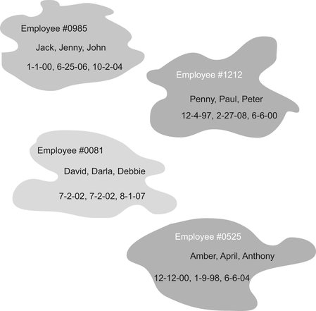
Assume, for example, that you have an employee entity with attributes for the name and birth dates of dependents. Each attribute is allowed to store multiple values, as in Figure 4-2, where each gray blob represents a single instance of the employee entity. How will you associate the correct birth date with the name of the dependent to which it applies? Will it be by the position of a value stored in the attribute (i.e., the first name is related to the first birth date, and so on)? If so, how will you ensure that there is a birth date for each name and a name for each birth date? How will you ensure that the order of the values is never mixed up?
When searching a multivalued attribute, a DBMS must search each value in the attribute, most likely scanning the contents of the attribute sequentially. A sequential search is the slowest type of search available.
In addition, how many values should a multivalued attribute be able to store? If you specify a maximum number, what will happen when you need to store more than the maximum number of values? For example, what if you allow room for 10 dependents in the employee entity just discussed and you encounter an employee with 11 dependents? Do you create another instance of the employee entity for that person? Consider all the problems that doing so would create, particularly in terms of the unnecessary duplicated data.
Note: Although it is theoretically possible to write a DBMS that will store an unlimited number of values in an attribute, the implementation would be difficult and searching much slower than if the maximum number of values were specified in the database design.
As a general rule, if you run across a multivalued attribute, this is a major hint that you need another entity. The only way to handle multiple values of the same attribute is to create an entity in which you can store multiple instances, one for each value of the attribute (for example, Figure 4-3). In the case of the employee entity, we would need a dependent entity that could be related to the employee entity. There would be one instance of the dependent entity related to an instance of the employee entity for each of an employee's dependents. In this way, there is no limit to the number of an employee's dependents. In addition, each instance of the dependent entity would contain the name and birth date of only one dependent, eliminating any confusion about which name was associated with which birth date. Searching would also be faster because the DBMS could use fast searching techniques on the individual dependent entity instances without resorting to the slow sequential search.

Avoiding Collections of Entities
When you first begin to work with entities, you may find the nature of an entity to be somewhat confusing. Consider, for example, the merchandise inventory handled by Antique Opticals. Is “inventory” an entity? No. Inventory is a collection of the merchandise items handled by the store. The entity is actually the merchandise item. Viewing all of the instances of the merchandise item entity as a whole provides the inventory.
To make this a bit clearer, consider the attributes you would need if you decided to include an inventory entity: merchandise item number, item title, number in stock, retail price, and so on. But because you are trying to describe an entire inventory with a single entity, you need multiple values for each of those attributes. As you read earlier, however, attributes cannot be multivalued. This tells you that inventory cannot stand as an entity. It must be represented as a collection of instances of a merchandise item entity.
As another example, consider a person's medical history maintained by a doctor. Like an inventory, a medical history is a collection of more than one entity. A medical history is made up of appointments and the events that occur during those appointments. Therefore, the history is really a collection of instances of appointment entities and medical treatment entities. The “history” is an output that a database application can obtain by gathering the data stored in the underlying instances.
Documenting Entities and Their Attributes
Entity-relationship (ER) diagrams (ERDs) provide a way to document the entities in a database along with the attributes that describe them. There are actually several styles of ER diagrams. Today there are three major methods: the Chen model (named after the originator of ER modeling, Dr. Peter P.S. Chen), Information Engineering (IE, or “crows feet”), and Unified Modeling Language (UML).
If you are not including object-oriented concepts in a data model, it really doesn't matter which you use, as long as everyone who is using the diagram understands the symbols. However, UML is specifically intended for the object-oriented environment and is usually the choice when objects are included.
All three diagramming styles use rectangles to represent entities. Each entity's name appears in the rectangle and is expressed in the singular, as in
The original Chen model has no provision for showing attributes on the ER diagram itself. However, many people have extended the model to include the attributes in ovals:
 |
The entity's identifier is underlined (id_numb).
Note: An alternative to the Chen style of diagramming, which does include the attribute ovals, is the Information Engineering style, which grew out of the work of James Martin and Clive Finkelstein.
The IE and UML styles of ER diagramming include the attributes in the rectangle with the entity:
 |
Entities and Attributes for Antique Opticals
The major entities and their attributes for the Antique Opticals database can be found in Figure 4-4. As you will see, the design will require additional entities as we work with the relationships between those already identified. In particular, there is no information in Figure 4-4 that indicates which items appear on which orders and no information about which used laser discs are purchased by the store during a single transaction. This occurs because the missing information is a part of the logical relationships between customers, orders, purchases, and items.

Note: The entities in Figure 4-4 and the remainder of the diagrams in this book were created with a special type of software known as a computer-aided software engineering (CASE) tool. CASE tools provide a wide range of data and systems modeling assistance. You will find more details on how CASE tools support the database design process in Chapter 11.
Figure 4-4 demonstrates some of the choices made for the Antique Opticals database. Notice, for example, that there is only one entity for merchandise items, yet the store carries new DVDs, new high-definition DVDs, and used laser discs. The item_type attribute distinguishes the three types of merchandise. Because all merchandise items are stored as the same type of entity, queries such as “Show me Star Wars IV in any format” will be easy to perform using just the item name, and queries such as “Do you have a used Star Wars IV laser disc?” will be easy to satisfy using both the title of the item and its type.
Domains
Each attribute has a domain, an expression of the permissible values for that attribute. A domain can be very small. For example, a T-shirt store might have a size attribute for its merchandise items with the values L, XL, and XXL comprising the entire domain. In contrast, an attribute for a customer's first name, being very long might be specified only as “text” or “human names.”
A DBMS enforces a domain through a domain constraint. Whenever a value is stored in the database, the DBMS verifies that it comes from the attribute's specified domain. Although in many cases we cannot specify small domains, at the very least the domain assures us that we are getting data of the right type. For example, a DBMS can prevent a user from storing 123 × 50 in an attribute whose domain is currency values. Most DBMSs also provide fairly tight domain checking on date and time attributes, which can help you avoid illegal dates such as February 30.
Documenting Domains
The common formats used for ER diagrams do not usually include domains on the diagrams themselves but store the domains in an associated document (usually a data dictionary, something you will learn more about later in this book). However, the version of the Chen method that includes attributes can also include domains underneath each attribute. Notice in Figure 4-5 that three of the domains are fairly general (integer and character), while the domain for the telephone number attribute includes a very specific format. Whether a domain can be constrained in this way depends on the DBMS.

Note: There is no specific syntax for indicating domains. However, if you know which DBMS you will be using, consider using the column data types supported by that product as domains in an ERD to simplify the later conversion to the DBMS's representation.
Practical Domain Choices
The domains that Antique Opticals chooses for its attributes should theoretically be independent of the DBMS that the company will use. In practical terms, however, it makes little sense to assign domains that you cannot implement. Therefore, the database designer working for Antique Opticals takes a look at the DBMS to see what data types are supported.
Most relational DBMSs that use SQL as their query language provide the following among their data types, any of which can be assigned as a domain to an attribute:
▪ CHAR: A fixed-length string of text, usually up to 256 characters
▪ INT: An integer, the size of which varies depending on the operating system
▪ DECIMAL and NUMERIC: Real numbers, with fractional portions assigned to the right of the decimal point. When you assign a real number domain, you must specify how many digits the number can contain (including the decimal point) and how many digits should be to the right of the decimal point (the value's precision). For example, currency values usually have a precision of two, so a number in the format XXX.XX might have a domain of DECIMAL (6,2).
▪ DATE: A date
▪ TIME: A time
▪ DATETIME: The combination of a date and a time
▪ BOOLEAN: A logical value (true or false)
Many current DBMSs also support a data type known as a BLOB (binary large object), which can store anything binary, such as a graphic.
Choosing the right domain can make a big difference in the accuracy of a database. For example, a U.S. zip code is made up of five or nine digits. Should an attribute for a zip code therefore be given a domain of INT? The answer is no, for two reasons. First, it would be nice to be able to include the hyphen in nine-digit zip codes. Second, and more important, zip codes in the Northeast begin with a zero. If they are stored as a number, the leading zero disappears. Therefore, we always choose a CHAR domain for zip codes. Since we never do arithmetic with zip codes, nothing is lost by using character rather than numeric storage.
By the same token, it is important to choose domains of DATE and TIME for chronological data. As an example, consider what would happen if the dates 01/12/2009 and 08/12/2008 were stored as characters. If you ask the DBMS to choose which date comes first, the DBMS will compare the character strings in alphabetical order and indicate that 01/12/2009 comes first, because 01 alphabetically precedes 08. The only way to get character dates to order correctly is to use the format YYYY/MM/DD, a format that is rarely used anywhere in the world. However, if the dates were given a domain of DATE, then the DBMS would order them properly. The DBMS would also be able to perform date arithmetic, finding the interval between two dates or adding constants (for example, 30 days) to dates.
Basic Data Relationships
Once you have a good idea of the basic entities in your database environment, your next task is to identify the relationships among those entities. There are three basic types of relationships that you may encounter: one-to-one (1 : 1), one-to-many (1 : M), and many-to-many (M : N or M : M).
Before examining each type, you should keep one thing in mind: The relationships that are stored in a database are between instances of entities. For example, an Antique Opticals customer is related to the items that he or she orders. Each instance of the customer entity is related to instances of the specific items ordered (see Figure 4-6).

When we document data relationships, such as when we draw an ER diagram, we show the types of relationships among entities. We are showing the possible relationships that are allowable in the database. Unless we specify that a relationship is mandatory, there is no requirement that every instance of every entity must be involved in every documented relationship. For example, Antique Opticals could store data about a customer without the customer having any orders to which it is related.
One-to-One Relationships
Consider, for a moment, an airport in a small town, where both the airport and the town are described in a database of small-town airports. Each of these might be represented by an instance of a different type of entity. The relationship between the two instances can be expressed as “The airport is located in one and only one town, and the town has one and only one airport.”
This is a true one-to-one relationship because at no time can a single airport be related to more than one town, and no town can be related to more than one airport. (Although there are municipalities that have more than one airport, the towns in the database are too small for that to ever happen.)
If we have instances of two entities (A and B) called Ai and Bi, then a one-to-one relationship exists if at all times Ai is related to no instances of entity B or one instance of entity B, and Bi is related to no instances of entity A or one instance of entity A.
True one-to-one relationships are very rare in business. For example, assume that Antique Opticals decides to start dealing with a new distributor of DVDs. At first, the company orders only one specialty title from the new distributor. If we peered inside the database, we would see that the instance of the distributor entity was related to just the one merchandise item instance. This would then appear to be a one-to-one relationship. However, over time, Antique Opticals may choose to order more titles from the new distributor, which would violate the rule that the distributor must be related to no more than one merchandise item. (This is an example of a one-to-many relationship, which is discussed in the next section of this chapter.)
By the same token, what if Antique Opticals created a special credit card entity to hold data about the credit cards that customers use to place orders? Each order can be charged to only one credit card. Thus, there would seem to be a one-to-one relationship between an instance of an order entity and an instance of a credit card entity. However, in this case we are really dealing with a single entity. The credit card number and the credit card's expiration date can become attributes of the order entity. Given that only one credit card is allowed per order, the attributes are not multivalued, and no separate entity is needed.
If you think you are dealing with a one-to-one relationship, look at it very carefully. Be sure that you are not really dealing with a special case of a one-to-many relationship or two entities that should really be one.
One-to-Many Relationships
The most common type of relationship is a one-to-many relationship. (In fact, most relational databases are constructed from the rare one-to-one relationship and numerous one-to-many relationships.) For example, Antique Opticals typically orders many titles from each distributor, and a given title comes from only one distributor. By the same token, a customer places many orders, but an order comes from only one customer. If we have instances of two entities (A and B), then a one-to-many relationship exists between two instances (Ai and Bi) if Ai is related to zero, one, or more instances of entity B and Bi is related to zero or one instance of entity A.
Other one-to-many relationships include that between a daughter and her biological mother. A woman may have zero, one, or more biological daughters; a daughter can have only one biological mother. As another example, consider a computer and its CPU. A CPU may not be installed in any computer, or it may be installed in at most one computer. A computer may have no CPU, one CPU, or more than one CPU.
Our previous example of Antique Opticals and the distributor from which it ordered only one title is actually a one-to-many relationship where the “many” is currently “one.” Remember that when we are specifying data relationships, we are indicating possible relationships and not necessarily requiring that all instances of all entities participate in every documented relationship. There is absolutely no requirement that a distributor be related to any merchandise item, much less one or more merchandise items. (It might not make much sense to have a distributor in the database from which the company does not order, but there is nothing to prevent data about that distributor from being stored.)
Many-to-Many Relationships
Many-to-many relationships are also very common. There is, for example, a many-to-many relationship between an order placed by an Antique Opticals customer and the merchandise items carried by the store. An order can contain multiple items, and each item can appear on more than one order. The same is true of the orders placed with distributors. An order can contain multiple items and each item can appear on more than one order.
A many-to-many relationship exists between entities A and B if for two instances of those entities (Ai and Bi) Ai can be related to zero, one, or more instances of entity B and Bi can be related to zero, one, or more instances of entity A.
Many-to-many relationships present two major problems to a database's design. These issues and the way in which we solve them are discussed later in the next major section, of this chapter (“Dealing with Many-to-Many Relationships”).
Weak Entities and Mandatory Relationships
In our discussion of types of data relationships, we have defined those relationships by starting each with “zero,” indicating that the participation by a given instance of an entity in a relationship is optional. For example, Antique Opticals can store data about a customer in its database before the customer places an order. Therefore, an instance of the customer entity does not have to be related to any instances of the order entity.
However, the reverse is not true in this database. An order must be related to a customer. Without a customer, an order cannot exist. An order is therefore an example of a weak entity, one that cannot exist in the database unless a related instance of another entity is present and related to it. An instance of the customer entity can be related to zero, one, or more orders. However, an instance of the order entity must be related to one and only one customer. The “zero” option is not available to a weak entity. The relationship between an instance of the order entity and an instance of the customer entity is therefore a mandatory relationship.
Identifying weak entities and their associated mandatory relationships can be very important for maintaining the consistency and integrity of the database. Consider the effect, for example, of storing an order without knowing the customer to which it belongs. There would be no way to ship the item to the customer, and the company would lose business.
By the same token, we typically specify the relationship between an order and the order lines (the specific items on the order) as mandatory because we don't want to allow an order line to exist in the database without it being related to an order. (An order line is meaningless without knowing the order to which it belongs.)
In contrast, we can allow a merchandise item to exist in a database without indicating the supplier from which is comes (assuming that there is only one source per item). This lets us store data about new items before we have decided on a supplier. In this case, the relationship between a supplier and an item is not mandatory (often described as zero-to-many rather than one-to-many).
Documenting Relationships
The Chen and UML methods of drawing ER diagrams have very different ways of representing relationships, each of which has its advantages in terms of the amount of information it provides and its complexity.
The Chen Method
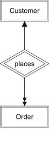
The Chen method uses diamonds for relationships and lines with arrows to indicate the relationships between entities. For example, in Figure 4-7 you can see the relationship between an Antique Opticals customer and an order. The single arrow pointing toward the customer entity indicates that an order belongs to at most one customer. The double arrow pointing toward the order entity indicates that a customer can place one or more orders. The word within the relationship diamond gives some indication of the meaning of the relationship.
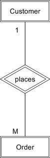
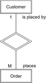
There are two alternative styles within the Chen method. The first replaces the arrows with numbers and letters (see Figure 4-8). A “1” indicates that an order comes from one customer. The “M” (or an “N”) indicates that a customer can place many orders. The second alternative addresses the problem of trying to read the relationship in both directions when the name of the relationship is within the diamond. “Customer places order” makes sense, but “order places customer” does not. To solve the problem, this alternative removes the relationship name from the diamond and adds both the relationship and its inverse to the diagram, as in Figure 4-9. This version of the diagram can be read easily in either direction: “A customer places many orders” and “An order is placed by one customer.”
There is one major limitation to the Chen method of drawing ER diagrams: There is no obvious way to indicate weak entities and mandatory relationships. For example, an order should not exist in the database without a customer. Therefore, order is a weak entity and its relationship with a customer is mandatory.
IE Style Diagrams
The IE diagramming style exchanges simplicity in line ends for added information. As a first example, consider Figure 4-10. This is the same one-to-many relationship we have been using to demonstrate the Chen method ER diagrams. However, in this case, the ends of the lines (which look a little like a bird's foot and are often called “crows feet”) indicate which relationships are mandatory.

The double line below the customer entity means that each order is related to one and only one customer. Because zero is not an option, the relationship is mandatory. In contrast, the 0 and the crow's foot connected to the order entity mean that a customer may have zero, one, or more orders.
There are four symbols used at the ends of lines in an IE diagram:
||: One and one only (mandatory relationship)
0|: Zero or one
>1: One or more (mandatory relationship)
>0: Zero, one, or more
Although we often see the symbols turned 90 degrees, as they are in Figure 4-10, they are actually readable if viewed sideways as in the preceding list. An IE method ER diagram often includes attributes directly on the diagram. As you can see in Figure 4-10, entity identifiers are marked with an asterisk.
UML Style Diagrams
UML notation for entity relationships is very similar to IE notation. However, the symbols at the ends of lines are replaced by numeric representations of the type of relationship (see Figure 4-11). There are four possible relationships:

1: One and only one (mandatory)
1…*: One or more (mandatory)
0…1: Zero or one
0…*: Zero, one, or more
Basic Relationships for Antique Opticals
The major entities in the Antique Opticals database are diagrammed in Figure 4-12. You read the relationships in the following way:
 |
| ▪ Figure 4-12 |
▪ One customer can place zero, one, or more orders. An order comes from one and only one customer.
▪ The store may make many purchases of used discs from one customer. A purchase transaction comes from one and only one customer.
▪ A purchase is made up of one or more items. An item can be purchased zero, one, or more times.
▪ An actor appears in zero, one, or more items. An item has zero, one, or more actors in it. (There may occasionally be films that feature animals rather than human actors; therefore, it is probably unwise to require that every merchandise item be related to at least one actor.)
▪ Each item has zero, one, or more producers. Each producer is responsible for zero, one, or more items. (Although in practice you would not store data about a producer unless that producer was related to an item, leaving the relationship between a producer and an item as optional means that you can store producers without items if necessary.)
▪ Each item comes from zero or one distributor. Each distributor supplies zero, one, or more items.
The major thing to notice about this design is that there are four many-to-many relationships: order to item, purchase to item, actor to item, and producer to item. Before you can map this data model to a relational database, they must be handled in some way.
Dealing with Many-to-Many Relationships
As you read earlier, there are problems with many-to-many relationships. The first is fairly straightforward: The relational data model cannot handle many-to-many relationships directly; it is limited to one-to-one and one-to-many relationships. This means that you must replace the many-to-many relationships that you have identified in your database environment with a collection of one-to-many relationships if you want to be able to use a relational DBMS.
The second, however, is a bit more subtle. To understand it, consider the relationship between an order a customer places with Antique Opticals and the merchandise items on the order. There is a many-to-many relationship between the order and the item because each order can be for many items and each item can appear on many orders (typically orders from different customers). Whenever a customer orders an item, the number of copies of the item varies, depending on how many copies the customer needs. (Yes, typically people order only one copy of a movie, but we need to allow them to order as many as they want.)
Now the question: Where should we store the quantity being ordered? It cannot be part of the order entity because the quantity depends on which item we are talking about. By the same token, the quantity cannot be part of the item entity because the quantity depends on the specific order.
This scenario is known as relationship data—data that apply to the relationship between two entities rather than to the entities themselves. Relationships, however, cannot have attributes. We therefore must have some entity to represent the relationship between the two, an entity to which the relationship data can belong.
Composite Entities
Entities that exist to represent the relationship between two or more other entities are known as composite entities. As an example of how composite entities work, consider once again the relationship between an order placed by an Antique Opticals customer and the items on that order.
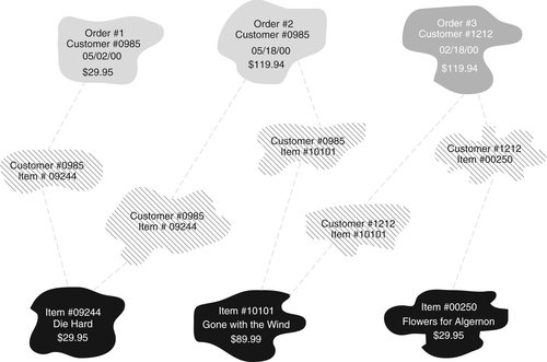
What we need is an entity that tells us that a specific title appears on a specific order. If you look at Figure 4-13, you will see three order instances and three merchandise item instances. The first order for customer 0985 (Order #1) contains only one item (item 09244). The second order for customer 0985 (Order #2) contains a second copy of item 09244 as well as item 10101. Order #3, which belong to customer 1212, also has two items on it (item 10101 and item 00250).
 |
| ▪ Figure 4-13 |
There are five items ordered among the three orders. The middle of the diagram therefore contains five instances of a composite entity we will call a “line item” (think of it as a line item on a packing slip). The line item entity has been created solely to represent the relationship between an order and a merchandise item.
Each order is related to one line item instance for each item in the order. In turn, each item is related to one line item instance for each order on which it appears. Each line item instance is related to one and only one order, and it is also related to one and only one merchandise item. As a result, the relationship between an order and its line items is one-to-many (one order has many line items), and the relationship between an item and the orders on which it appears is one-to-many (one merchandise item appears in many line items). The presence of the composite entity has removed the original many-to-many relationship.
If necessary, the composite entity can be used to store relationship data. In the preceding example, we might include an attribute for the quantity ordered, a flag to indicate whether it has been shipped, and a shipping date.
Documenting Composite Entities
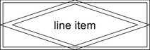
In some extensions of the Chen method for drawing ER diagrams, the symbol for a composite entity is the combination of the rectangle used for an entity and the diamond used for a relationship:
 |
Resolving Antique Opticals' Many-to-Many Relationships
To eliminate Antique Opticals' many-to-many relationships, the database designer must replace each many-to-many relationship with a composite entity and two one-to-many relationships. As you can see in Figure 4-14, the four new entities are as follows:

▪ Order item: An instance of the order item entity represents one item appearing on one order. Each order can have many “order items,” but an ordered item must appear on one and only one order. By the same token, an ordered item contains one and only one item, but the same item can appear in many order item instances, each of which is related to a different order.
▪ Purchase item: An instance of the purchase item entity represents one used laser disc purchased from one customer as part of a purchase of one or more discs. Many items can be purchased during a single transaction, but each item purchased is purchased during only one transaction. The purpose of the purchase item entity is therefore the same as the order item entity: to represent specific items in a single transaction.
▪ Performance: The performance entity represents one actor appearing in one film. Each performance is for one and only one film, although a film can have many performances (one for each actor in the film). Conversely, an actor is related to one performance for each film in which he or she appears, although each performance is in one and only one film.
▪ Production: The production entity represents one producer working on one film. A producer may be involved in many productions, although each production relates to one and only one producer. The relationship with the item indicates that each film can be produced by many producers but that each production relates to only one item.
Note: If you find sorting out the relationships in Figure 4-14 a bit difficult, keep in mind that if you rotate the up-and-down symbols 90 degrees, you will actually be able to read the relationships.
Because composite entities exist primarily to indicate a relationship between two other entities, they must be related to both of their parent entities. This is why the relationship between each composite entity in Figure 4-14 and its parents is mandatory.
Relationships and Business Rules
In many ways, database design is as much an art as a science. Exactly what is the “correct” design for a specific business depends on the business rules; what is correct for one organization may not be correct for another. For example, assume that you are creating a database for a small establishment that has more than one store. One of the things you are being asked to model in the database is an employee's schedule. Before you can do that, you need to determine the relationship between an employee and a store. Is it one-to-many or many-to-many? Does an employee always work in one store—in which case the relationship is one-to-many—or can an employee divide his or her time among stores, which would mean a many-to-many relationship? This is not a matter of a correct or incorrect database design but an issue of how the business operates.
Data Modeling versus Data Flow
One of the most common mistakes people make when they begin data modeling is confusing data models with data flows. A data flow shows how data are handled within an organization, including who handles the data, where the data are stored, and what is done to the data. In contrast, a data model depicts the internal, logical relationships between the data, without regard to who is handling the data or what is being done with it.
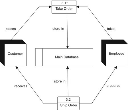
Data flows are often documented in data flow diagrams (DFDs). For example, Figure 4-15 shows a top-level data flow diagram for Antique Opticals. The squares with drop shadows represent the people who are handling the data. Simple rectangles with numbers in them represent processes, or things that are done with the data. A place where data are stored (a data store) appears as two parallel lines—in this example containing the words “Main database.” The arrows on the lines show the direction in which data pass from one place to another.
Data flow diagrams are often exploded to show more detail. For example, Figure 4-16 contains an explosion of the “Take order” process from Figure 4-15. You can now see that the process of taking an order involves two major steps: getting customer information and getting item information.
 |
| ▪ Figure 4-16 An explosion of the “Take order” process from Figure 4-15. |
Each of the processes in Figure 4-16 can be exploded even further to show additional detail (see ▪ Figure 4-17 and ▪ Figure 4-18). At this point, the diagrams are almost detailed enough so that an application designer can plan an application program.
 |
| ▪ Figure 4-17 An explosion of the “Get customer information” process from Figure 4-14. |
 |
| ▪ Figure 4-18 An explosion of the “Get items ordered” process from Figure 4-16. |
Where do the database and the ER diagram fit into all of this? The entire ER diagram is buried inside the “Main database.” In fact, most CASE software allows you to link your ER diagram to a database's representation on a data flow diagram. Then, you can simply double-click on the database representation to the ER diagram into view.
There are a few guidelines for keeping data flows and data models separate:
▪ A data flow shows who uses or handles data. A data model does not.
▪ A data flow shows how data are gathered (the people or other sources from which they come). A data model does not.
▪ A data flow shows operations on data (the process through which data are transformed). A data model does not.
▪ A data model shows the attributes that describe data entities. A data flow does not.
The bottom line is this: A data model contains information about the data being stored in the database (entities, attributes, and entity relationships). If data about an entity are not going to be stored in the database, then that entity should not be part of the data model. For example, although the Antique Opticals data flow diagram shows the employee who handles most of the data, no data about employees are going to be stored in the database. Therefore, there is no employee entity in the ER diagram.
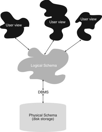
Schemas
A completed entity-relationship diagram represents the overall, logical plan of a database. In database terms, it is therefore known as a schema. This is how the people responsible for maintaining the database will see the design. However, users (both interactive users and application programs) may work with only a portion of the logical schema. And both the logical schema and the users' views of the data are at the same time distinct from the physical storage.
The underlying physical storage, which is managed by the DBMS, is known as the physical schema. It is for the most part determined by the DBMS. (Only very large DBMSs give you any control over physical storage.) The beauty of this arrangement is that both database designers and users do not need to be concerned about physical storage, greatly simplifying access to the database and making it much easier to make changes to both the logical and physical schemas.
Because there are three ways to look at a database, some databases today are said to be based on a three-schema architecture (see Figure 4-19). Systems programmers and other people involved with managing physical storage deal with the physical schema. Most of today's relational DBMSs provide very little control over the file structure used to store database data. However, DBMSs designed to run on mainframes to handle extremely large datasets do allow some tailoring of the layout of internal file storage.
Note: DBMSs based on earlier data models were more closed tied to their physical storage than relational DBMSs. Therefore, systems programmers were able to specify physical file structures to a much greater extent. An overview of the older database models can be found in Appendix A.
Data designers, database administrators, and some application programmers are aware of and use the logical schema. End users who work interactively and application programmers who are creating database applications for them work with the user view of the database.
Throughout most of this book we will focus on the design of the logical schema. You will also learn how to create and use database elements that provide users with limited portions of the database.
The entity-relationship model was developed by Peter P. S. Chen. If you want to learn more about its early forms and how the model has changed, see the following:
Chen, P, The Entity-Relationship Model: Toward a Unified View of Data, ” “ACM Transactions on Database Systems 1 (1) (1976).
Chen, P, Entity-Relationship Approach to Information Modeling. (1981) E-R Institute.
The original work that described the Information Engineering approach can be found in the following:
Finkelstein, Clive, An Introduction to Information Engineering. (1989) Addison-Wesley.
Martin, James, Information Engineering, Book I: Introduction; Book II: Planning and Analysis; Book III: Design and Construction. (1989) Prentice Hall.
For information on the Unified Modeling Language, see the following:
Chonoles, Michael Jessie; Schardt, James A., UML 2 for Dummies. (2003) For Dummies Press.
Fowler, Martin, UML Distilled: A Brief Guide to the Standard Object Modeling Language. 3rd ed (2003) Addison-Wesley Professional.
Pilone, Dan; Pitman, Neil, UML 2.0 in a Nutshell. 2nd ed (2005) O'Reilly Media.
For more in-depth coverage of ER modeling, see any of the following:
Baqui, Skiha; Earp, Richard, Database Design Using Entity-Relationship Diagrams. (2003) Auerbach.
Batini, Carlo; Ceri, Stefano; Navathe, Shamkant B., Conceptual Database Design: An Entity-Relationship Approach. (1991) Addison-Wesley.
Earp, Richard, Database Design Using Entity-Relationship Diagrams. (2007) Taylor & Frances.
..................Content has been hidden....................
You can't read the all page of ebook, please click here login for view all page.