
Chapter 17. Home Automation
17.0 Introduction
As a low-cost and low-power device, a Raspberry Pi makes a great home automation hub that you can leave running without fear of huge electricity bills. For the recipes described in this chapter, you don’t need the power of a Raspberry Pi 4. In fact, a Raspberry Pi 2 or 3 will be plenty fast enough and will run cooler and use less electricity than a Raspberry Pi 4.
We start with Message Queuing Telemetry Transport (MQTT), the basic communication mechanism for most home automation systems, and then move on to look at using Node-RED (which you first met in Chapter 16) as a basis for home automation.
Strictly speaking, home automation is all about making your home smarter and more able to do things for itself—for example, to turn on a light for a set amount of time when movement is detected, or to automatically turn everything off at bedtime. But most people who are interested in home automation are also interested in remote control of the parts of their home that have been automated. We also look at remote control by smartphone in this chapter.
17.1 Making a Raspberry Pi into a Message Broker with Mosquitto
Solution
Install the Mosquitto software so that your Raspberry Pi can act as an MQTT broker.
Run the following commands to install Mosquitto and start it as a service so that it automatically starts when your Raspberry Pi reboots:
$ sudo apt-get update
$ sudo apt install -y mosquitto mosquitto-clients
$ sudo systemctl enable mosquitto.service
You can check to see whether everything is working by running the following command:
$ mosquitto -v
1562320464: mosquitto version 1.4.10 (build date Wed, 13 Feb 2019 00:45:38 +0000)
            starting
1562320464: Using default config.
1562320464: Opening ipv4 listen socket on port 1883.
1562320464: Error: Address already in use
$
The Error message is not really an error; it just means that Mosquitto is already running because we started it as a service.
Discussion
MQTT is a way of passing messages between one program and another. It has two parts:
- Server
- The central place where the passing of messages is controlled and messages are routed to the right recipient.
- Client
- A program that sends and receives messages to and from the server. There will normally be more than one client in a system.
Messages are passed using what is called a publish and subscribe model. That is, a client that has something interesting to say (e.g., a sensor reading) tells the server by publishing the temperature reading. Every few seconds, the client might take another reading and publish that, too.
Messages have a topic and a payload. In a system for automating lights, the topic might be bedroom_light and the payload on or off.
You can try this out by opening two Terminals at the same time. One Terminal will act as the publisher and the other as a subscriber. You can see this in action in Figure 17-1.

Figure 17-1. Two clients communicating using MQTT
Let’s break this down. The Terminal on the left is the subscriber, and here we issue the command:
$ mosquitto_sub -d -t pi_mqtt
Client mosqsub/2007-raspberryp sending CONNECT
Client mosqsub/2007-raspberryp received CONNACK
Client mosqsub/2007-raspberryp sending SUBSCRIBE (Mid: 1, Topic: pi_mqtt, QoS: 0)
Client mosqsub/2007-raspberryp received SUBACK
Subscribed (mid: 1): 0
The mosquitto_sub command subscribes the client. The -d option specifies debug mode, which just means you will see a lot more output about what the client and server are doing; this is useful while you are making sure everything is working. The -t pi_mqtt specifies a topic that the client is interested in as pi_mqtt.
The debug trace shows that the client is connecting to the server without problems and that the client has requested to subscribe and the server has acknowledged the subscription.
Leave this Terminal session running and open a second Terminal session to act as a client that’s going to publish something on the topic pi_mqtt. Enter the following command in this new Terminal window:
$ mosquitto_pub -d -t pi_mqtt -m "publishing hello"
Client mosqpub/2199-raspberryp sending CONNECT
Client mosqpub/2199-raspberryp received CONNACK
Client mosqpub/2199-raspberryp sending PUBLISH (d0, q0, r0, m1, 'pi_mqtt',
                                                ... (16 bytes))
Client mosqpub/2199-raspberryp sending DISCONNECT
Again, the -d and -t options specify debug mode and the topic, but this time there is an extra option of -m, which specifies a message to include in the publication. So if the publisher were a sensor, the message might be the sensor reading.
As soon as the mosquitto_pub command is sent, text like the following will appear in the first Terminal window (the subscriber):
Client mosqsub/5170-raspberryp received PUBLISH (d0, q0, r0, m0, 'pi_mqtt',
	... (16 bytes))
publishing hello
See Also
For information on Mosquitto, see https://mosquitto.org.
For other MQTT recipes in this chapter, see Recipe 17.2 and Recipe 17.5.
17.2 Using Node-RED with an MQTT Server
Solution
Use a Node-RED “mqtt” node and an “rpi gpio” node in a Node-RED flow like the one shown in Figure 17-2.
After you deploy this, you will be able to turn GPIO 18 on and off by sending mosquitto_pub commands. For testing purposes, attach an LED or Raspberry Squid LED to pin 18 (Recipe 10.1).
The flow refers to kitchen lights, as this example pretends that GPIO 18 is being used with something like a PowerSwitch Tail (Recipe 10.6) to switch lighting on and off.
Let’s build the example up one node at a time.

Figure 17-2. A Node-RED MQTT and GPIO workflow
Start by adding an “mqtt” node from the “input” category of Node-RED. Double-click the node to edit it (Figure 17-3).

Figure 17-3. Editing the “mqtt” node
Notice that the Server field just has the option to “Add new mqtt-broker.” We will return to this in a moment. For now, specify a topic (kitchen_lights) and give the node a meaningful name. The QoS field allows you to set the quality of service and determines how persistent the MQTT server is at getting messages to their intended destination. Level 2 means guaranteed delivery.
We now need to define an MQTT server for Node-Red, so click the Edit button next to the Server field. This opens the window shown in Figure 17-4.

Figure 17-4. Adding an MQTT server to Node-RED
Give the server a name and enter “localhost” in the Server field. We can do this because Node-RED and the MQTT server are running on the same Raspberry Pi.
Now we can add the “rpi-gpio out” node. You will find this in the Raspberry Pi section. After you have added it to the flow, open it (Figure 17-5).

Select “12 - GPIO 18” and give the node a name before clicking Done. Drag the connector from the “mqtt in” node to the Raspberry Pi GPIO node so that the flow looks like Figure 17-2.
Click the Deploy button and then open a Terminal session on the Raspberry Pi to test the flow.
Figure 17-5. Editing the GPIO output node
Type the following command in the Terminal window to publish a request to turn on the light:
$ mosquitto_pub -d -t kitchen_lights -m 1
The LED on pin 18 should light. Then, to turn off the LED, send:
$ mosquitto_pub -d -t kitchen_lights -m 0
Discussion
This recipe works only if the Raspberry Pi happens to be right next to the thing you want to control. In reality, you are more likely to want to use a wireless switch.
It is, however, useful to know how to control GPIO pins through MQTT and Node-RED.
Node-RED has the ability to import and export flows as JSON text. All the flows used in this chapter are available on the book’s GitHub pages at https://oreil.ly/WWdcW.
To import one of these flows into Node-RED, visit the GitHub page and then click the recipe number corresponding to the flow that you want to import. For example, in Figure 17-6, I have clicked recipe_17_10.json.

Figure 17-6. Selecting the JSON for a flow from GitHub
Select the whole of the line in the code area and copy it to your clipboard. Then switch back to your Node-RED web page and select the Import → Clipboard option from the Node-RED menu, as shown in Figure 17-7.
Note that when copying the code from GitHub, clicking the Raw button just above the code can make it easier to select all of the code for copying.
Then paste the code you copied from GitHub into the window shown in Figure 17-8 and select “new flow.”

Figure 17-7. Selecting the “Import from Clipboard” option

Figure 17-8. Pasting the flow code into the “Import nodes” dialog box
When you click Import, the flow appears in a new tab (Figure 17-9).

Figure 17-9. A newly imported flow
See Also
To see how you can control a WiFi switch using MQTT, see Recipe 17.5. To see a similar recipe that uses Node-RED instead, see Recipe 17.6.
Read more about MQTT QoS levels.
For more information see the full documentation on Node-RED.
17.3 Flashing a Sonoff WiFi Smart Switch for MQTT Use
Solution
Flash new firmware (Tasmota) onto a low-cost Sonoff WiFi switch, configure the switch through a web interface, and then control it using MQTT.
The Sonoff web switches (shown in Figure 17-10) offer an extremely low-cost way of turning lighting and other appliances on and off wirelessly.

Figure 17-10. The Sonoff WiFi switch
However, the firmware preinstalled on the Sonoff switches is proprietary and relies on servers in China for communication to the internet. If you would prefer to have local control of your device and actually improve over the original firmware, you should follow this recipe to flash new open source firmware onto your Sonoff.
You can do all of this from your Raspberry Pi, but you will need a few things:
A Sonoff web switch (see “Modules”)
A row of four header pins (see “Miscellaneous”)
Four female-to-female jumper wires (see “Prototyping Equipment and Kits”)
Soldering equipment and solder (see “Prototyping Equipment and Kits”)
You will also need a Raspberry Pi 2 or later because earlier Raspberry Pis are not able to provide enough current at 3.3V to power the Sonoff.
Danger: High Voltage
Switching alternating current (AC) using a Sonoff requires the connection of live wires to the Sonoff’s screw terminals. This is electrician’s work and should be done only by someone qualified to do so.
Flash the Sonoff fresh out of its box, before it is wired into your household electricity. You can configure it without connecting it to an AC supply. The Raspberry Pi will power it.
Before you connect your Sonoff to AC, take it apart because you are going to need to solder a strip of four header pins into the holes supplied on the Sonoff’s circuit board. Figure 17-11 shows the position of the holes and also marks off the roles of the four header pins we are interested in. In fact, they are a Serial interface to the Sonoff.

Figure 17-11. Inside a Sonoff WiFi switch
Note that there are four pins and five holes on the Sonoff PCB (printed circuit board), so make sure that you attach header pins to the correct holes.
When you have soldered the header pins into place, the Sonoff should look like Figure 17-12.

Figure 17-12. The Sonoff with header pins attached
You now need to connect the header pins on the Sonoff to the GPIO pins on your Raspberry Pi as follows (use Figure 17-11 as a reference). Because this might cause unexpected resets of your Raspberry Pi, make these connections with your Raspberry Pi powered off.
Sonoff 3.3V to Raspberry Pi 3.3V
Sonoff RXD to Raspberry Pi TXD
Sonoff TXD to Raspberry Pi RXD
Sonoff GND to Raspberry Pi GND
Figure 17-13 shows a Raspberry Pi connected to the Sonoff.

Figure 17-13. Flashing a Sonoff with a Raspberry Pi 2
Raspberry Pi Reboot
Note that when the Sonoff is powered from the Raspberry Pi in this way, it can cause the Raspberry Pi to reset. This is particularly true when putting the Sonoff into flash mode because this starts the WiFi hardware.
Unexpected restarts can leave your SD card corrupted, so be sure to adhere to the following procedure for putting the Sonoff into flash mode while the Raspberry Pi is powered but shutdown so as to avoid any problems with unexpected resets.
Changing the firmware (flashing) the Sonoff requires a piece of Python software called esptool. To download it onto your Raspberry Pi, run the following command:
$ git clone https://github.com/espressif/esptool.git
$ cd esptool
Having downloaded the software, we also need to get hold of the replacement Tasmota firmware to flash onto the Sonoff. To do this, run the following command from within the esptool directory:
$ wget https://github.com/arendst/Sonoff-Tasmota/releases/download/v6.6.0/sonoff-basic.bin
This will fetch a file called sonoff-basic.bin.
The remainder of the process is as follows:
Shut down your Raspberry Pi using this command:
$ sudo shutdown now
Leave the power connected to your Raspberry Pi. It’s now in standby mode.
Put the Sonoff into flash mode.
At the moment, the LED on your Sonoff will probably be happily flashing away. Ironically, when we put it into flash mode, the LED will stop flashing and be unlit. To put the Sonoff into flash mode, you must press the Sonoff’s push switch (Figure 17-11) as the Sonoff is powered up and then release it after a few seconds.
To do this, unplug the 3.3V female-to-female jumper wire at one end (I found the Raspberry Pi end easier to unplug) and then press and hold down the Sonoff’s push switch. Next, reattach the jumper wire and then release the switch. The Sonoff’s LED should no longer be blinking. It’s now in flash mode, ready to receive a new program.
Boot your Raspberry Pi.
To get your Raspberry Pi out of shutdown mode, you need to reset it. You can’t do this by cycling the power, because that would take the Sonoff out of flash mode. So instead follow Recipe 12.14. If you don’t want to actually add a reset button to your Raspberry Pi, you can just use a paper clip bent to the right shape to connect the two reset contacts described in Recipe 12.14.
Erase the Sonoff.
After your Raspberry Pi has booted up, change directory to esptools and then run the command to erase the Sonoff. You should see messages in the Terminal like those shown here:
$ cd /home/pi/esptools
$ python3 esptool.py --port /dev/ttyS0 erase_flash
esptool.py v2.7-dev
Serial port /dev/ttyUSB0
Connecting....
Detecting chip type... ESP8266
Chip is ESP8266EX
Features: WiFi
Crystal is 26MHz
MAC: 5c:cf:7f:3b:69:c4
Uploading stub...
Running stub...
Stub running...
Erasing flash (this may take a while)...
Chip erase completed successfully in 3.1s
Hard resetting via RTS pin...
Shut down your Raspberry Pi and again put the Sonoff into flash mode by repeating steps 2 and 3.
Flash the Tasmota software onto the Sonoff.
Change directory to esptools and then run the command to flash the sonoff-basic.bin file that you fetched earlier onto the Sonoff:
$ cd /home/pi/esptools
$ python3 esptool.py --port /dev/ttyS0 write_flash
  -fs 1MB -fm dout 0x0 sonoff-basic.bin
esptool.py v2.7-dev
Serial port /dev/ttyUSB0
Connecting....
Detecting chip type... ESP8266
Chip is ESP8266EX
Features: WiFi
Crystal is 26MHz
MAC: 5c:cf:7f:3b:69:c4
Uploading stub...
Running stub...
Stub running...
Configuring flash size...
Compressed 432432 bytes to 300963...
Wrote 432432 bytes (300963 compressed) at 0x00000000 in 27.6 seconds
  (effective 125.5 kbit/s)...
Hash of data verified.

Leaving...
Hard resetting via RTS pin...
Discussion
When all of this is complete, you can disconnect the jumper wires and get a qualified person to install your Sonoff so that it is supplied from AC and ready to switch whatever you have in mind for it to switch. However, it might be wise to do a bit more testing of the newly flashed Sonoff before putting it somewhere inaccessible. So you can, if you prefer, power the Sonoff from your Raspberry Pi by leaving the 3.3V and GND jumpers in place. The relay will not switch when powered just from the Raspberry Pi, but the LED will light when the Sonoff is switched on.
In addition to the Sonoff model that I used here, there are many other types of models, including some that look like regular light switches but contain a WiFi module.
See Also
For more information on Tasmota, see https://github.com/arendst/Sonoff-Tasmota.
Having flashed your Sonoff, follow the next recipe (Recipe 17.4) to configure it.
17.4 Configuring a Sonoff WiFi Smart Switch
Solution
First, flash the Tasmota firmware onto your Sonoff using Recipe 17.4. If you have the Tasmota firmware on your Sonoff and it’s powered up, either using the 3.3V supply of your Raspberry Pi (Pi 2 or later) or in situ with an AC supply, you can now configure the Sonoff by connecting to the wireless access point that it will be running. At the time of writing, you won’t be able to do this with your Raspberry Pi, because after you join it, the wireless access point does not trigger the welcome page for the access point to be opened in the same way as it does if you connect using a Mac or Windows PC. So connect to the WiFi access point called something like Sonoff-2500 on your PC or Mac, or even on your smartphone (Figure 17-14).

Figure 17-14. Joining a Sonoff to a WiFi network
You actually have the option to enter credentials for two wireless access points. But assuming you have just one, either use the “Scan for wifi networks” link at the top of the page or else just enter your access point name in the AP1 SSId field and your password in the AP1 Password field and then click Save.
The Sonoff will reboot, and if you entered the access point credentials correctly, it will reboot connecting to your network.
Now you have the problem of finding the Sonoff’s IP address. A tool like Fing for Android phones or Discovery for iOS will do this. As you can see from Figure 17-15, in my case, the Sonoff has been assigned the IP address 192.168.1.84.

Figure 17-15. Finding the Sonoff’s IP address
Discussion
Now that the Sonoff is connected to your network, it will change mode, and rather than run an entire access point, it will instead run a web server on your network from which you can manage the device. To connect to this web page, enter the IP address of the Sonoff into a browser on any machine connected to the network. You should see something like Figure 17-16.

Figure 17-16. The Sonoff’s web page
Click the Toggle button to turn the Sonoff’s LED on and off. Note that if the Sonoff is actually wired into your house, rather than being powered from your Raspberry Pi, it will turn whatever it was connected to on and off.
See Also
To see how you can configure these switches to work with MQTT and Node-RED, see Recipe 17.5.
17.5 Using Sonoff Web Switches with MQTT
Solution
First make sure that you have followed Recipe 17.3 and Recipe 17.4 to flash new firmware onto your Sonoff device and configure it to connect to your WiFi network.
To control the Sonoff switch using MQTT, you need to configure the Sonoff using its web interface. Enter the IP address of your Sonoff (see Recipe 17.4) into your browser and click the Configuration button. This opens the menu shown in Figure 17-17.

Figure 17-17. The Sonoff Tasmota configuration menu
Click the Configure MQTT option to open the MQTT configuration page, shown in Figure 17-18.

Figure 17-18. The Sonoff Tasmota MQTT configuration menu
This is where we configure the Sonoff as a client to an MQTT server (see Recipe 17.1) and specify how it will subscribe, so that when we publish a command (say, to turn on), it understands the command.
To do this, you need to change some of the fields in the configuration form:
Change the Host field to be the IP address of your Raspberry Pi running the MQTT server.
Change the Client field to “sonoff_1”. We’ve added a “_1” in case we end up with multiple Sonoff devices that we need to distinguish. You can also use a more meaningful name here if you like—perhaps “bedroom_1_sonoff” if that’s where the Sonoff is going to be installed.
The User and Password fields are not used, because our MQTT server does not have any security configured. This is not as reckless as it sounds, as no one can do anything unless they are already inside your network. So it does not matter what you put in these fields.
Change the Topic to be “sonoff_1” again because you might end up with multiple Sonoff switches.
Leave the “Full topic” field unchanged.
Click Save to save the changes, and the Sonoff will reboot itself for the changes to take effect.
Discussion
You can test this MQTT interface from a Terminal. Enter the following command, and the Sonoff’s LED should light:
$ mosquitto_pub -t cmnd/sonoff_1/power -m 1
Enter this command to turn the switch off again:
$ mosquitto_pub -t cmnd/sonoff_1/power -m 0
If this doesn’t work, add the -d option to the commands to check that the Mosquitto client commands are connecting to the MQTT server.
See Also
We build on the work of this recipe in Recipe 17.6 to control the switch using Node-RED.
17.6 Using Flashed Sonoff Switches with Node-RED
Solution
Follow Recipe 17.5 to get your Sonoff working with MQTT, and then use a Node-RED MQTT node in a flow like that shown in Figure 17-19.
If you want to import the flow rather than build it up from scratch, you can find it at https://oreil.ly/vdZSb. Follow the instructions in the Discussion section of Recipe 17.2 to import the flow.

Figure 17-19. A Node-RED flow for a delay timer
This flow assumes that there is a push button attached to the Raspberry Pi’s GPIO 25, and that when it’s pressed, the Sonoff will be switched on for 10 seconds before being switched off again.
The push button is set up the same way as the button we used in Recipe 16.3 and needs a hardware switch connected to GPIO 25 (see Recipe 12.1).
You will find the Trigger nodes in the Function section of Node-RED. We need two of these, so drag them out to the flow. Figure 17-20 shows the settings for the “On trigger” node.

Figure 17-20. Configuring the “On trigger” node
This Trigger node is configured to send a 1 when triggered, wait for a quarter of a second (for debouncing), and then do nothing further. It’s given the name “On trigger.”
The “Off trigger” is different from the “On trigger,” because we need it to delay for 10 seconds before sending a 0 to the Sonoff. Figure 17-21 shows the settings for this.

Figure 17-21. Configuring the “Off trigger” node
Finally, add an “mqtt” node from the Output section. Open this to configure it (Figure 17-22).
The Server field will prompt you to add a new MQTT server and enter its details, including its name (I used MyHomeAutomation) and the IP address (localhost) and port (1880).

Figure 17-22. Configuring the “mqtt out” node
Change the Topic and Name fields, as shown in Figure 17-22. You can now connect everything as shown in Figure 17-19 and deploy the flow.
When you press the button, the Sonoff should turn on and then turn itself off again after 10 seconds.
Discussion
This recipe shows just how far you can go with Node-RED without having to write any actual code. By thinking of the automation as a flow of messages, Node-RED provides a really nice way of programming.
To use a motion sensor to switch the lights on for a predetermined period of time, you could replace the switch with a Passive Infrared (PIR) motion sensor (see Recipe 12.9).
See Also
For full documentation on Node-RED, see https://nodered.org/docs/.
17.7 The Node-RED Dashboard
Solution
Install the Node-RED Dashboard extension, add some user interface (UI) controls to a flow, and then visit the Dashboard from your phone’s browser.
To install the Node-RED Dashboard, run the following commands:
$ sudo systemctl stop nodered.service
$ apt-get update
$ cd ~/.node-red
$ sudo apt-get install npm
$ npm install node-red-dashboard
$ sudo systemctl start nodered.service
When you’ve finished installing the Dashboard, you will end up with a new section of control nodes in Node-RED (Figure 17-23).

Figure 17-23. Node-RED Dashboard nodes
We can use the button node to replace the physical button that we used in Recipe 17.6 with a button on a web page. The flow for this is shown in Figure 17-24. If you want to import the flow rather than build it up from scratch, you can find the flow at https://oreil.ly/0YSDh. Follow the instructions in the Discussion section of Recipe 17.2 to import the flow.

Figure 17-24. A flow for a push-button timer
The trigger button is the same as the “Off trigger” in Recipe 17.6, and the “Sonoff_1” node is the same as the same node in Recipe 17.6. However, the Raspberry Pi GPIO node is replaced by a Dashboard button node.
Because you might need quite a few controls to remotely control your home automation system, Dashboard controls are collected into a group, and groups are themselves collected into tabs. You can define your own groups and tabs when you add a new node from the Dashboard category. This happens when you edit the node (Figure 17-25).

Figure 17-25. Configuring the Lights On Button node
In Figure 17-25 you can see that the Group is set to Lights in the tab [Home]. To get to this point, I had to click on “Add new UI group.” This in turn asked me to “Add a new tab.” Once you have created a tab and group, these will become defaults. You don’t have to create them every time.
Note that the Payload is set to 1 to turn the light on, and it’s connected directly to the “mqtt” node.
You can now deploy the workflow.
To try out the new flow, open a browser on your phone (or any computer on your network) and enter your Raspberry Pi’s IP address with :1880/ui on the end. For my Raspberry Pi, the full URL is http://192.168.1.77:1880/ui. The screen should look something like Figure 17-26.

Figure 17-26. A push button on the Node-RED Dashboard
When you click the button on your phone, the Sonoff should turn on for 10 seconds.
Discussion
Even though it’s quite useful to be able to turn the light on for a preset timed period, it would also be useful to have an override on/off switch. In Figure 17-27, a switch has been added. This flow is also available on GitHub at https://oreil.ly/G6m8e.

Figure 17-27. Adding an on/off switch to the flow
You also can connect this to the “Sonoff_1” MQTT node so that it as well as the push button can be used to turn the light on and off. Figure 17-28 shows the settings for the Lights On/Off switch.

Figure 17-28. The settings for the Lights On/Off switch
When the flow is deployed, the UI will display the extra switch (Figure 17-29) automatically when you go back to the ui web page on your phone (something like http://192.168.1.77:1880/ui but with your Node-RED server’s IP address).
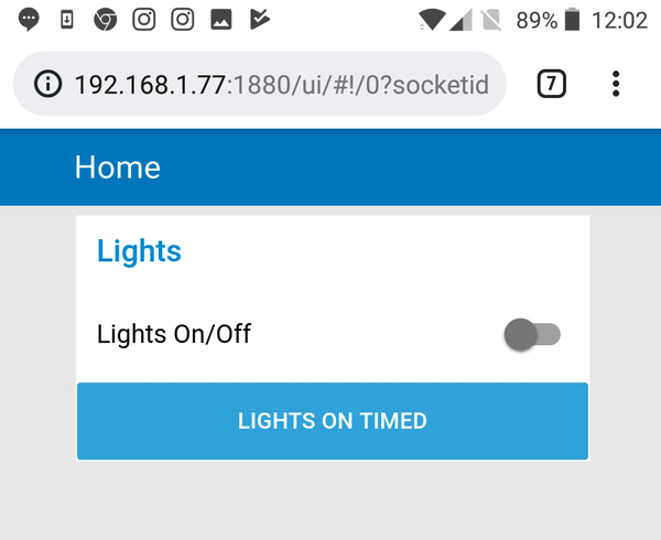
Figure 17-29. A web interface for controlling lights
See Also
For the full documentation on Node-RED, see https://nodered.org/docs.
17.8 Scheduled Events with Node-RED
Solution
Use the Node-RED inject node.
The flow shown in Figure 17-30 is based on the flows of Recipe 17.6. If you want to import the flow rather than build it up from scratch, you can find it at https://oreil.ly/EVCiX. Follow the instructions in the Discussion section of Recipe 17.2 to import the flow.

Figure 17-30. Using an inject node to schedule actions
A dashboard switch is used to turn the Sonoff (assumed to be switching a light) on and off, but in addition, there is an inject node (Auto Off) that is configured to inject a message of 0 to the “Sonoff_1” MQTT node. Figure 17-31 shows the configuration for the inject node.

Figure 17-31. Configuring a Node-RED inject node as a timed event
Discussion
If you had a number of Sonoff switches connected to appliances all around your house, one inject node could turn them all off by fanning out the message, as shown in Figure 17-32.

Figure 17-32. Switching off multiple devices
See Also
For full documentation on Node-RED, see https://nodered.org/docs/.
17.9 Publishing MQTT Messages from a Wemos D1
Solution
Use a low-cost ESP8266-based board like the Wemos D1 with customized software. Figure 17-33 shows a Wemos D1 with a Squid Button attached to one of its GPIO pins, powered by a USB power bank.
When the button is pressed, a message will be published to an MQTT server.

Figure 17-33. A Wemos D1 and Squid Button
To make this recipe, you will need the following:
A Wemos D1 mini (see “Modules”)
A Raspberry Squid Button (see “Modules”)
A USB power bank or other means of powering the Wemos D1
To be able to program the Wemos D1 from your Raspberry Pi, you need to install the Arduino integrated development environment (IDE) on your Raspberry Pi (Recipe 18.1) and then add support for the ESP8266 using Recipe 18.11.
Connect the Squid Button or other switch between the Wemos pin named D6 and GND.
Before you can use the sketch (the name for Arduino programs), you need to install an MQTT library into the Arduino IDE, so download the library as a ZIP file using the following commands:
$ cd /home/pi
$ wget https://github.com/knolleary/pubsubclient/archive/master.zip
Next, open the Arduino IDE, and then from the Sketch->Include Library menu, select Add ZIP Library. Navigate to the file master.zip that you just downloaded, and the library will be installed.
The Arduino program for this is available as part of the downloads for the book (see Recipe 3.22). You will find it in the folder called ch_17_web_switch, inside a folder at the same level as the python folder called arduino.
Open the sketch in the Arduino IDE by clicking ch_17_web_switch.ino. Set the board type to Wemos D1 and the serial port to /dev/ttyUSB0 (see Recipe 18.11).
Before uploading the sketch to the Arduino, you need to make a few changes to the code. Look for these lines near the top of the sketch:
const char* ssid = "your wifi access point name";
const char* password = "your wifi password";
const char* mqtt_server = "your MQTT IP address";
Replace the placeholder text for ssid, password, and mqtt_server with the appropriate values for your setup.
Then click the upload button in the Arduino IDE.
After you’ve programmed it, the Wemos does not need to be connected to your Raspberry Pi, so if you want, you can power it by some other means, such as a USB power bank. However, the sketch prints out useful debug information, so it’s worth staying tethered to your Raspberry Pi until you know everything is working. To see this information, open the Arduino IDE’s serial console (see Recipe 18.2), which should look something like Figure 17-34.

Figure 17-34. Using the Arduino serial monitor to view the Wemos output
To test the recipe, start a Terminal session on your Raspberry Pi and run the following command to subscribe to button presses:
$ mosquitto_sub -d -t button_1
Client mosqsub/5007-raspberryp sending CONNECT
Client mosqsub/5007-raspberryp received CONNACK
Client mosqsub/5007-raspberryp sending SUBSCRIBE (Mid: 1, Topic: button_1,
                                                  QoS: 0)
Client mosqsub/5007-raspberryp received SUBACK
Subscribed (mid: 1): 0
Client mosqsub/5007-raspberryp received PUBLISH (d0, q0, r0, m0, 'button_1', ...
                                                 (16 bytes))
Button 1 pressed
Now every time you press the button, the message Button 1 pressed should appear in the Terminal.
Discussion
This is a book about Raspberry Pi, not Arduino, so we won’t go through the Arduino C code in any detail.
The code is based on the example sketch called mqtt_basic in the library PubSubClient. As well as the constants at the top of the file for your WiFi credentials, the lines
constchar*topic="button_1";constchar*message="Button 1 pressed";
might also be of interest. They determine the MQTT topic to be used and the message to accompany published events. You could program an entire series of Wemos buttons with different topics and messages.
See Also
To use your newly configured Wemos with Node-RED, see Recipe 17.10.
You will learn much more about devices like the Wemos in Chapter 18.
17.10 Using a Wemos D1 with Node-RED
Solution
As an example, we can use the Wemos WiFi button from Recipe 17.9 in a Node-RED flow to toggle a Sonoff web switch (Recipe 17.4) on and off.
Figure 17-35 shows the Node-RED flow for this. If you want to import the flow rather than build it up from scratch, you can find the flow at https://oreil.ly/aIdtv. Follow the instructions in the Discussion section of Recipe 17.2 to import the flow.

Figure 17-35. A Node-RED flow for a WiFi light switch
To make this recipe, you will benefit from having already tried all the previous recipes in this chapter, as well as Recipe 18.11.
The Button 1 MQTT node subscribes to messages from the Wemos D1. Figure 17-36 shows the settings for this node.

Figure 17-36. Configuring the Button 1 node
The important thing here is that the Topic is set to “button_1.” The Trigger node works in the same way as in Recipe 17.6. The Trigger node is more interesting because this node remembers a value, which can be a 1 or a 0, and flips this value each time a message passes through it. This has to be done as a general function with a little bit of JavaScript code that remembers the state and toggles it. Figure 17-37 shows the node’s configuration including the code. This is a useful function that you will probably find yourself reusing in other projects.

Figure 17-37. The Toggle function
Discussion
Node-RED is a powerful way to quickly put together a home automation system. If you are used to a conventional programming language, this way of doing things takes a little getting used to; however, when you’ve mastered it, you won’t want to go back to writing reams of code.
There are lots of other interesting nodes in Node-RED’s palette, so take some time to explore them. Hovering over a node will display details about what it does, and you can follow this up by dragging the node onto a flow and trying it out.
See Also
For full documentation on Node-RED, see https://nodered.org/docs.