
Chapter 10. Controlling Hardware
10.0 Introduction
In this chapter, you come to grips with the control of electronics through the Raspberry Pi’s general-purpose input/output (GPIO) connector.
Most of the recipes require the use of a solderless breadboard and male-to-female and male-to-male jumper wires (see Recipe 9.8). To maintain compatibility with older 26-pin Raspberry Pi models, all the breadboard examples here use only the top 26 pins common to both GPIO layouts (see Recipe 9.1).
10.1 Connecting an LED
Solution
Connect an LED to one of the GPIO pins using a 470Ω or 1kΩ series resistor to limit the current. To make this recipe, you will need the following:
-
Breadboard and jumper wires (see “Prototyping Equipment and Kits”)
-
470Ω resistor (see “Resistors and Capacitors”)
-
LED (see “Opto-Electronics”)
Figure 10-1 shows how you can wire this LED using a solderless breadboard and male-to-female jumper leads.

Figure 10-1. Connecting an LED to a Raspberry Pi
Having connected the LED, we need to be able to turn it on and off using commands from Python.
Start a Python console from the Terminal and enter these commands:
$ sudo python3
>>> from gpiozero import LED
>>> led = LED(18)
>>> led.on()
>>> led.off()
>>>
This will turn your LED on after the led.on() command, and off again after the led.off() command.
Discussion
LEDs are a very useful, cheap, and efficient way of producing light, but you do have to be careful how you use them. If they are connected directly to a voltage source (such as a GPIO output) that is greater than about 1.7 volts, they will draw a very large current. This can often be enough to destroy the LED or whatever is providing the current—which is not good if your Raspberry Pi is providing the current.
You should always use a series resistor with an LED because the series resistor is placed between the LED and the voltage source, which limits the amount of current flowing through the LED to a level that is safe for both the LED and the GPIO pin driving it.
Raspberry Pi GPIO pins are guaranteed to provide only about 3mA or 16mA of current (depending on the board and number of pins in use)—see Recipe 9.2. LEDs will generally illuminate with any current greater than 1mA, but they will be brighter with more current. Use Table 10-1 as a guide to selecting a series resistor based on the type of LED; the table also indicates the approximate current that will be drawn from the GPIO pin.
| LED type | Resistor | Current (mA) |
|---|---|---|
|
Red |
470Ω |
3.5 |
|
Red |
1kΩ |
1.5 |
|
Orange, yellow, green |
470Ω |
2 |
|
Orange, yellow, green |
1kΩ |
1 |
|
Blue, white |
100Ω |
3 |
|
Blue, white |
270Ω |
1 |
As you can see, in all cases it is safe to use a 470Ω resistor. If you are using a blue or white LED, you can reduce the value of the series resistor considerably without risk of damaging your Raspberry Pi.
If you want to extend the experiments that you made in the Python console into a program that makes the LED blink on and off repeatedly, you could paste the code that you’ll find in ch_10_led_blink.py into an editor (as with all the program examples in this book, you can download this program [see Recipe 3.22]):
fromgpiozeroimportLEDfromtimeimportsleepled=LED(18)whileTrue:led.on()sleep(0.5)led.off()sleep(0.5)
To run the command, enter the following:
$ python3 ch_10_led_blink.py
The sleep period of 0.5 seconds between turning the LED on and turning it off again makes the LED blink once a second.
The LED class also has a built-in method for blinking, as illustrated by this example:
fromgpiozeroimportLEDled=LED(18)led.blink(0.5,0.5,background=False)
The first two parameters to blink are the on time and off time, respectively. The optional background parameter is interesting because if you set this to True, your program will be able to continue running other commands in the background while the LED is blinking.
When you are ready to stop the LED blinking in the background, you can just use led.off(). This technique can greatly simplify your programs. The example in the file ch_10_led_blink_2.py shows this in action:
fromgpiozeroimportLEDled=LED(18)led.blink(0.5,0.5,background=True)("Notice that control has moved away - hit Enter to continue")input()("Control is now back")led.off()input()
When the program starts, the LED will be set blinking in the background and the program is free to move onto the next command and print Notice that control has moved away - hit Enter to continue. The input() command will cause the program to halt and wait for input (you can just press the Enter key). But notice that before you press Enter, the LED is still blinking even though the program has moved on to wait for input.
When you do press Enter again, the led.off() command stops the LED’s background blinking.
See Also
Check out this handy series resistor calculator.
For more information on using a breadboard and jumper wires with the Raspberry Pi, see Recipe 9.8.
See the gpiozero documentation on LEDs.
10.2 Leaving the GPIO Pins in a Safe State
Discussion
Earlier methods of accessing the GPIO pins such as the RPi.GPIO library did not automatically set the GPIO pins to be in a safe input state. Instead, they required you to call a cleanup function before exiting the program.
If cleanup was not called or the Pi was not rebooted, pins set to be outputs would remain as outputs after the program has finished. If you were to start wiring up a new project, unaware of this problem, your new circuit might accidentally short a GPIO output to one of the supply voltages or another GPIO pin in the opposite state. A typical scenario in which this might happen would be if you were to connect a push switch, connecting a GPIO pin that you had configured as an output and HIGH to GND.
Fortunately for us, the gpiozero library now takes care of this.
See Also
For more information on exception handling in Python, see Recipe 7.10.
10.3 Controlling the Brightness of an LED
Solution
The gpiozero library has a pulse-width modulation (PWM) feature that allows you to control the power to an LED and its brightness.
To try it out, connect an LED as described in Recipe 10.1 and run this test program (ch_10_led_brightness.py):
fromgpiozeroimportPWMLEDled=PWMLED(18)whileTrue:brightness_s=input("Enter Brightness (0.0 to 1.0):")brightness=float(brightness_s)led.value=brightness
The program is included in the code download (see Recipe 3.22).
Run the Python program, and you will be able to change the brightness by entering a number between 0.0 (off) and 1.0 (full brightness):
$ python ch_10_led_brightness.py
Enter Brightness (0.0 to 1.0):0.5
Enter Brightness (0.0 to 1.0):1
Enter Brightness (0.0 to 1.0):0
Exit the program by pressing Ctrl-c. Ctrl-c is command line for stop what you are doing; in many situations, it will stop a program entirely.
Note that when controlling an LED’s brightness like this, you must define the LED as being PWMLED and not just LED.
Discussion
PWM is a clever technique by which you vary the length of pulses while keeping the overall number of pulses per second (the frequency in Hz) constant. Figure 10-2 illustrates the basic principle of PWM.
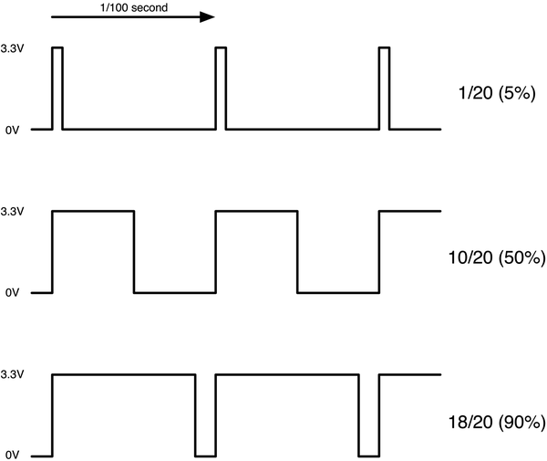
Figure 10-2. Pulse-width modulation
By default, the PWM frequency is 100Hz; that is, the LED flashes 100 times per second. You can change this where you define the PWMLED by supplying an optional parameter:
led=PWMLED(18,frequency=1000)
The value is in Hz, so in this case, the frequency is set to 1,000 Hz (1 kHz).
Table 10-2 compares frequencies specified in the parameter to the actual frequencies on the pin measured with an oscilloscope.
| Requested frequency | Measured frequency |
|---|---|
|
50 Hz |
50 Hz |
|
100 Hz |
98.7 Hz |
|
200 Hz |
195 Hz |
|
500 Hz |
470 Hz |
|
1 kHz |
880 Hz |
|
10 kHz |
4.2 kHz |
You can see that the frequency becomes less accurate as it increases. This means that this PWM feature is no good for audio but plenty fast enough for controlling the brightness of LEDs or the speed of motors. If you want to experiment with this yourself, the program is in the code download and called ch_10_pwm_f_test.py.
See Also
For more information on PWM, see Wikipedia.
Recipe 10.10 uses PWM to change the color of an RGB LED, and Recipe 11.4 uses PWM to control the speed of a DC motor.
For more information on using a breadboard and jumper wires with the Raspberry Pi, see Recipe 9.8. You can also control the brightness of the LED with a slider control—see Recipe 10.9.
10.4 Switching a High-Power DC Device Using a Transistor
Solution
These high-power LEDs use far too much current to light directly from a GPIO pin. They also require 12V rather than the 3.3V. To control such a high-power load, you need to use a transistor.
In this case, you will use a high-power type of transistor called a metal–oxide–semiconductor field-effect transistor (MOSFET), which costs less than a dollar but can handle loads up to 30 amps—many times more than is required for the high-power LEDs. The MOSFET used is a FQP30N06L (see “Transistors and Diodes”).
Figure 10-3 shows how you can connect a MOSFET on a breadboard. Make sure that you correctly identify the positive and negative supply leads for the LED module.
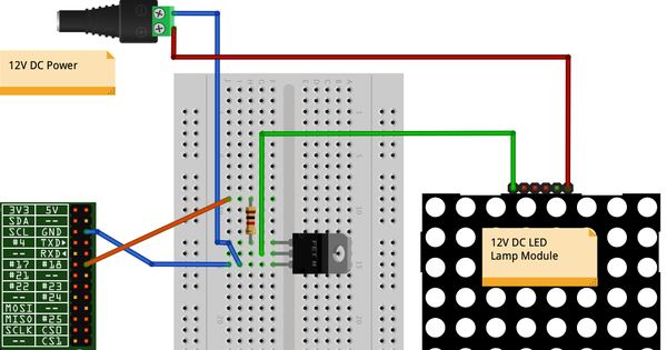
Figure 10-3. Controlling large currents with a MOSFET
To make this recipe, you will need the following:
-
Breadboard and jumper wires (see “Prototyping Equipment and Kits”)
-
1kΩ resistor (see “Resistors and Capacitors”)
-
FQP30N06L N-Channel MOSFET or TIP120 Darlington transistor (see “Transistors and Diodes”)
-
12V power adapter
-
12V DC LED module
The Python code to turn the LED panel on and off is exactly the same as if we were controlling a single low-power LED without the MOSFET (see Recipe 10.1).
You can also use PWM with the MOSFET to control the brightness of the LED module (see Recipe 10.3).
Discussion
Whenever you need to power anything significant using the GPIO connector, use batteries or an external power adapter. The GPIO connector can supply only relatively low currents (Recipe 9.2). In this case, you’ll use a 12V DC power adapter to provide the power to the LED panel. Pick a power adapter that has sufficient power handling. Thus, if the LED module is 5W, you need at least a 12V 5W power supply (6W would be better). If the power supply specifies a maximum current rather than power, you can calculate its power by multiplying the voltage by the maximum current. For instance, a 500mA 12V power supply can provide 6W of power.
The resistor is necessary to ensure that the peak currents that occur as the MOSFET switches from off to on, and vice versa, do not overload the GPIO pin. The MOSFET switches the negative side of the LED panel, so the positive supply is connected directly to the positive side of the LED panel, and the negative side of the LED panel is connected to the drain of the MOSFET. The source connection of the MOSFET is connected to GND, and the MOSFET’s gate pin controls the flow of current from the drain to the source. If gate voltage is above 2V or so, the MOSFET will turn on, and current flows through both it and the LED module.
The MOSFET used here is an FQP30N06L. The L at the end means that it is a logic-level MOSFET whose gate threshold voltage is suitable for use with 3.3V digital outputs. The non-L version of this MOSFET is also likely to work just fine, but you cannot guarantee that it will, as the specified range of gate threshold voltages is 2V to 4V. Therefore, if you were unlucky and got a MOSFET at the 4V end, it would not switch well.
An alternative to using a MOSFET is to use a power Darlington transistor like the TIP120. This has a compatible pinout with the FQP30N06L, so you can keep the same breadboard layout.
This circuit is suitable for controlling the power to other low-voltage DC devices. The only real exceptions are motors and relays, which require some extra treatment (see Recipe 10.5).
See Also
Check out the datasheet for the MOSFET.
If you would like to create a graphical user interface with which to control your LED module, see Recipe 10.8 for simple on/off control, and Recipe 10.9 for variable control of the brightness with a slider.
10.5 Switching a High-Power Device Using a Relay
Solution
Use a relay and small transistor.
Figure 10-4 shows how you can connect a transistor and relay on a breadboard. Make sure that both the transistor and diode are placed the right way. The diode has a stripe at one end, and the transistor used here has flat one side and one curved side.
To make this recipe, you will need the following:
-
Breadboard and jumper wires (see “Prototyping Equipment and Kits”)
-
1kΩ resistor (see “Resistors and Capacitors”)
-
Transistor 2N3904 (see “Transistors and Diodes”)
-
1N4001 diode (see “Transistors and Diodes”)
-
5V relay (see “Miscellaneous”)
-
Multimeter
You can use the same LED blink program that you used in Recipe 10.1. If all is well, you’ll hear a click from the relay and a beep from the multimeter each time the contacts are closed. However, relays are slow mechanical devices, so don’t try to use them with pulse-width modulation (PWM): it can damage the relay.
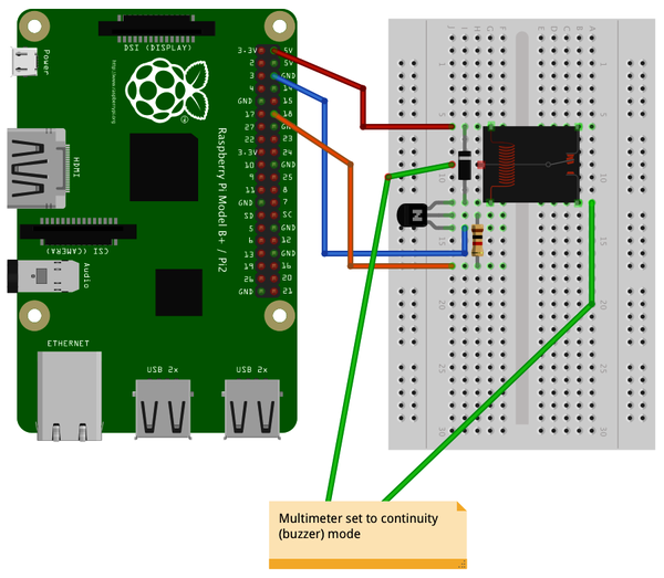
Figure 10-4. Using a relay with a Raspberry Pi
Discussion
Relays have been around since the early days of electronics and have the great advantage of being easy to use, plus they’ll work in any situation where a switch would normally work—for example, when you’re switching AC (alternating current), or in situations for which the exact wiring of the device being switched is unknown.
If the relay contacts are asked to exceed their specifications, the relay’s life will be shortened. There will be arcing, and the contacts can eventually fuse together. There is also the possibility of the relay becoming dangerously hot. When in doubt, overspecify the relay contacts.
Figure 10-5 shows the schematic symbol, pin layout, and package of a typical relay.
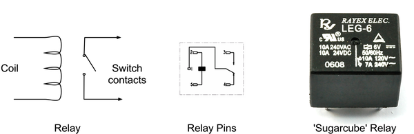
Figure 10-5. The workings of a relay
A relay is essentially a switch whose contacts are closed when an electromagnet pulls them together. Because the electromagnet and switch are not connected electrically in any way, this protects the circuit driving the relay coil from any high voltages on the switch side.
The downside of relays is that they are slow to operate and will eventually wear out after many hundreds of thousands of operations. This means they are suitable only for slow on/off control, and not for fast switching like PWM.
The coil of a relay requires about 50mA to close the connections. Because a Raspberry Pi GPIO pin is capable of supplying only about 3mA, you need to use a small transistor as a switch. You don’t need to use a high-power MOSFET like you did in Recipe 10.4; you can just use a small transistor instead. This has three connections. The base (middle lead) is connected to the GPIO pin via a 1kΩ resistor to limit the current. The emitter is connected to GND, and the collector is connected to one side of the relay. The other side of the relay is connected to 5V on the GPIO connector. The diode is used to suppress any high-voltage pulses that occur when the transistor rapidly switches the power to the relay’s coil.
Warning
Although relays can be used to switch 110V or 240V AC, this voltage is very dangerous and should not be used on a breadboard. If you want to switch high voltages, use Recipe 10.6 instead.
See Also
For switching direct current (DC) using a power MOSFET, see Recipe 10.4.
10.6 Controlling High-Voltage AC Devices
Solution
Use a PowerSwitch Tail II (see Figure 10-6). This handy device makes it really safe and easy to switch AC equipment on and off from a Raspberry Pi. It has an AC socket on one end and a plug on the other, like an extension cable; the only difference is that the control box in the middle of the lead has three screw terminals. By attaching terminal 2 to GND and terminal 1 to a GPIO pin, the device acts like a switch to turn the appliance on and off.
You can use the same Python code that you did in Recipe 10.1 to use the PowerSwitch Tail, as shown in Figure 10-6.
Discussion
The PowerSwitch Tail uses a relay, but to switch the relay, it uses a component called an opto-isolator, which has an LED shining onto a photo-TRIAC (a high-voltage, light-sensitive switch); when the LED is illuminated, the photo-TRIAC conducts, supplying current to the relay coil.
The LED inside the opto-isolator has its current limited by a resistor so that only 3mA flows through it when you supply it with 3.3V from a GPIO pin.
You will also find devices similar to but less expensive than the PowerSwitch Tail for sale on eBay and Amazon.
See Also
For switching DC using a power MOSFET, see Recipe 10.4; for switching using a relay on a breadboard, see Recipe 10.5.
A 240V version of the PowerSwitch Tail is available as a kit.

Figure 10-6. Using a PowerSwitch Tail with Raspberry Pi
10.7 Controlling Hardware with Android and Bluetooth
Solution
Use the free Blue Dot Android app and Python library:
$ sudo pip3 install bluedot
Next, you need to make sure that your Raspberry Pi is discoverable. In the upper-right corner of the Raspberry Pi’s screen, click the Bluetooth icon, and then click Make Discoverable (Figure 10-7).

Figure 10-7. Making your Raspberry Pi discoverable in Bluetooth
Next, you need to pair your Raspberry Pi and phone. Make sure that your phone has Bluetooth turned on, and then click Add New Device on your Raspberry Pi’s Bluetooth menu (Figure 10-8).

Figure 10-8. Pairing your Raspberry Pi and Phone
Find your phone in the list and then click Pair. You then are prompted on your phone to confirm a code to complete the pairing.
When pairing is complete, go to the Play Store app on your phone. Search for and install the Blue Dot app. The app won’t be able to work with your phone until you run a Python program that uses the Python Blue Dot code to listen for commands, so run the following program (ch_10_bluedot.py) on your Raspberry Pi:
frombluedotimportBlueDotbd=BlueDot()whileTrue:bd.wait_for_press()("You pressed the blue dot!")
As with all the program examples in this book, you can download this program (see Recipe 3.22).
Now it’s time to open the Blue Dot app on your phone. When you do this, it provides a list of Blue Dot devices (Figure 10-9).

Figure 10-9. Connecting to your Raspberry Pi with Blue Dot
After you’re connected, the eponymous blue dot will appear, as shown in Figure 10-10.

Figure 10-10. The blue dot
When you tap on the Blue Dot with your finger, your Python program will print out the message: You pressed the blue dot!
$ python3 ch_10_bluedot.py
Server started B8:27:EB:D5:6C:E9
Waiting for connection
Client connected C0:EE:FB:F0:94:8F
You pressed the blue dot!
You pressed the blue dot!
You pressed the blue dot!
Discussion
The big blue dot isn’t just a button; you can also use it as a joystick. You can slide, swipe, and rotate the dot.
The Blue Dot library allows you to link handler functions to events such as swiping and rotating. For more information on this, take a look at the documentation.
See Also
For full information on Blue Dot, see their website.
There is also a Blue Dot Python module that lets you use a second Raspberry Pi as the Blue Dot remote.
See Recipe 1.18 for more information on using Bluetooth with a Raspberry Pi.
10.8 Making a User Interface to Turn Things On and Off
Solution
Use guizero to provide the user interface for gpiozero to turn the pin on and off (Figure 10-11).

Figure 10-11. An on/off switch in guizero
If you haven’t already done so, install guizero using the following command:
$ sudo pip3 install guizero
You’ll need to connect an LED or some other kind of output device to GPIO pin 18. Using an LED (Recipe 10.1) is the easiest option for getting started.
As with all the program examples in this book, you can download the code for this recipe (see Recipe 3.22). The file is called ch_10_gui_switch.py and creates the switch shown in Figure 10-11:
fromgpiozeroimportDigitalOutputDevicefromguizeroimportApp,PushButtonpin=DigitalOutputDevice(18)defstart():start_button.disable()stop_button.enable()pin.on()defstop():start_button.enable()stop_button.disable()pin.off()app=App(width=100,height=150)start_button=PushButton(app,command=start,text="On")start_button.text_size=30stop_button=PushButton(app,command=stop,text="Off",enabled=False)stop_button.text_size=30app.display()
Discussion
The example uses a pair of buttons, and when you press one, it disables itself and enables its counterpart. It also uses gpiozero to change the state of the output pin using the on() and off() methods.
This example would work just the same if we used the line pin = LED(18) rather than pin = DigitalOutputDevice(18), but using DigitalOutputDevice keeps things more generic. After all, you could be controlling anything from pin 18, not just an LED.
See Also
You can can also use this program to control a high-power DC device (Recipe 10.4), a relay (Recipe 10.5), or a high-voltage AC device (Recipe 10.6).
For more information on guizero, see Recipe 7.22.
10.9 Making a User Interface to Control PWM Power for LEDs and Motors
Solution
Using the gpiozero and guizero user interface framework, write a Python program that uses a slider to change the PWM duty cycle between 0 and 100% (Figure 10-12).

Figure 10-12. User interface for controlling PWM power
You will need to connect an LED or some other kind of output device to GPIO pin 18 that is capable of responding to a PWM signal. Using an LED (Recipe 10.1) is the easiest option to start with.
Open an editor and paste in the following code (the name of the file is ch_10_gui_slider.py):
fromgpiozeroimportPWMOutputDevicefromguizeroimportApp,Sliderpin=PWMOutputDevice(18)defslider_changed(percent):pin.value=int(percent)/100app=App(title='PWM',width=500,height=150)slider=Slider(app,command=slider_changed,width='fill',height=50)slider.text_size=30app.display()
As with all the program examples in this book, you can download the code for this recipe (see Recipe 3.22).
Run the program using the following command:
$ python3 gui_slider.py
Discussion
The example program uses the Slider class. The command option runs the slider_changed command every time the value of the slider is changed. This updates the value of the output pin. The parameter to the slider_changed function is a string, even though it contains a number between 0 and 100, so int is used to convert it into a number and then the percent value has to be divided by 100 to give a value between 0 and 1 for the PWM output.
See Also
You can use this program to control an LED (Recipe 10.1), a DC motor (Recipe 11.4), or a high-power DC device (Recipe 10.4).
10.10 Changing the Color of an RGB LED
Solution
Use PWM to control the power to each of the red, green, and blue channels of an RGB LED.
To make this recipe, you will need the following:
-
Breadboard and jumper wires (see “Prototyping Equipment and Kits”)
-
Three 470Ω resistors (see “Resistors and Capacitors”)
-
RGB common cathode LED (see “Opto-Electronics”)
-
A Perma-Proto (Recipe 9.9) or Pi Plate (see Recipe 9.19) to make a more permanent project (optional)
Figure 10-13 shows how you can connect your RGB LED on a breadboard. Make sure that the LED is the correct way around; the longest lead should be the second lead from the top of the breadboard. This connection is called the common cathode because the negative connections (cathodes) of the red, green, and blue LEDs within the LED case have all their negative sides connected together to reduce the number of pins needed in the package.
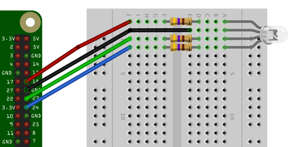
Figure 10-13. Using a RGB LED with a Raspberry Pi
An alternative to using a breadboard is to use a Raspberry Squid (see Recipe 9.10).
The upcoming program has three sliders to control the red, green, and blue channels of the LED (Figure 10-14).

Figure 10-14. Using a user interface to control an RGB LED
Open an editor and paste in the following code (the file is called ch_10_gui_slider_RGB.py):
fromgpiozeroimportRGBLEDfromguizeroimportApp,SliderfromcolorzeroimportColorrgb_led=RGBLED(18,23,24)red=0green=0blue=0defred_changed(value):globalredred=int(value)rgb_led.color=Color(red,green,blue)defgreen_changed(value):globalgreengreen=int(value)rgb_led.color=Color(red,green,blue)defblue_changed(value):globalblueblue=int(value)rgb_led.color=Color(red,green,blue)app=App(title='RGB LED',width=500,height=400)Slider(app,command=red_changed,end=255,width='fill',height=50).text_size=30Slider(app,command=green_changed,end=255,width='fill',height=50).text_size=30Slider(app,command=blue_changed,end=255,width='fill',height=50).text_size=30app.display()
As with all the program examples in this book, you can download the code for this recipe (see Recipe 3.22).
Discussion
The code is similar in operation to the control for a single PWM channel, described in Recipe 10.9. However, in this case, you need three PWM channels and three sliders, one for each color.
The type of RGB LED used here is a common cathode. If you have the common anode type, you can still use it, but connect the common anode to the 3.3V pin on the GPIO connector. You will then find that the slider becomes reversed, so a setting of 255 becomes off and 0 becomes full on.
When you are selecting an LED for this project, LEDs labeled diffused are best because they allow the colors to be mixed better.
See Also
If you want to control just one PWM channel, see Recipe 10.9.
For another approach to controlling the color of an RGB LED using the Squid RGB LED library, see Recipe 9.10.
10.11 Using an Analog Meter as a Display
Solution
Assuming you have a 5V voltmeter, you can use a PWM output to drive the meter directly, connecting the negative side of the meter to ground and the positive side to a GPIO pin (Figure 10-15). If the meter is the common 5V kind, you’ll only be able to display voltages up to 3.3V.
If you want to use almost the full range of a 5V voltmeter, you will need a transistor to act as a switch for the PWM signal and a 1kΩ resistor to limit the current to the base of the transistor.
To make this recipe, you will need the following:
-
5V panel meter (see “Miscellaneous”)
-
Breadboard and jumper wires (see “Prototyping Equipment and Kits”)
-
Two 1kΩ resistors (see “Resistors and Capacitors”)
-
Transistor 2N3904 (see “Transistors and Diodes”)
Figure 10-16 shows the breadboard layout for this.

Figure 10-15. Connecting a voltmeter directly to a GPIO pin
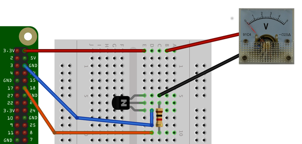
Figure 10-16. Using a 5V panel meter with 3.3V GPIO
Discussion
To test the voltmeter, use the same program as you did for controlling the brightness of the LED in Recipe 10.9.
You will probably notice that the needle gives a steady reading at either end of the scale, but everywhere else it jitters a bit. This is a side effect of the way the PWM signals are generated. For a steadier result, you can use external PWM hardware like the 16-channel module used in Recipe 11.3.
See Also
For more information about how old-fashioned voltmeters work, see Wikipedia.
For more information on using a breadboard and jumper wires with the Raspberry Pi, see Recipe 9.8.