
Arduino and Raspberry Pi are two of the most popular embedded systems on the market today. Sometimes, their names and capabilities are discussed interchangeably, but each platform has its own unique capabilities and usage. In robotics, it is important to know the merits of each of these powerful devices and how each one can be used with ROS to inherit the advantages of ROS.
Rosserial defines the protocol for ROS communication over serial transmission lines to ROS nodes running on microcontrollers or single-board computers. Standard ROS messages are serialized/deserialized in a prescribed format, and topics and services are multiplexed for serial ports or network sockets. For low-level details of this protocol, refer to http://wiki.ros.org/rosserial/Overview/Protocol.
In the following section, the capability of rosserial is demonstrated in an example program using Arduino and an ultrasonic sensor.
The Arduino board contains a microcontroller that can process one ROS node at a time. This sequential nature makes it easy to use and understand its processing and communication with external devices, such as motors, sensors, and peripheral devices. Arduino has a set of digital and analog input/output (I/O) pins to interface with a wide variety of external sensors and actuators. This simple board can be used to design and build a robot to sense and move about in its environment or to enhance an existing robot with extended capabilities.
Interfacing the Arduino board to an external computer allows you to program the microcontroller using its own Arduino IDE based on the external computer. Programs developed in C in the Arduino IDE are downloaded to the microcontroller over its USB connection using its serial communications interface.
The Arduino IDE allows quick and easy programming of Arduino boards. This open source software can be installed on Windows, macOS, and Linux operating systems. The IDE can generate software for any Arduino board, but check for special instructions for your particular board at https://www.arduino.cc/en/Guide/HomePage.
To install the Arduino IDE as Debian packages on your Ubuntu operating system, open a terminal window and enter the following commands:
$ sudo apt-get update
$ sudo apt-get install arduino arduino-core
If any additional information is needed, refer to http://playground.arduino.cc/Linux/Debian.
For installation instructions on how to manually load Arduino, refer to the Downloading and maintaining manually section of http://playground.arduino.cc/Linux/Ubuntu.
The latest software download can be found at https://www.arduino.cc/en/Main/Software.
Arduino offers extensive documentation guides, tutorials, and examples at the following websites:
Next, we will install the ROS software for Arduino.
The rosserial_arduino package allows you to implement the ROS communication protocol over Arduino's serial ports. This package helps the software implement ROS messages, access ROS system time, and publish tf transforms. Using the rosserial_arduino package, an independent ROS node running on your Arduino can publish and subscribe to messages from ROS nodes running on a remote computer.
To load the rosserial_arduino package on your computer, use the following installation commands:
$ sudo apt-get install ros-kinetic-rosserial-arduino
$ sudo apt-get install ros-kinetic-rosserial
The rosserial metapackage contains the rosserial_msgs, rosserial_client, and rosserial_python packages. The rosserial_python package is used to provide the remote computer serial interface to communicate with the Arduino node.
ROS bindings for Arduino are implemented as an Arduino library within the IDE. This library, ros_lib, must be added to the /libraries subdirectory within the user's Arduino sketchbook (the code directory). We are using ~/sketchbook as the directory in which to store our Arduino code (sketches). The subdirectory /libraries should already exist, or should be created within your sketchbook. Change to this subdirectory with the following command (<sketchbook> is the path to your sketchbook directory):
$ cd <sketchbook>/libraries
If the ros_lib library already exists, delete it with this command:
$ rm -rf ros_lib
To generate the ros_lib library, type the following command:
$ rosrun rosserial_arduino make_libraries.py
This command will create a ros_lib subdirectory and a number of subdirectories under ros_lib. A ros_lib subdirectory is a wrapper for ROS messages and services implemented with Arduino data types. The Arduino C/C++ data types are converted by ros_lib through the use of special header files. We will use some of these header files in our example with the ultrasound sensor. For now, the subdirectory we are interested in is /examples. Type the following commands:
$ cd <sketchbook>/libraries/ros_lib/examples/
$ ls
Verify that the contents are similar to the following files:
ADC     button_example  IrRanger  pubsub       ServoControl  Ultrasound
Blink    Clapper          Logging   ServiceClient  Temperature
BlinkM  HelloWorld      Odom     ServiceServer  TimeTF
These files contain examples of the ROS–Arduino code. The examples are used to provide a basic implementation of ROS on Arduino. For example, the Temperature code can be used to read the temperature values of a sensor connected to the Arduino board. You can start with the examples and modify them to suit your particular application.
Next, with your Arduino board plugged into the USB port of the computer, start the Arduino IDE with this command:
$ arduino
The Arduino Permission Checker may appear in a pop-up window, stating that You need to be added to the dialout group. It is important that you click on the Add button and authenticate the selection with a password. An alternative is to enter the following command to assign yourself to the dialout group:
$ sudo usermod -a -G dialout <username>
Administrative privileges are necessary to perform either of these actions.
Check that your screen looks as follows as a result of the arduino command:

Arduino sketchbook
Verify that you can access the ros_lib examples by navigating the drop-down menus, File | Examples | ros_lib, as shown in the following screenshot:
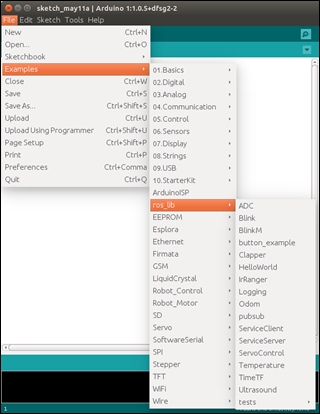
Arduino ros_lib installed
Also, check the serial port connection to the Arduino board. To list the available serial ports on your computer, use the following command:
$ ls /dev/tty*
From the Arduino IDE drop-down menu, Tools | Serial Port, verify the serial port connection. Our Arduino is connected to /dev/ttyACM0, as shown in the following screenshot:
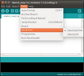
Connecting to a serial port
The ROS wiki presents a series of tutorials related to the rosserial_arduino package. These tutorials are listed and can be accessed from http://wiki.ros.org/rosserial_arduino/Tutorials.
The following example demonstrates the use of a ROS node running on Arduino publishing a sensor_msgs/Range message. This message contains distance data retrieved from an HC-SR04 ultrasonic sensor.
As an example of interfacing a sensor with the Arduino board, we will add an HC-SR04 ultrasonic range sensor. The following screenshot shows the face of the sensor:

HC-SR04 ultrasonic sensor
In operation, the sensor emits sound pulses well beyond the range of our hearing. If the pulses bounce off an obstacle, the returning sound wave is received by the sensor. Knowing the speed of sound in air as Velocity, it is possible to measure the time that the sound takes to reach the obstacle and return to the sensor, since the distance traveled by the sound waves to the object will be:
Time refers to the total time of travel of the sound wave in its two-way trip.
The speed of sound varies with temperature and other factors, but we will use the typical speed of sound in air at 20°C (68°F) to be 343 meters/second (1125.3 feet/second).
To use the sensor with the Arduino board, it is necessary to write code to trigger the sensor to emit the sound and then determine the time of travel of the sound wave. The distance between the sensor and an obstacle is determined from this time, as shown in the previous equation. The range of the HC-SR04 sensor is 2 cm to 400 cm, or from less than 1 inch to 13 ft.
Signals associated with the sensor are shown in the following diagram. The trigger pulse is created by the software as an output from the Arduino board digital pins to the Trig pin, shown in the preceding screenshot. The sensor sends out the sonic burst after the trigger pulse has ended. The echo signal on the Echo pin of the sensor when HIGH has a width that is proportional to the time the sound signal takes to be emitted and then returned. This signal is connected to a digital input pin of the Arduino board. Software is used to determine the length of the return echo pulse in microseconds. Then, the time in microseconds is converted into distance using the distance formula, as follows:
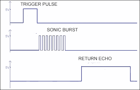
HC-SR04 sensor signals
According to the specifications of the HC-SR04 sensor, the trigger pulse created by the software must be at least 10 microseconds long. The repetition time to measure the distance to an obstacle must be greater than 25 milliseconds to ensure that the trigger pulses do not overlap in time with the return echo pulse. This is a repetition rate of 40 hertz. In the code to follow, the repetition time for the published range is set at 50 milliseconds.
For our setup, we used an Arduino UNO to interface with the HC-SR04 sensor. The following list describes the connections between the sensor pins and the pins of our Arduino UNO board:
The Arduino UNO is described at https://www.arduino.cc/en/main/arduinoBoardUno.
An Arduino sketch is provided to interface with the ultrasound sensor and determine the distance values detected by the sensor. The C code for the Arduino should be downloaded and stored in the <sketchbook>/ultrasound_sr04 directory as an .ino file.
Note
Downloading the ultrasound_sr04.ino code
You can download the example code files and other support material for this book from https://www.packtpub.com/ or at the website: https://github.com/FairchildC/ROS-Robotics-By-Example-2nd-Edition.
The following code performs these operations:
- Defines the pins of the Arduino board used for the sensor and outputs the trigger signal when the program runs
- Creates the node to publish range data indicating the distance between the sensor and an object
- Defines the ROS topic
/ultrasoundand causes the range data to be published when the code is run
The code is as follows:
/*
 * rosserial Ultrasound Example for HC-SR04
 */

#include <ros.h>
#include <ros/time.h>
#include <sensor_msgs/Range.h>

const int echoPin = 5;  //Echo pin
const int trigPin = 6;  //Trigger pin

const int maxRange = 400.0;   //Maximum range in centimeters
const int minRange = 0.0;     //Minimum range

unsigned long range_timer;    //Used to measure 50 ms interval

// instantiate node handle and publisher for
//  a sensor_msgs/Range message (topic name is /ultrasound)
ros::NodeHandle  nh;
sensor_msgs::Range range_msg;
ros::Publisher pub_range( "ultrasound", &range_msg);

/*
 * getRange() - This function reads the time duration of the echo
 *              and converts it to centimeters.
 */
float getRange(){
    int sample;      //Holds time in microseconds

    // Trigger pin goes low then high for 10 us then low
    //  to initiate the ultrasonic burst
    digitalWrite(trigPin, LOW);
    delayMicroseconds(2);

    digitalWrite(trigPin, HIGH);
    delayMicroseconds(10);
    digitalWrite(trigPin, LOW);

    // read pulse length in microseconds on the Echo pin
    sample = pulseIn(echoPin, HIGH);

    // sample in microseconds converted to centimeters
    // 343 m/s speed of sound;  time divided by 2
    return sample/58.3;
}

char frameid[] = "/ultrasound";   // global frame id string

void setup()
{
  // initialize the node and message publisher
  nh.initNode();
  nh.advertise(pub_range);

  // fill the description fields in the range_msg
  range_msg.radiation_type = sensor_msgs::Range::ULTRASOUND;
  range_msg.header.frame_id =  frameid;
  range_msg.field_of_view = 0.26;
  range_msg.min_range = minRange;
  range_msg.max_range = maxRange;

  // set the digital I/O pin modes
  pinMode(echoPin, INPUT);
  pinMode(trigPin, OUTPUT);
}

void loop()
{
  // sample the range data from the ultrasound sensor and
  // publish the range value once every 50 milliseconds
  if ( (millis()-range_timer) > 50){
    range_msg.range = getRange();
    range_msg.header.stamp = nh.now();
    pub_range.publish(&range_msg);
    range_timer =  millis() + 50;
  }
  nh.spinOnce();
}To open the Arduino IDE, type the following command:
$ arduino
From the menu bar, navigate the drop-down menus File | Sketchbook | ultrasound_sr04 to see the following screen:
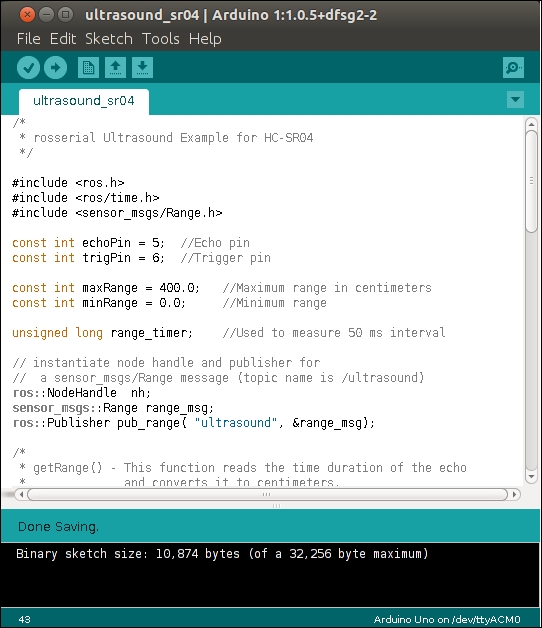
Arduino IDE with the ultrasound_sr04 code
On the toolbar menu, choose the right arrow icon to verify and upload the code to the Arduino board and wait for the Done uploading message.
In a second terminal window, start the ROS Master by typing:
$ roscore
In a third terminal window, execute the rosserial program by typing:
$ rosrun rosserial_python serial_node.py /dev/<ttyID>
Here, <ttyID> is the identifier of the serial port you are using.
Our system used /dev/ttyACM0, and our output yields the following information:
[INFO] [1505178855.571564]: ROS Serial Python Node
[INFO] [1505178855.574369]: Connecting to /dev/ttyACM0 at 57600 baud
[INFO] [1505178857.937858]: Note: publish buffer size is 280 bytes
[INFO] [1505178857.938173]: Setup publisher on ultrasound [sensor_msgs/Range]
The rosserial_python package contains a Python implementation to allow communication between a remote computer and an attached device capable of serial data transfer, such as the Arduino board. The serial_node.py script creates the/serial_node node.
The ROS data for distance will be published as range data. As the program executes, the range value and other information is published on the /ultrasound topic with the sensor_msgs/Range message. The message format can be seen by entering the following command in another terminal window:
$ rosmsg show sensor_msgs/Range
The output shows the message format as follows:
uint8 ULTRASOUND=0
uint8 INFRARED=1
std_msgs/Header header
  uint32 seq
  time stamp
  string frame_id
uint8 radiation_type
float32 field_of_view
float32 min_range
float32 max_range
float32 range
To see the numerical output of the /ultrasound topic, type this:
$ rostopic echo /ultrasound
The output should look similar to the following:
---
header:
  seq: 278
  stamp:
    secs: 1463092078
    nsecs:   3101881
  frame_id: /ultrasound
radiation_type: 0
field_of_view: 0.259999990463
min_range: 0.0
max_range: 400.0
range: 50.0
---
In the screen output, we see the information in the message. Note that the frame_id, radiation_type, field_of_view (0.26), min_range, and max_range variables were defined in the C code, which was shown previously. The range value is in centimeters and the values are published every 50 milliseconds.
To show the topic and range values in a graphical form, type the following command:
$ rqt_plot
The rqt_plot window is shown in the next screenshot. The values will of course depend on your setup and the distance between your sensor and the obstacle:

rqt plot of the range values in centimeters
In the screenshot, the range is a constant 50 cm and the max_range field is set to 400 cm, as defined in the code. The other values are too small to be seen on the scale.
In our test of the HC-SR04 sensor, we noticed some inaccuracies in the range measurements. As with any sensor like HC-SR04, the system should be calibrated and tested if you wish to ensure the accuracy of the measurement.
There are other sensors for ranging as well as for temperature measurement, motor control, and many other applications. A complete list of tutorials for Arduino applications using rosserial can be found at http://wiki.ros.org/rosserial_arduino/Tutorials.
rosserial can also be used to set up wireless communication using rosserial_xbee tools in order to create sensor networks using XBee devices and Arduino. More information on this is available at http://wiki.ros.org/rosserial_xbee.
The Raspberry Pi board is a general-purpose computer that contains a version of the Linux operating system called Raspbian. The Pi can process multiple ROS nodes at a time and can take advantage of many features of ROS. It can handle multiple tasks at a time and perform intense processing of images or complex algorithms.
There are several versions of Raspberry Pi available on the market. Each model is based on a Broadcom system on a chip (SOC) with an ARM processor and a VideoCore graphics processing unit (GPU). Models vary in the amount of board memory available, and a Secure Digital (SD) card is used for booting and long-term storage. Boards are available pre-configured with a variety of USB ports, HDMI and composite video output, RJ45 Ethernet, WiFi 802.11n, and Bluetooth communication.
To set up your Raspberry Pi and configure the Raspbian operating system, refer to these websites:
To configure your Raspberry Pi, see the website https://www.raspberrypi.org/documentation/configuration/.
To get started learning about Raspbian and interfacing with the general-purpose I/O, camera modules, and communication methods, refer to https://www.raspberrypi.org/documentation/usage/.
Technical documentation of the hardware is available at https://www.raspberrypi.org/documentation/hardware/.
The installation instructions for loading ROS Kinetic onto the Raspberry Pi can be found at http://wiki.ros.org/ROSberryPi/Installing%20ROS%20Kinetic%20on%20the%20Raspberry%20Pi.
These instructions are for a source installation of ROS onto a Raspberry Pi with the Raspian version Jessie installed for the operating system. A catkin workspace needs to be created for the source packages, and the ROS–Comm variation is recommended to install basic ROS packages, build tools, and communication libraries. Packages for GUI tools are not downloaded as part of this variation.
The projects you can undertake with the Raspberry Pi and ROS (sometimes called ROSberry Pi) are limitless. You can create programs in either Python or C++. A collection of examples can be found at these websites: