Considering Baxter's arms up to the wrist cuff, each arm has seven values that define the rotation angle of each joint. Since the link lengths and joint angles are known, it is possible to calculate the position and orientation of the gripper attached to the wrist. This approach to calculating the pose of the gripper, given the configuration of the arm is called forward kinematic analysis.
Fortunately, ROS has programs that allow the calculation and publishing of the joint angles, given a particular position and orientation of the gripper. The particular topic for Baxter is /robot/joint_states.
Baxter has seven joints in each of its two arms and two more joints in its head. The /robot/joint_states topic publishes the current joint states of the head pan (side-to-side) joint and the 14 arm joints. These joint states show position, velocity, and effort values for each of these joints. Joint position values are in radians, velocity values are in radians per second, and torque values are in Newton meters. The robot state publisher internally has a kinematic model of the robot. So, given the joint positions of the robot, the robot state publisher can compute and broadcast the 3D pose of each link in the robot.
For the examples in this section, it is assumed that Baxter Simulator is running, baxter_world is launched from baxter_gazebo, and the simulated robot is enabled:
$ cd baxter_ws
$ ./baxter.sh sim
$ roslaunch baxter_gazebo baxter_world.launch
In a second terminal, type the following commands:
$ cd baxter_ws
$ ./baxter.sh sim
$ rosrun baxter_tools enable_robot.py -e
Baxter's arms will be placed in the home position using the Python script presented previously via the following command:
$ python home_arms.py
The joint states will be displayed with the screen output edited to show the arm positions as angles of rotation in radians. To view one output of the joint states, type this:
$ rostopic echo /robot/joint_states –n1
Here is our output on the screen:
header:
  seq: 42448
  stamp:
    secs: 850
    nsecs: 553000000
  frame_id: ''

name: ['head_pan', 'l_gripper_l_finger_joint', 'l_gripper_r_finger_joint', 'left_e0', 'left_e1', 'left_s0', 'left_s1', 'left_w0', 'left_w1', 'left_w2', 'r_gripper_l_finger_joint', 'r_gripper_r_finger_joint', 'right_e0', 'right_e1', 'right_s0', 'right_s1', 'right_w0', 'right_w1', 'right_w2']

position: [9.642012118504795e-06 (Head),

Left: -9.409649977892339e-08, -0.02083311343765363, -1.171334885477055, 1.9312641121225074, -0.07941855421008803, -0.9965989736590268, 0.6650922280384437, 1.0314330310192892, -0.49634000104265397,

Right: 0.020833000098799456, 2.9266103072174966e-10, 1.1714460516466971, 1.9313701087550257, 0.07941788278369621, -0.9966421178258322, -0.6651529936706897, 1.0314155121179436, 0.49638770883940264]

velocity: [8.463358573117045e-09, 2.2845555643152853e-05, 2.766005018018799e-05, 6.96516608889685e-08, -1.4347584964474649e-07, 5.379243329637427e-08, -3.07783563763457e-08, -5.9625446169838476e-06, -2.765075210928186e-06, 4.37915209815064e-06, -1.9330586583769175e-08, -3.396963606705046e-08, -4.1024914575147146e-07, -6.470964538079114e-07, 1.2464164369422782e-07, -3.489373517131325e-08, 1.3838850846575283e-06, 1.1659521943505596e-06, -3.293066091641411e-06]

effort: [0.0, 0.0, 0.0, -0.12553439407980704, -0.16093410986695034, 1.538268268319598e-06, -0.1584186302672208, 0.0026223415490989055, -0.007023475006633362, -0.0002595722218323715, 0.0, 0.0, 0.12551329635801522, -0.16096013901023554, -1.4389475655463002e-05, -0.1583874287014453, -0.0026439994199378702, -0.0070054474078151685, 0.00024931690616014635]
Compare the radian values from home_arms.py and the result of rostopic echo of joint states, but watch the order of listing of the joints:
# store the home position of the arms
home_right = {'right_s0': 0.08, 'right_s1': -1.00, 'right_w0': -0.67, 'right_w1': 1.03, 'right_w2': 0.50, 'right_e0': 1.18, 'right_e1': 1.94}
home_left = {'left_s0': -0.08, 'left_s1': -1.00, 'left_w0': 0.67, 'left_w1': 1.03, 'left_w2': -0.50, 'left_e0': -1.18, 'left_e1': 1.94}
The velocity and effort (torque) terms are essentially zero, since Baxter's arms are not moving. Rounding off the arm joint position values to two places shows that the angular positions of the arm joints are equivalent to the values in the Python script.
We find the type of messages for joint states from sensor_msgs using this command:
$ rostopic type /robot/joint_states
The output is as follows:
sensor_msgs/JointState
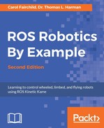
To show the home_arms pose for Baxter in Gazebo, follow these steps:
- Go to World | Models, click on baxter, and then select left_s0.
- Pull the Property window into view by clicking and dragging the three small ticks above this panel.
The figure should look like this:
Baxter home position
- Choose pose and look at the value of
angle_0:-0.07886530088. Rounded off, this isleft_s0: -0.08 selected inhome_arms.py. You can view other information by selecting another joint or link of Baxter from the World panel.
Another command shows the position and orientation of the end of the left arm:
$ rostopic echo /robot/limb/left/endpoint_state/pose -n1
The output should be similar to the following:
---
header:
  seq: 62403
  stamp:
    secs: 1249
    nsecs: 653000000
  frame_id: ''
pose:
  position:
    x: 0.582326339279
    y: 0.191017651504
    z: 0.111128161508
  orientation:
    x: 0.131168552915
    y: 0.991040351028
    z: 0.0117205349262
    w: 0.0222814367168
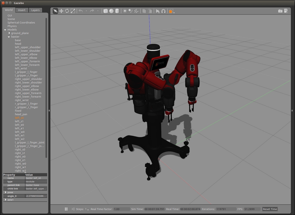
Yet another way to see the values is to start rqt and select Topics as Plugins and Topic Monitor. Select the /robot/limb/left/endpoint_state and /robot/limb/right/endpoint_state topics. The result is shown in the following screenshot:
Topic Monitor in rqt for endpoint states
The left arm's endpoint x, y, and z position agrees with the output from the rostopic echo command for the left endpoint_state topic. The right arm endpoint has the same x and z positions, but a negative value for y. This indicates that it is to the right of Baxter's vertical centerline.
Tf is a transform system used to keep track of the relation between different coordinate frames in ROS. The relationship between the coordinate frames is maintained in a tree structure that can be viewed. In Baxter's example, the robot has many coordinate frames that can be referenced to Baxter's base frame.
Tutorials about tf are given on the ROS wiki at http://wiki.ros.org/tf/Tutorials.
To demonstrate the use of tf, the following Baxter examples will be provided:
- Show tf in rviz after Baxter's arms are moved to a position in which the angles of the joints are zero
- Show various coordinate frames for Baxter's elements, such as cameras or grippers
With Baxter Simulator running (Gazebo), executing the Python script arms_to_zero_angles.py will move Baxter's arms to a position in which all the joint angles are zero.
The following code simply sets the joint angles to zero:
#!/usr/bin/env python   # arms_to_zero_angles.py
#
"""
Script to return Baxter's arms to a " zero" position
"""

# rospy - ROS Python API
import rospy

# baxter_interface - Baxter Python API
import baxter_interface

# initialize our ROS node, registering it with the Master
rospy.init_node('Zero_Arms')

# create instances of baxter_interface's Limb class
limb_right = baxter_interface.Limb('right')
limb_left = baxter_interface.Limb('left')

# store the zero position of the arms
zero_zero_right = {'right_s0': 0.0, 'right_s1': 0.00, 'right_w0': 0.00, 'right_w1': 0.00, 'right_w2': 0.00, 'right_e0': 0.00, 'right_e1': 0.00}
zero_zero_left = {'left_s0': 0.0, 'left_s1': 0.00, 'left_w0': 0.00, 'left_w1': 0.00, 'left_w2': 0.00, 'left_e0': 0.00, 'left_e1': 0.00}

# move both arms to zero position
limb_right.move_to_joint_positions(zero_zero_right)
limb_left.move_to_joint_positions(zero_zero_left)

quit()
Make the Python script executable:
$ chmod +x arms_to_zero_angles.py
Then, run the script:
$ python arms_to_zero_angles.py
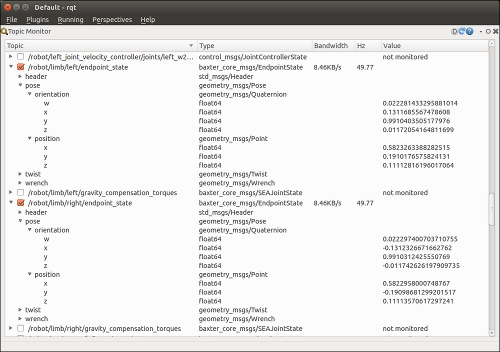
The position of the arms can be visualized in Gazebo and the values for position, velocity, and effort can be displayed. In the following Gazebo window, Baxter has arms outstretched at an angle from its torso:

Baxter's joints at zero degrees
The results of the joint states showing only the name and position are as follows:
---
header:
  seq: 120710
  stamp:
    secs: 2415
    nsecs: 793000000
  frame_id: ''

name: ['head_pan', 'l_gripper_l_finger_joint', 'l_gripper_r_finger_joint', 'left_e0', 'left_e1', 'left_s0', 'left_s1', 'left_w0', 'left_w1', 'left_w2', 'r_gripper_l_finger_joint', 'r_gripper_r_finger_joint', 'right_e0', 'right_e1', 'right_s0', 'right_s1', 'right_w0', 'right_w1', 'right_w2']

position: [2.1480795875383762e-05,
0.02083300010459807, 7.094235804419552e-09,
 -0.0052020885142498585, 0.008648349108503872, -0.0003526224733487737, -0.004363080957646481, 0.0029469234535000055, 0.004783709772852696, -0.0022098995590349446,
-4.685055459408831e-10, -0.02083300002921974, 0.005137618938708677, 0.008541712202397633, 0.0003482148331919177, -0.004308001456631239, -0.0029103069740452625, 0.004726431947482013, 0.002182588672263286]
Within numerical error tolerance, the values are zero for the arm joint angles.
You can send joint angles directly to Baxter using the JointCommand message from the baxter_core_messages package.
The JointCommand message is defined as follows:
int32 mode
float64[] command
string[] names

int32 POSITION_MODE=1
int32 VELOCITY_MODE=2
int32 TORQUE_MODE=3
int32 RAW_POSITION_MODE=4
The message defines the control mode, the command as an angle for the joints, and the names of the joints being controlled. The details of this are discussed on the following website:
http://sdk.rethinkrobotics.com/wiki/Arm_Control_Modes
As an example, move Baxter's arms into an arbitrary pose and then, to set the angles of four of Baxter's joints to zero using position control, type this command:
$ rostopic pub /robot/limb/left/joint_command baxter_core_msgs/JointCommand
"{mode: 1, command: [0.0, 0.0, 0.0, 0.0], names: ['left_w1', 'left_e1', 'left_s0', 'left_s1']}" -r 10
With Gazebo running and Baxter's arms in a zero-angle pose, start rviz:
$ rosrun rviz rviz
Now select the parameters for rviz:
- Select the field next to Fixed Frame (under Global Options) and select
base. - Select the Add button under the Displays panel, add Robot Model, and you will see Baxter appear.
- Select the Add button under the Displays panel, add TF, and see all the frames that are too complicated to use.
- Arrange the windows to see the left panel and the figure. Close the Views window on the right panel.
- Expand TF in the Displays panel by clicking on the triangle symbol on the left
- Under TF, expand Frames by clicking on the left triangle
- Uncheck the checkbox next to All Enabled
- Now, check
left_gripperto display the axes.
The rviz display looks similar to the following screenshot:
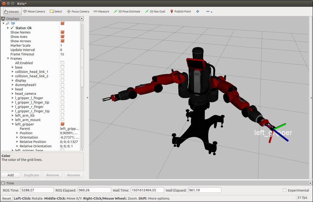
tf transform base and left gripper
You will see the left gripper axes in color on your screen: x is down (red), y is to the right (green), and z is forward (blue) in the preceding screenshot.
Now you can choose various elements of Baxter to see the tf coordinate axes.
The view_frames program can generate a PDF file with a graphical representation of the complete tf tree. To try the program, Baxter Simulator or the real Baxter should be communicating with the terminal window. To run view_frames, use the following command:
$ rosrun tf view_frames
In the current working folder, you should now have a file called frames.pdf. Open the file with the following command:
$ evince frames.pdf
More information about the tf frames can be found at http://wiki.ros.org/tf/Tutorials/Introduction%20to%20tf.