
Laser-induced soft matter organization and microstructuring of photonic materials
Abstract:
Laser radiation forces applied in fully transparent, highly entangled semi-dilute polymer solutions generate freestanding, threedimensional, micro- and, potentially, nano-solids. The underlying phenomena are attributed to a synergy of effects involving the radiation forces exerted by milliwatt laser beams on polymer chains and the entanglement of macromolecules. Most importantly, since the primary stages of formation, the incident optical field is structured and guided by the induced microstructures. This self-confinement enhances the effect and results in great compression of the material, osmotic solvent extraction and, eventually, materials solidification in free space. Structural reversibility verifies the absence of any chemical modification of the material. These innovative concepts are demonstrated through the fabrication of microstructures, including among others plasmonic and fluorescent semiconductor quantum–dot hybrid structures, as well as polymer fibers also drawn by laser radiation forces. The phenomenology of the involved effects is plausibly explained here and further research will resolve the fundamental aspects and lead the way forward to new and emerging concepts for future microfabrication technologies.
7.1 Introduction
Optical radiation exerts forces on matter and leads to the remarkable effects of optical trapping and organization pointing to applications in materials, information technology and biomedical sciences. Originating from the concept of optical trapping in the microscale (Neuman and Block 2004; Stevenson et al., 2010), the present chapter highlights current advances in assembly by laser-induced soft-matter organization. These emerging concepts provide alternative tools for micro- and potentially nano-fabrication and offer a new platform for fundamental investigations and new applications in photonics (Dholakia and Zemanek, 2010). Earlier investigations in this field (Loppinet et al., 2005; Sigel et al., 2002) had shown outstanding results concerning the organization of entangled soft matter upon illumination by a laser beam. These effects in liquid phase could not be fully explained at that stage. Later attempts investigated the formation of optical spatial solitons (Anyfantakis, 2008) and the effect of long time irradiation in the structure formation in polydiene solutions (Anyfantakis, 2010). The chapter presents an overview of laser-induced manipulation in entangled polymer solutions and introduces novel microfabrication applications.
In Section 7.2, the origins and physics of laser radiation forces are reviewed, highlighting the effects of optical forces applied in soft matter. In Section 7.3, polymer material dynamics aspects are discussed introducing polymer entanglement and reptation phenomena. In Section 7.4 of the chapter we overview the formation of microstructures due to radiation forces in several media, such as in bulk solutions, thin films, microfabrication in free space and fiber-drawing. The use of holographic outputs as an aiding tool for surface manipulation and concurrent multiple structure formation and the formation of plasmonic and quantum dot hybrid structures are also discussed. The chapter is summarized in Section 7.5 with the salient ideas of the chapter and comments on the emerging trends of laser-induced soft material organization and microstructuring. In the appendix, a thorough presentation on the material synthesis and characterization is given emphasizing the hybrid material synthesis.
7.2 The origin of radiation forces
Albeit that radiation pressure forces stem directly from Maxwell’s equation solutions for electric fields (Maxwell, 1873), it was many years later when a targeted attempt to handle and apply those forces on matter was reported by Ashkin (1970). In particular, the manipulation and trapping of particles by light radiation forces was first proposed by Ashkin (1970). Since then, significant work on the field has been done, evolving the concept of matter organization with the aid of optical tools (Ashkin 1978, 1992; Ashkin et al., 1986; Dienerowitz et al., 2008; Jonas and Zemanek, 2008).
Let us consider a beam propagating in a transparent medium. Once the beam faces an ‘obstacle’, for example a polymer micelle or a metal nanoparticle in a solution, it is scattered and changes direction (Fig. 7.1). Such a change gives rise to a momentum transfer from the beam to the obstacle. Considering the photon approximation for the light beam, it is obvious that each photon momentum is transferred to the object. According to Newton’s Second Law, we get:


that is, the rate of momentum change, associated with a change in momentum flux of the beam. It is understood, however, that if the particle is not on the beam propagation axis, that is, it is convergent or divergent, the momentum flux will be decreased.
Depending on the relative size of the particle as compared to the interacting wavelength this light–matter interaction can be approached in two regimes. First, in the Rayleigh regime particle size is much smaller than the wavelength of incident light. In that case, the particle acts as a simple point dipole and the radiation force can be divided in two components: (a) the scattering force, associated with the momentum change of the electromagnetic wave due to the scattering by the dipole, and (b) the gradient force associated with the Lorenz force acting on the dipole. The second is the Lorenz-Mie regime, where the size of the particle far exceeds the laser wavelength (Cizmar et al., 2010).
Let us consider a particle in a solution that lies in the Rayleigh regime. In this approximation, the scattering and gradient force components are readily separated. As the electric field oscillates harmonically, so does the electric dipole, radiating secondary waves in all directions. Thus, energy flows and the induced scattering force are applied on the dipole, along the light propagation axis. The resulting scattering force holds as (Harada and Asakura, 1996; Nieminen et al., 2007):
with α being the polarizability of the particle.
In order to evaluate both the scattering and the gradient forces, the polarizability of the dielectric particle needs to be determined. The polarizability can be defined as the ratio of the dipole moment to the applied field. In the case of dielectric particles, as applies in our case, the local polarizability originates mainly from bound electrons. Through the Clausius–Mossotti procedure, it can be shown (Harada and Asakura, 1996) that:
where nsol is solution/medium refractive index, nsph is the microsphere refractive index, rsph is the microsphere radius and m is the relative refractive index ![]()
The gradient force stems from the electromagnetic field Lorenz force acting on the dipole (Draine, 1988). It causes the particle to be attracted by high intensity parts of the field, that is, in the focal region, which depends on the gradient of intensity of the incident beam and acts in the direction of the field spatial gradient. The gradient force, being proportional to particle polarizability and the optical intensity gradient, can be expressed (Harada and Asakura, 1996; Nieminen et al., 2007) as:
In an attempt to investigate the radiation pressure effects on a particle surrounded by a medium, for example solution, thermal forces have to be taken into account. The irradiating beam causes a temperature gradient in the medium surrounding the particle, due to absorption. This, in turn, results in a thermal force and motion of the particle, called photophoresis. Details on this aspect can be found elsewhere (Greene et al., 1985). In order to minimize or even eliminate such effects, both medium and particles should be transparent to the incident light. Such is the present case using transparent polymer solutions.
In practice, however, the particles move freely in a random manner inside the solution, due to thermal fluctuations and Brownian motion. The thermal energy is given by kBT. The gradient force is the gradient of the so-called trapping potential, which is given by (Nieminen et al., 2007):
If the trapping potential exceeds the thermal kinetic energy, the particles are governed solely by the gradient force. Under these circumstances, the radiation force of the laser beam affects the motion of the particles pulling them into the higher intensity region of the beam, while scattering forces are pushing them along the beam propagation direction.
In the case of irradiating a relatively large sphere having radius of the order of microns, its optical behavior becomes more complex and it can no longer be described by a simple dipole model, but it requires generalization which includes multipole effects. This is achieved within the Lorenz–Mie scattering theory (Metzger et al., 2006) applied appropriately in order to obtain more accurate and generically valid results.
7.3 Organization of entangled polymers and hybrids by laser radiation
7.3.1 Polymer solution dynamics
In a real polymer network of long linear chains, there are a number of topological constraints imposed, due to their inability to cross through one another, commonly known as entanglements. Assume a polymer solution in a good solvent. At low concentrations, the polymer can be considered as isolated coils dynamically positioned very far from each other. As the concentration increases, it reaches a special concentration value, called overlap concentration c* that equals the concentration inside the coil. Above the overlap concentration, the chains interpenetrate and the solution enters the so-called semidilute regime. In this regime and at small distances, each monomer is surrounded mostly by solvent and the distance between two monomers is quite large (Fig. 7.2a). Here we can introduce the correlation length ξ being the average distance between segments on neighboring chains and which is independent of the degree of polymerization.
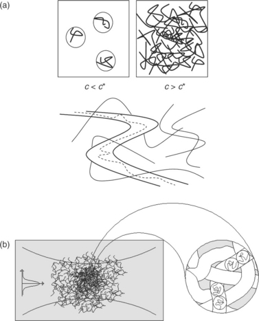
7.2 (a) Schematic of dilute (upper left) and semidilute (upper right) solution regimes. (Below) Each polymer is constrained to move within a topological tube due to the presence of the confining surrounding polymers. Within this tube the polymer performs a snake-like reptation motion in the polymer melt. (b) Conceptual view of polymer mesh in the focal point of laser (left) and ‘blobs’ forming entangled ‘tube’ in solution (right).
In general, the Edwards tube concept of macromolecular motion is considered to be a rather difficult many-body problem. Pierre-Gilles de Gennes succeeded in reducing this many-body problem to the motion of a single chain as it is confined in a tube formed by the surrounding chains (Fig. 7.2b). The simplest tube model was proposed by de Gennes (1971) for the motion of linear entangled polymers, called the reptation model. That model was introduced to explain the dependence of the mobility of a macromolecule on its length. According to the model, the polymer chains are reptating through tubes whose formation and shape is dictated by the neighboring chains and their entanglement points.
7.3.2 Estimations of radiation forces
In order to ensure that radiation forces are capable of organizing the polymer chains to create structures, a feasibility study is necessary. Let us consider a semidilute polyisoprene solution of molecular weight Mw = 1.500 kg/mol in n-heptane at 40%wt which exhibits concentration of c = 0.3 g/cm3 which is much greater than the overlap concentration c* ~ 0.008 g/cm3, indicating a semidilute solution at a high degree of entanglement. In that case, the refractive index of the pure polymer (npol = 1.52) is higher than the refractive index of the solvent (nsolv = 1.388). As a laser beam of relatively large numerical aperture and intensity is incident on a polymer solution, two types of forces act concurrently, namely the scattering and the gradient force, defined previously, giving the resultant optical force that interacts with the semidilute polymer solution. Given Me the length of macromolecule between adjacent entanglements, a number of  of about 259 tangles per polymer chain are expected with
  monomers per entanglement. We may thus define here a parameter describing the chain segment between adjacent nodes as a ‘suprablob’. The suprablob can be heuristically considered as a spherical nanoparticle composed of a chain section between tangles. It is surrounded by solvent and has a density and refractive index which ranges in between the values of melt and solution average. In analogy to the blob parameter, a diameter of D ~ (2Ne/c)1/3 ~ 7 nm may be estimated for the given concentration (Fig. 7.2b). The resultant polarizability is thus estimated in the range of α = 6 × 10−37 Fm2 and thus, the gradient force Fgr can be estimated at about Fgr ~ 2–3 × 10⁻¹⁸ N on each suprablob particle. We note, though, that due to the strong connectivity and high degree of entanglement, the forces are summed as depicted in Fig. 7.3, giving a total force acting on the polymer mesh. This total gradient force far exceeds the Brownian motion force (FB ~ 10−29 N), and thus leads to the evolution of the phenomenon.

As previously mentioned, the gradient forces compel the particles to reconfigure their spatial distribution leading to an organized spatial variation of a refractive index in the solution. This effect is greatly assisted here by the connectivity. By these means, the first condensate is created at the focal point of the objective. Due to its transparency and slightly different refractive index from the surrounding medium it produces a Mie scattering. Several Mie scattering configurations are simulated in Fig. 7.4a to strengthen this perspective. It becomes apparent that since the initial stages of formation a strong forward and backward field is produced which enhances further the applied forces and leads to attraction of soft matter. In weak focusing conditions an array of microspherical regions, condensates, is formed in liquid phase since the induced microlens refocuses the incoming light in a neighboring region as depicted in Fig. 7.4b and observed experimentally (Sigel et al., 2002). Each of the induced microlenses acts to refocus the incident field at consecutive positions along the incident beam propagation, resulting in the simultaneous buildup of the array. Considering the gradient forces, the members of this array should be located at local minima of the trapping potential, or otherwise at the foci of the formed beam. Upon prolonged exposure this may result in the gradual buildup of the fiber-like microstructures as demonstrated in the next section. Furthermore, under strong focusing conditions the Mie scattered field and the consequent high field produces strong condensation at the focal point and a fast attraction of matter to create microstructures as schematically shown in Fig. 7.4c and presented in the next section.

7.4a (a) Simulation of Mie scattering (by uniform spherical polymeric condensates). Light intensity {I(r)} distribution of field scattered by spheres of various radii. The incident plane wave has I = 1, is right circularly polarized at wavelength λ = 671 nm and propagates from the left to right toward the +z-direction. The pseudochrome gray scale is absolute with respect to unity. Simulation by electromagnetic Mie scattering methods.
7.4 Organization and microfabrication by radiation forces: an emerging technology
The creation of polymer condensates and micro-/nanostructures implemented in various forms is discussed here. It includes formations in bulk solution, thin films, free space and finally the drawing of fibers, each requiring experimental procedures resulting in structures of different shapes and characteristics.
7.4.1 Material densification in bulk solutions
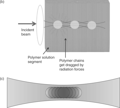
A focused Gaussian beam emitting in the red is propagating in a semidilute polymer solution as depicted in the experimental configuration of Fig. 7.5. In the experimental arrangement, the cuvette containing the semidilute polymer solution is placed on a translation stage to facilitate positioning. The process is monitored in real time by a CCD camera and the profile of the laser beam is monitored on a screen. The laser beam is allowed to pass through the polymer solution for a time period of a few seconds (Fig. 7.6a) and recorded by the CCD camera. The actual beam profile observed on the screen is Gaussian with a smooth intensity distribution shown in Fig. 7.7a. After a short period, the creation of the condensate in the solution scatters the transmitted light as observed by a gradual change in the beam profile depicted in Fig. 7.7b, 7.7c and 7.7d. The CCD camera records an increase of intensity of the transversely scattered beam propagating in the condensate, as recorded in Fig. 7.6b, indicating lossy waveguiding through the formatted fiber string. This waveguiding phenomenon is induced due to the radial refractive index gradient in the newly formed fiber, owing to the refractive index difference between the pure polymer solute (n = 1.51 for PI) and the solvent (n = 1.37 for n-hexane). In effect, due to radiation forces, the solute polymer chains are dragged along the beam axis, forming a string-like structure along this axis. Concurrently the solvent is forced osmotically to move away and the solvent is replaced by the polymer chains along the beam axis.

7.5 Experimental setup for structure creation in cuvette. The beam profile is projected onto a screen.
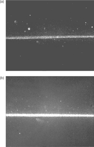
7.6 (a) The laser beam passes through the polymer solution; (b) the laser beam is waveguided by the formatted structure.

7.7 (a) The laser beam profile upon laser illumination initiation, (b), (c), (d) gradual change of beam profile due to scattering from the created structure.
To elucidate the process, let us consider the phenomenon through a more extensive perspective for condensate microstructure creation by referring back to the schematic of Figs. 7.4b and 7.4c. The laser beam of some tens of mW power is transmitted through a positive lens and is focused weakly (e.g. by a f = 150–200 cm lens) in the polymer solution producing some kW/cm2 intensities at focus. The laser radiation and gradient forces localized in the focus point of the lens tend to drag the polymer chains formerly dispersed in the solution in a random manner to form a polymer microsphere condensate. The latter acts in turn as a second focusing element that forms a third one, thus consecutively creating a series of microspherical condensates (Fig. 7.4b). As discussed above this array formation is a simultaneous process. In effect, as a consequence of the accumulation of the microspheres, a string-like almost macroscopic structure may be formed upon prolonged exposure, or a direct formation of a fiber string is realized under suitable conditions. The phenomenon is self-terminated, when no further polymer chains can join the micro-string, due to inability of radiation forces to drag efficiently more matter. Macroscopically, the termination of the process is signaled on the screen where the beam profile becomes stationary, but on the contrary, it appears frozen after a period of time when steady state of formation is reached.
The quality of the structures can be further improved by controlling several parameters, such as the laser intensity, by the objective focal length, the exposure time, the solution characteristics (concentration, viscosity, etc.) and others.
7.4.2 Microstructure creation in thin films and freestanding structures
Radiation forces can be employed as a manipulation tool for polymer thin films. In the context of the aforementioned scheme, a polymer solution is deposited to form a thin film. In this form the material exhibits a smaller degree of freedom as compared to the bulk solution, owing to the smaller total volume of material available, the strong surface interactions and contact with the environment. The polymer chains are thus not fully free to move under the gradient force, but forces act to manipulate the surface by dragging the polymer and counteracting surface tension thus leading to the formation of elongated microstructures on the thin film surface. The created structures remain localized in a fraction of volume and remain a function of the force field imposed.
Experimentally the deposition of the polymer solution on the glass substrates was facilitated using the doctor blade deposition method. The thickness of the polymer film was controlled by micropositioning the blade and parallel movement in order to produce a uniform spread. The distance between the razor and the substrate is controlling the thickness of the films. The thickness of the samples was in the order of several microns. In a complementary way, thin films may be deposited via spin coating where, depending on the viscosity, the solution needs to be in a rather fluid form.
A typical setup used to controllably organize the polymer material and create solid structures by manipulating the surface of thin films deposited on glass substrates is shown in Fig. 7.8. It consists of a cw laser diode source emitting in the visible, in our case at 671 nm, a microscope objective lens, a series of beam aligning mirrors and a translation stage for micromotion control. A Peltier heater device is placed under the glass substrate for the fast vaporization of the solvent and the concurrent solidification of the solute. A center hole-Peltier module is preferable, due to the fact that the laser beam is allowed to pass through the hole and interact with the thin film, while concurrently the glass substrate is heated in a sought temperature, controlled by a power supply. The writing process is real time monitored via a CCD camera system attached next to the film.

Surface patterning by radiation forces
By applying moderate laser power in the order of some tens mW, corresponding to a few ~ MW/cm2 at focus, and by a short illumination time duration ranging from a few seconds up to some minutes, a semi-transparent microstructure is created at the focusing point of the objective lens, due to optical radiation forces. For a post-illumination treatment the sample is left on the Peltier device for about 1 h at 60°C and then carefully stored. Exposure duration is of the order of some tens of seconds depending on the concentration and viscosity of the polymer solution, for given laser parameters.
In an attempt to investigate the effect of the beam on the surface morphology two identical films comprising PI-PVP-Au nanoparticles were examined by AFM, one of them being irradiated with a focused laser beam. The results are shown in Fig. 7.9. The effect of the laser beam in the irradiated film becomes apparent, creating a visible recess in the surface of the film. Similar structures were further observed with both profilometer (Tencor Alpha-Step 500IQ) and Atomic Force Microscope as depicted in Fig. 7.10.

7.9 AFM image of a smooth (up) film surface and rough (down) film surface, indicative of a structure formation on it.
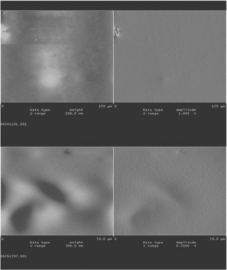
7.10 (Up) and (down): AFM images of film surface showing bulges on top, indicative of structure formation on it.
In order to examine the effect of focusing on the resultant structures, a number of objective lenses exhibiting different magnification powers (10× and 20×) were used. The resultant structures were found to be highly dependent on the magnification of the lenses, with the structure size being inversely proportional to the magnification power of the lens owing to the focusing strength, thus confirming the theoretical expectations. In particular, in the case of 20× objective lens, it was noticed that only one sphere of large diameter was created, albeit the relevantly high writing duration and full power of laser irradiation. Given the depth of focus, Δf:
where:  , for both 10× (0.25 NA) and 20× (0.4 NA) objectives we have Δf ~ 5 and 2, respectively. These numbers corroborate the creation of rod-like structures by longer depth of focus imaging, whereas shorter depth of focus produces spherical micropatterns.
Experimentally it has been observed that integrated exposure is a main parameter in structure fabrication. In our attempt to investigate the effect of laser beam exposure in the creation of patterns, the power of the laser beam was changed, by using an optical attenuator, from 150 to 70 mW, as measured with a power meter (Newport model 2832-C Dual Channel). It was found that in order to achieve a structure of the same dimensions, almost double writing time was needed, that is by using a 10× objective in both cases, the exposure time was about 10–15 s at full power of ~ 150 mW, and 30–40 s for the lowest attenuated beam of ~ 70 mW. Thus, the resulting structure was created at longer writing times, indicating the inverse proportionality of the two parameters. The dependence of the structure length on exposure time for given power is shown in Fig. 7.11 and appears almost linear. A typical created structure is about 0.4 mm in length and about 10 μm in diameter.

Application of holographic optics for surface microstructuring
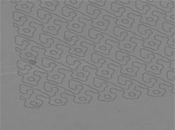
Given the phenomenon of structure creation in liquid-phase solution as well as in thin films, someone could try to create multiple structures concurrently by using optical techniques such as holographic masks. The holographic masks were designed by using special software for CGHs holographic laser beam splitters in particular. The fan-out of the masks was formerly designed in CAD software. Then, it was inserted in software for calculation of the sought holographic mask. The calculated mask is again inserted in CAD software for replication in order to increase the overall size without reducing the resolution. The final mask design is transferred onto glass substrate with metal oxides, by using the reactive ion etching (RIE) technique. Several masks were manufactured exhibiting different fan-out configurations as shown in Fig. 7.12.

The holographic masks are designed on the computer using special software for computer generated holograms (CGHs) and a typical micrograph of such a holographic mask produced on oxide coated silica substrate is presented in Fig 7.13.
Surface microstructures by fan-out irradiation were created in thin films of PB (polybutadiene) under similar writing procedures. The experimental arrangement of Fig. 7.14a was used and the laser beam was properly manipulated before entering the film by inserting the holographic mask. Fan-out patterns were transferred onto the film and imaged by a microscope as shown in Fig. 7.14b, where the features correspond to surface modifications induced by transferring simultaneously all the fan-out topology. The resulting structures have also been characterized by SEM and the diameter of spots was found to be in the range of 50–60 μm.

Creation of freestanding structures
Interesting results can be obtained by modifying the orientation of the thin film with reference to the beam normal. Parallel, perpendicular and slightly tilted configurations have been used to investigate the dependence of angle of incidence to the geometrical characteristics and uniformity of the structures. In a vertical direction, normal to the film, with the deposited material being under the glass surface, tiny columns of material of the film appear on the substrate surface, aided minimally by gravity forces. Typical three-dimensional cylinder rod-like microstructure formed on planar parent substrates are shown in Fig. 7.15a and 7.15b, with structure diameter of the order of 5–10 μm. Upon illumination, the structures exhibit remarkable waveguiding properties, though lossy due to scattering effects. As outlined above, such properties are attributed to the refractive index gradient owing to the difference between the polymer solute (nPI = 1.51) and the solvent n-heptane (nS = 1.39). In the case of 1,4-polybutadiene the refractive index variation applies as nPB = 1.51 and ndecane = 1.41.

7.15 Scanning electron micrographs of (a) a string-like microstructure, (b) the edge of the structure.
The length of the structures was found to be in the range of 20–25 μm, the diameter about 3 μm, while the height above the substrate surface was about 300 nm. It should be mentioned at this point that the created structures cannot be extracted from the film due to the strong adhesion forces evolved in the material.
As previously mentioned, the tiny columns can be likened to rods. The rods could not be noticed by observation through an optical microscope due to the orientation of the structures and only the edges were visible. They were short and rather thick in order to be self-standing, static and self-supported. Once the structures get quite long (in the order of mm), they appear to be curved due to gravity and the viscoelastic nature of the material.
The writing/creation of microstructures can be accomplished in almost any form of entangled polymer solution. The aforementioned setup was used for the writing of a structure in a polymer droplet that had just been ejected from a syringe tip, in free space. The resulting structure was then observed through a microscope, as shown in Fig. 7.16.

7.4.3 Plasmonic and fluorescent quantum dots hybrid structures
In a complementary effort, the polymer solution acts as a matrix element where several dopants can be added. Metal Au nanoparticles can be successfully added in the polymer matrix by following the procedures outlined in the annex. The structures to be created using this solution exhibit remarkable plasmonic characteristics. Furthermore, CdS quantum dots were added in the polymer solution in micellar form. The final solution has a yellowish appearance due to quantum dots. The solution was then deposited onto a glass substrate following the same procedure for microfiber creation in the thin film, and the created microstructures were observed under the microscope. In Fig. 7.17a and 7.17b, two created structures are shown via optical microscope in Fig. 7.17a and the same structures are examined using a fluorescence microscope in Fig. 7.17b. The intense contrast between the polymer thin films and the created structures is apparent due to the fact that the quantum dots were dragged and accumulated at high concentrations during the formation process, being trapped in the net of entangled polymer chains under the exertion of optical forces.

7.4.4 Fiber drawing by laser radiation forces
The experimental setup was further changed in order to examine the feasibility of structure creation in open space. The setup consisted of a laser source, an objective lens and a syringe carrying the polymer solution. The lens used was 10×, the laser operated at full power (150 mW) and the writing process was monitored in real time using a CCD camera. The laser beam was focused in a microdroplet formed at the syringe tip as shown in Fig. 7.18a. Radiation forces are applied and drag a polymer fiber by pulling and solidifying the entangled polymer in free space. This process is self-sustained as feeding comes naturally through the syringe. The phenomenon is thus self-conserved resulting in the creation of a flocculent and fully elastic PI fiber rubbery structure. The ring-like appearance shown in Fig. 7.18b is due to self-winding. The total duration of the process is about 10–15 min. It should also be noted here that the whole process is driven by radiation forces and no further operation is needed to assist the fiber drawing process.
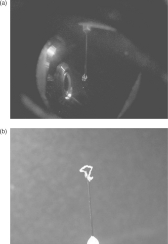
7.18 (a) Real-time image of the fiber-drawing process. (b) Ring-like structure formation at the edge of a syringe needle.
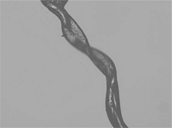
The structures created by using that method develop strong electrostatic forces. By approaching a metal tip, the polymer string is strongly affected, moving toward the tip. In addition, the string is highly elastic acting as a spring; the typical structure shown in Fig. 7.19 exhibits a rubbery mechanical response, as expected for the PI material. A close-up of helical structures formed is shown in the optical microscope image of Fig. 7.20.

7.4.5 Hybrid structure formation
Hybrid materials have been synthesized as described in the appendix and used in the context of this work. The above microstructure formation process has also been achieved using PI enriched with CdS quantum dots. A typical TEM image of a CdS encapsulated micelle is shown in Fig. 7.21. Both freestanding structure formation and fiber drawing operations have been performed. The structures produced are found to be highly fluorescent as compared to the parent material owing to the strong densification and trapping of quantum dots. In the open space fiber drawing mode, very long strings (~ 10 cm) have been created. The fluorescent objects formed were observed under the fluorescent microscope and spectrally analyzed. A typical fluorescent emission spectrum recorded is shown in Fig. 7.22, with the peak at λfluor ~ 470 nm indicating a maximum CdS quantum dot size of ~ 4 nm. In a similar operation, the plasmonic behavior of Au enriched material has been verified with typical absorption curves depicted in Fig. 7.23. A typical TEM image of the Au nanoparticles encapsulated micelles is shown in Fig. 7.24. In both cases identical responses with respect to the parent solutions depicted in dotted lines in Figs. 7.22 and 7.23 have been observed with minimal shifts indicating the created denser ambient matrix environment for the nanoparticles and quantum dots. No detrimental effects such as metallization and fluorescence quenching have been observed, verifying that the formation process is dielectrically shielded ensuring absence of aggregation in the final solidified nanocomposites.


7.22 Fluorescent emission curve of a freestanding polymer structure containing CdS quantum dots. The dotted curve is the spectrum of the polymer solution.


7.4.6 Process reversibility and intact materials nature
Significant efforts were devoted to establishing a picture regarding non-reversible chemical processes which may take place during formation of the nanostructures, and may compromise reversibility of the formation process. One concern is the chemical stability of polydienes under prolonged and intense irradiation with a laser beam, due to the presence of C=C bonds. Careful NMR and SEC experiments on the polymeric materials isolated after sample irradiation indicated no detectable changes in their chemical structure (i.e. absence of oxidation), as well as the absence of cross-linking or chain scission. The absence of appreciable cross-linking was also verified by dynamic light scattering measurements in solutions of the irradiated material in THF. Reversibility testing of the created structures was performed. Solvent was added to a 3D structure and after stirring for some minutes, the structure disappeared being transformed to the solution previously used. Such findings verifying reversibility in liquid condensates have also been reported by Sigel et al. (2002).
7.5 Conclusions and future prospects
The composition of scattering and gradient radiation forces is now offering important tools for the manipulation of inorganic and biological matter by means of particle trapping using optical tweezers and structure actuation. Beyond these applications, the concept of light-induced forces exerted in soft matter at the mesoscale opens up new horizons by allowing efficient density manipulation and the formation of solid objects. Microstructure creation is implemented solely by the above optical means in semidilute, entangled polymer solutions with remarkable results. Pointing to an emerging microfabrication technology, especially suitable for photonics applications, we demonstrated and discussed in this chapter several forms of structures in planar and three-dimensional freestanding micro-objects, in addition to a unique polymer fiber drawing operation, by the sole use of radiation forces.
The observed intriguing phenomena are currently under further study and may be illustrated in terms of a synergy of radiation forces, chain entanglement and optical field structuring and waveguiding, as discussed in this work. The topic offers new scope for fundamental investigations in polymer science and photonics. Emerging concepts on materials microstructuring in three dimensions would take advantage of the chemically inert nature of the process to yield a rich palette of microfabrication tools. These will offer compatibility with both inorganic devices and biological material, leading the way to hybridization and novel lab-on-chip schemes. The ability to tailor surfaces in the nanoscale with reversibility may also offer new tools in optical memory and related applications, and prompt hybrid and unified approaches in photonics, information and biomedical technologies.
7.6 Acknowledgments
This research has been co-financed by the European Union (European Social Fund, ESF) and Greek national funds through the Operational Program ‘Education and Lifelong Learning’ of the National Strategic Reference Framework (NSRF) — Research Funding Program: Heracleitus II. Investing in knowledge society through the European Social Fund. The authors would like to acknowledge the contributions of Prof. Ioannis Koutselas and Dr Vaggelis Karoutsos in the analysis of results. Useful discussions with Prof Yanopappas, Dr D. Alexandropoulos and M. Vasileiadis are also gratefully acknowledged.
7.7 References
Anyfantakis, M., Loppinet, B., Fytas, G., Pispas, S. Optical spatial solitons and modulation instabilities in transparent entangled polymer solutions. Optics Letters. 2008; 23:2839–2841.
Anyfantakis, M., Loppinet, B., Fytas, G., Mantzaridis, C., Pispas, S., Butt, H.J. Experimental investigation of long time irradiation in polydienes solutions: Reversibility and instabilities. Journal of Optics. 2010; 12:124013.
Ashkin, A. Acceleration and trapping of particles by radiation forces. Physics Review Letters. 1970; 24:156–159.
Ashkin, A. Trapping of atoms by resonance radiation pressure. Physics Review Letters. 1978; 40:729–732.
Ashkin, A. Forces of a single-beam gradient laser trap on a dielectric sphere in the ray optics regime. Biophysical Journal. 1992; 61:569–582.
Ashkin, A., Dziedzic, M., Bjorkholm, J.E., Chu, S. Observation of a single-beam gradient force optical trap for dielectric particles. Optic Letters. 1986; 11:288–290.
Cizmar, T., Davila Romero, L.C., Dholakia, K., Andrews, D.L. Multiple optical trapping and binding: New routes to self-assembly. Journal of Physics B: Atomic, Molecular and Optical Physics. 2010; 43:102001.
de Gennes, P.G. Reptation of a polymer chain in the presence of fixed obstacles. Journal of Chemical Physics. 1971; 55:572–579.
Dholakia, K., Zemanek, P. Gripped by light: Optical binding. Reviews of Modern Physics. 2010; 82:1767–1791.
Dienerowitz, M., Mazilu, M., Dholakia, K. Optical manipulation of nanoparticles: A review. Journal of Nanophotonics. 2008; 2:021875.
Draine, B.T. The discrete-dipole approximation and its application to interstellar graphite grains. The Astrophysical Journal. 1988; 333:848–872.
Gatsouli, K., Pispas, S., Kamitsos, E.I. Development and optical properties of cadmium sulfide and cadmium selenide nanoparticles in amphiphilic block copolymer micellar-like aggregates. Journal of Physical Chemistry C. 2007; 111:15201–15209.
Greene, W.M., Spjut, R.E., Bar-Ziv, E., Sarofim, A.F., Longwell, J.P. Photophoresis of irradiated spheres: Absorption centers. Journal of the Optical Society of America B. 1985; 2:998–1004.
Hadjichrisitidis, N., Iatrou, H., Pispas, S., Pitsikalis, M. Anionic polymerization: High vacuum techniques. Journal of Polymer Science Part A: Polymer Chemistry. 2000; 38:3211–3234.
Harada, Y., Asakura, T. Radiation forces on a dielectric sphere in the Rayleigh scattering regime. Optics Communications. 1996; 124:529–541.
Jonas, A., Zemanek, P. Light at work: The use of optical forces for particle manipulation, sorting, and analysis. Electrophoresis. 2008; 29:4813–4851.
Loppinet, B., Somma, E., Vainos, N., Fytas, G. Reversible holographic grating formation in polymer solutions. Journal of the American Chemical Society. 2005; 127:9678–9679.
Maxwell, J.C.A treatise on electricity and magnetism. Oxford: Clarendon Press, 1873.
Meristoudi, A., Pispas, S., Vainos, N. Self-assembly in solutions of block and random copolymers during metal nanoparticle formation. Journal of Polymer Science Part B: Polymer Physics. 2008; 46:1515–1524.
Metzger, N.K., Wright, E.M., Dholakia, K. Theory and simulation of the bistable behavior of optically bound particles in the Mie size regime. New Journal of Physics. 2006; 8:139.
Neuman, K.C., Block, S.M. Optical trapping. Review of Scientific Instruments. 2004; 75:2787–2809.
Nieminen, T.A., Knoner, G., Heckenberg, N.R., Rubinsztein-Dunlop, H. Physics of optical tweezers. Methods in Cell Biology. 2007; 82:207–236.
Sigel, R., Fytas, G., Vainos, N., Pispas, S., Hadjichrisitidis, N. Pattern formation in homogeneous polymer solutions induced by a continuous-wave visible laser. Science. 2002; 297:67–70.
Stevenson, D.J., Gunn-Moore, F., Dholakia, K. Light forces the pace: Optical manipulation for biophotonics. Journal of Biomedical Optics. 2010; 15:041503.
Uhrig, D., Mays, J.W. Experimental techniques in high-vacuum anionic polymerization. Journal of Polymer Science Part A: Polymer Chemistry. 2005; 43:6179–6222.
7.8 Appendix
7.8.1 Synthesis and characterization of polymer materials and hybrids
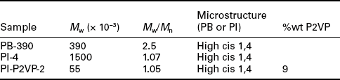
High cis 1,4 polybutadiene (PB) sample has been utilized, having a branched molecular architecture. High molecular weight polyisoprene (PI) homopolymer was prepared in-house by the use of anionic polymerization high vacuum techniques (Hadjichrisitidis et al., 2000; Uhrig and Mays, 2005) utilizing home-made glass reactors and break seal techniques. s-BuLi was the initiator used in the non-polar solvent benzene. Polymerization reactions were carried out at room temperature. Under these conditions PI chains of low molecular weight distribution with controlled molecular weights and having high 1,4 microstructure are obtained, as evidenced by size exclusion chromatography determinations and 1H-NMR spectroscopy measurements. The final PI homopolymer was isolated by precipitation in stabilized methanol and dried under vacuum for several days at room temperature. The polyisoprene-b-poly(2-vinyl pyridine) (PI-P2VP) block copolymer also employed as the polymeric functional material in these studies was obtained by an anionic polymerization scheme involving two steps. Isoprene monomer was polymerized first in benzene at room temperature, using s-BuLi as initiator, according to previously described procedures. The living poly(isoprenyl lithium) solution was isolated in a glass ampoule, equipped with a break seal, and was subsequently utilized as the macroinitiator for the polymerization of 2-vinylpyridine. Polymerization of the second monomer was carried out in THF at −78°C. The small amount of benzene present from the preparation of the PI macroinitiator does not perturb the formation of the poly(2-vinyl pyridine block) (P2VP). After formation of the P2VP block, deactivation of the living chains was achieved by degassed methanol. The copolymer solution in THF was concentrated in a rotor evaporator (by distilling about 2/3 of the solvent) since direct precipitation of the copolymer from the THF-rich solution is not quantitative. The pure PI-P2VP diblock copolymer was then isolated in solid form by precipitation in stabilized cold methanol and dried in a vacuum oven at room temperature for several days.
Polymer samples were characterized in terms of molecular weight and molecular weight distribution by size exclusion chromatography (SEC), as well as in terms of PI microstructure and copolymer composition by 1H-NMR spectroscopy. The detailed molecular characteristics of the samples utilized are shown in Table 7.1. No alteration of their chemistry has been observed by the formation operation.
7.8.2 Preparation of PI-P2VP micelles containing Au or CdS nanoparticles
PI-P2VP micelles were prepared in n-heptane which is a selective solvent for the PI block. The solid polymer was directly dissolved in the solvent in a stopper vial in order to give a copolymer concentration CPI-P2VP = 1% w/v. The solution was subsequently heated at 60°C for 2 h in order to facilitate complete dissolution of the copolymer and equilibration of the micelles. In this solvent the copolymer forms spherical micelles with P2VP cores and PI coronas. This is evidenced even by the naked eye due to the bluish tint developed in the solution. Quantitative dynamic light scattering measurements after 24 h of solution preparation gave the mean hydrodynamic radius of the micelles (Rh = 33.6 nm).
The PI-P2VP micelles were subsequently utilized as nanoreactors for the synthesis of Au and CdS nanoparticles. In the case of Au metal nanoparticle formation, auric acid (as ethanolic solution) was introduced in the PI-P2VP micellar solution in the predetermined stoichiometric amount to the pyridine units (N:Au = 4:1). This high N:Au ratio facilitates quantitative complexation of the gold ions with the nitrogen atoms of the pyridine rings of the copolymer. Complexation of the pyridine units of the P2VP block with the gold ions takes place in the micellar cores which act as nanoreactors for metal nanoparticle nucleation and growth. After allowing for equilibration for 24 h, gold ions were reduced to gold by the use of hydrazine solution in ethanol (hydrazine:Au = 4:1). The nanoconfinement of the micellar cores led to the production of gold metal nanoparticles, as evidenced by UV-vis spectroscopy measurements (Meristoudi et al., 2008). Adsorption maximum for the surface plasmon resonance peak of the produced gold nanoparticles was observed at ca. 540 nm.
A similar preparation protocol was also followed in the second case. Cd2+ ions were loaded in the PI-P2VP micellar cores in the form of cadmium acetate (N:Cd2+ = 4:1). The mixed solution was allowed under stirring for 24 h. During this period cadmium acetate was completely dissolved, presumably within the micellar cores, due to the chemical affinity of the polar pyridine groups for the Cd2+ ions. In the next step, thioacetamide was introduced into the solution of loaded block copolymer micelles. Thioacetamide was utilized as the source for sulfur, through its decomposition at 80°C (S/Cd ratio was kept at 2). The formation of CdS nanoparticles in PI-P2VP micelles was confirmed by UV-vis and fluorescence spectroscopy (Gatsouli et al., 2007).
Inorganic nanoparticle loaded block copolymer micelles were mixed with solutions of PB and PI homopolymers in n-hexane in order to produce hybrid non-covalent interacting homopolymer/micelles mixtures. The similar chemical composition of the micellar corona with the matrix homopolymer enhances such interactions and facilitates decoration of fibrilar polydiene structures, formed upon subsequent exposure of solutions to laser radiation. In this way hybrid nanostructures are produced solely by the laser action. Fluorescent hybrid CdS/PI-P2VP micelles may act also as markers/probes for direct visualization of homopolymer chain ordering.