
Chapter 13
Drawing Shapes
In This Chapter
![]() Creating basic shapes such as lines, rectangles, circles, and ellipses
Creating basic shapes such as lines, rectangles, circles, and ellipses
![]() Creating shapes you can see through
Creating shapes you can see through
![]() Creating gradient fills
Creating gradient fills
![]() Rotating, translating, and scaling shapes
Rotating, translating, and scaling shapes
![]() Drawing some text
Drawing some text
![]() Combining shapes with union, intersect, and subtract operations
Combining shapes with union, intersect, and subtract operations
Were you one of those kids who, way back in school, passed away the boring hours of algebra class by doodling in the margins of the book? If so, you’re in luck. Now that you’re a grownup and you’re mastering JavaFX programming, you don’t have to doodle in the book. Instead, you can write programs that doodle onscreen.
This chapter is a brief introduction to the fascinating world of drawing in JavaFX. Specifically, you figure out how to draw two-dimensional objects such as lines, arcs, rectangles, ellipses, and so on. You can set the style used to draw the shape’s outline, and you can fill the shape with a solid color, a gradient fill, or text that’s created from an image. You can make your shapes solid or transparent, and you can rotate, clip, skew, and do all sorts of other unspeakable things to them.
Introducing the Shape Class
So far in this book, you’ve read about two types of nodes you can add to a scene graph: controls, which inherit the Control class, and layout panes, which inherit the Pane class. In this section, you read about how to work with a third type of node: shapes, which (as you might guess) inherit the Shape class. Table 13-1 lists some of the most commonly used methods of the Shape class.
Table 13-1 The Shape Class
|
Method |
Description |
|
void setFill(Paint value) |
Sets the fill color. |
|
void setSmooth(boolean value) |
If true, anti-aliasing is used to draw the shape more precisely. |
|
void setStroke(Paint value) |
Sets the color of the stroke used to draw the shape’s outline. |
|
void setStrokeWidth(double value) |
Sets the width of the stroke used to draw the shape’s outline. |
|
void setStrokeType(StrokeType value) |
Sets the position of the stroke relative to the actual outline of the shape. Allowable values are StrokeType.CENTERED, StrokeType.INSIDE, and StrokeType.OUTSIDE. |
|
void setStrokeLineJoin(StrokeLineJoin value) |
Sets the method used to draw corners. Allowable values are StrokeLineJoin.MITER, StrokeType.BEVEL, and StrokeType.ROUND. |
|
void setStrokeEndCap(StrokeEndCap value) |
Sets the method used to draw the ends of the stroke line. Allowable values are StrokeLineCap.BUTT, StrokeLineCap.ROUND, and StrokeLineCap.SQUARE. |
|
static Shape intersect(Shape shape1, Shape shape2) |
Returns a new shape that consists only of those parts of shape1 and shape2 that overlap. |
|
static Shape subtract(Shape shape1, Shape shape2) |
Returns a new shape that is formed by subtracting the shape2 from shape1. |
|
static Shape union(Shape shape1, Shape shape2) |
Returns a new shape that is formed by adding shape1 to shape2. |
There are a total of 12 shapes that inherit the Shape class: Arc, Circle, CubicCurve, Ellipse, Line, Path, Polygon, Polyline, QuadCurve, Rectangle, SVGPath, and Text. Table 13-2 shows a basic constructor for each of these classes, and Figure 13-1 shows a scene with a sample of several of them. The code that created this figure is shown in Listing 13-1, later in the chapter.
Table 13-2 Twelve Kinds of Shape Classes
|
Class Constructor |
Description |
|
Arc(double centerX, |
Creates an arc, which is a segment of an ellipse defined by the first four parameters. startAngle is the angle in degrees of the starting point of the arc, and length is the angular extent of the arc in degrees. The Arc class also includes a method named setType that lets you set the type of the arc. Allowable values are ArcType.CHORD, ArcType.OPEN, and ArcType.ROUND. |
|
Circle(double centerX, |
Creates a circle with the specified center point and radius. |
|
CubicCurve(double startX, |
Creates a curve with the specified start and end points and the specified control points. |
|
Ellipse(double centerX, |
Creates an ellipse. centerX and centerY specify the center point of the ellipse. radiusX specifies the horizontal radius of the ellipse, and radiusY species the vertical radius. |
|
Line(double startX, |
Creates a line with the specified start and end points. |
|
Path(PathElement... elements) |
Creates a path with the specified path elements. |
|
Polygon (Double... points) |
Creates a polygon with the specified x, y points as its vertices. |
|
Polyline (Double... points) |
Creates a polyline with the specified x, y points as its segments. |
|
QuadCurve(double startX, |
Creates a quadratic curve with the specified start and end points and the specified control points. |
|
Rectangle(double x, |
Creates a rectangle. x and y specify the top-left corner of the rectangle. |
|
SVGPath() |
Creates a Scalable Vector Graphics (SVG) path. |
|
Text(double x, |
Creates a text shape with the specified text at the specified x and y coordinates. |
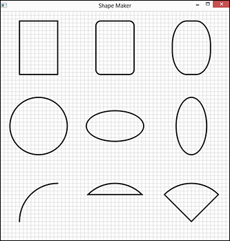
Figure 13-1: A bunch of shapes.
Creating lines
The most basic type of shape is a line, created with the Line class. To create a line, you specify the x and y coordinates of the start and end of the line, as in this example:
Line line1 = new Line(0, 0, 100, 200);
This code creates a line that goes from (0,0) to (100, 200).
The grid lines in Figure 13-1 were drawn by line shapes inside a for loop, like this:
for (int i = 0; i <600; i+=10)
{
Line line1 = new Line(i, 0, i, 600);
line1.setStroke(Color.LIGHTGRAY);
Line line2 = new Line(0, i, 600, i);
line2.setStroke(Color.LIGHTGRAY);
group1.getChildren().addAll(line1, line2);
}
The for loop iterates a variable i from 0 to 600 in increments of 10. On each iteration of the loop, two lines are created: a vertical line that uses the variable i as its x-axis and a horizontal line that uses the variable i as its y-axis. The stroke color for each line is set to light gray, and the lines are then added to a Group object named group1.
Creating rectangles
A rectangle requires an (x, y) starting point, a width, and a height. Here’s the code that creates the first rectangle shown in Figure 13-1 earlier in this chapter:
Rectangle r1 = new Rectangle(50,25,100,140);
r1.setStroke(Color.BLACK);
r1.setFill(null);
r1.setStrokeWidth(3);
Here the rectangle starts at (50, 25). Its width is 100, and its height is 140. Notice that the fill color is set to null so that the rectangle will be transparent.
You can create a rectangle with rounded corners by calling the setArcWidth and setArcheight methods. Here’s the rounded rectangle in the middle of the first row of shapes shown in Figure 13-1:
Rectangle r2 = new Rectangle(250,25,100,140);
r2.setStroke(Color.BLACK);
r2.setFill(null);
r2.setStrokeWidth(3);
r2.setArcWidth(25);
r2.setArcHeight(25);
Here, the corners are rounded with an arc whose height and width are both 25.
You can create some interesting shapes by using unequal values for the arc’s width and height. For the third shape in the first row of Figure 13-1, arc width is set to 75 and the height to 125:
Rectangle r3 = new Rectangle(450,25,100,140);
r3.setStroke(Color.BLACK);
r3.setFill(null);
r3.setStrokeWidth(3);
r3.setArcWidth(75);
r3.setArcHeight(125);
Creating circles and ellipses
To create a circle, you use the Circle class, specifying the x- and y-coordinates of the center of the circle and the radius. Here’s the code that creates the circle in Figure 13-1:
Circle c1 = new Circle(100, 300, 75);
c1.setStroke(Color.BLACK);
c1.setFill(null);
c1.setStrokeWidth(3);
An ellipse is similar to a circle, but has two radii: one in the x-axis, the other in the y-axis. You specify both radii in the constructor. Here’s the code that creates the first ellipse in Figure 13-1:
Ellipse e1 = new Ellipse(300, 300, 75, 40);
e1.setStroke(Color.BLACK);
e1.setFill(null);
e1.setStrokeWidth(3);
The second ellipse is similar, but the x- and y-radii are reversed:
Ellipse e2 = new Ellipse(300, 300, 40, 75);
Creating arcs
Another useful type of shape is an arc, which is a segment of an ellipse. To create an arc, you supply the parameters for the ellipse and then you supply the angle at which the arc begins: 0 is due east (3:00 on a clock face). Finally, you supply the length, which represents how much of the ellipse the arc spans and is also expressed in degrees.
 The important thing to know is that the arc travels counterclockwise from the starting point. If you specify /90 as the starting point and 90 as the extent, the arc travels from 12:00 high to 9:00, as shown in the first shape in the third row in Figure 13-1.
JavaFX can create three types of arcs, which you can specify via the setType method:
- ArcType.OPEN: Indicates that you want to draw just the arc itself
- ArcType.CHORD: Means that you want to draw the arc and then connect the ends with a straight line to create a closed shape
- ArcType.ROUND: Means that you want to use straight lines to connect the ends to the center of the ellipse, thereby creating a shape that looks like a piece of pie
Here’s an example that creates the first arc shown in Figure 13-1:
Arc a1 = new Arc(150, 550, 100, 100, 90, 90);
a1.setType(ArcType.OPEN);
a1.setStroke(Color.BLACK);
a1.setFill(null);
a1.setStrokeWidth(3);
The second arc is created with these statements:
Arc a2 = new Arc(300, 550, 100, 100, 45, 90);
a2.setType(ArcType.CHORD);
a2.setStroke(Color.BLACK);
a2.setFill(null);
a2.setStrokeWidth(3);
Finally, the third arc (the pie slice) is created by these statements:
Arc a3 = new Arc(500, 550, 100, 100, 45, 90);
a3.setType(ArcType.ROUND);
a3.setStroke(Color.BLACK);
a3.setFill(null);
a3.setStrokeWidth(3);
Looking at the ShapeMaker program
Now that you’ve seen how to create a variety of shapes, you’re ready to take a glance at Listing 13-1, which draws the shapes shown in Figure 13-1 earlier in this chapter.
Listing 13-1: The ShapeMaker Program
import javafx.application.*;
import javafx.stage.*;
import javafx.scene.*;
import javafx.scene.shape.*;
import javafx.scene.paint.*;
public class ShapeMaker extends Application
{
public static void main(String[] args)
{
launch(args);
}
@Override public void start(Stage primaryStage)
{
Group group1 = new Group();
// The background grid
for (int i = 0; i <600; i+=10)
{
Line line1 = new Line(i, 0, i, 600);
line1.setStroke(Color.LIGHTGRAY);
Line line2 = new Line(0, i, 600, i);
line2.setStroke(Color.LIGHTGRAY);
group1.getChildren().addAll(line1, line2);
}
// A rectangle
Rectangle r1 = new Rectangle(50,25,100,140);
r1.setStroke(Color.BLACK);
r1.setFill(null);
r1.setStrokeWidth(3);
group1.getChildren().add(r1);
// A rounded rectangle
Rectangle r2 = new Rectangle(250,25,100,140);
r2.setStroke(Color.BLACK);
r2.setFill(null);
r2.setStrokeWidth(3);
r2.setArcWidth(25);
r2.setArcHeight(25);
group1.getChildren().add(r2);
// Another rounded rectangle
Rectangle r3 = new Rectangle(450,25,100,140);
r3.setStroke(Color.BLACK);
r3.setFill(null);
r3.setStrokeWidth(3);
r3.setArcWidth(75);
r3.setArcHeight(125);
group1.getChildren().add(r3);
// A circle
Circle c1 = new Circle(100, 300, 75);
c1.setStroke(Color.BLACK);
c1.setFill(null);
c1.setStrokeWidth(3);
group1.getChildren().add(c1);
// A ellipse
Ellipse e1 = new Ellipse(300, 300, 75, 40);
e1.setStroke(Color.BLACK);
e1.setFill(null);
e1.setStrokeWidth(3);
group1.getChildren().add(e1);
// Another ellipse
Ellipse e2 = new Ellipse(500, 300, 40, 75);
e2.setStroke(Color.BLACK);
e2.setFill(null);
e2.setStrokeWidth(3);
group1.getChildren().add(e2);
// An open arc
Arc a1 = new Arc(150, 550, 100, 100, 90, 90);
a1.setType(ArcType.OPEN);
a1.setStroke(Color.BLACK);
a1.setFill(null);
a1.setStrokeWidth(3);
group1.getChildren().add(a1);
// A chord arc
Arc a2 = new Arc(300, 550, 100, 100, 45, 90);
a2.setType(ArcType.CHORD);
a2.setStroke(Color.BLACK);
a2.setFill(null);
a2.setStrokeWidth(3);
group1.getChildren().add(a2);
// A round arc
Arc a3 = new Arc(500, 550, 100, 100, 45, 90);
a3.setType(ArcType.ROUND);
a3.setStroke(Color.BLACK);
a3.setFill(null);
a3.setStrokeWidth(3);
group1.getChildren().add(a3);
// Create the scene and the stage
Scene scene = new Scene(group1);
primaryStage.setScene(scene);
primaryStage.setTitle("Shape Maker");
primaryStage.show();
}
}
Fancy Fills
If you’ve followed along so far, you’ve already seen that you can fill a shape with a solid color by calling the shape’s setFill method and specifying a Color, as in this example:
Rectangle r1 = new Rectangle(0,0,100,100);
r1.setFill(Color.RED);
Here the rectangle is filled with the color red.
You’ve also already seen that you can create a fully transparent object by setting the fill color to null. The ShapeMaker program shown in Listing 13-1 used null fills so that the gridlines would show through the shapes.
There’s more to filling than solid colors, however. In the following sections, you find out how to create fills that are partially transparent and fills that gradually fade from one color to another.
Drawing transparently
JavaFX lets you create partially transparent colors by setting an opacity value for the color. An opacity value of 1.0 indicates that the color is completely opaque, whereas a value of 0.0 means the color is completely transparent. To create a partially transparent color, you set the opacity value somewhere between 0.0 and 1.0.
There are several ways to do that, but the easiest is to use one of the several static methods of the Color class that create a color from its constituent parts. For your purposes here, I use the rgb method, which accepts four parameters: three integers representing the red, green, and blue components of the color (values can be 0 to 255), and a double that represents the opacity.
For example, to create a 50% transparent black, you’d use the rgb method, like this:
Color.rgb(0, 0, 0, 0.5);
To create a 20% transparent red, use this:
Color.rgb(255, 0, 0, 0.2);
Figure 13-2 shows a scene with three rectangles, two of which have transparency applied. The following snippet shows the code used to create these three rectangles:
Rectangle r1 = new Rectangle(0,75,350,40);
r1.setStroke(Color.BLACK);
r1.setFill(Color.rgb(200, 200, 200, 1.0));
r1.setStrokeWidth(3);
Rectangle r2 = new Rectangle(50,5,100,200);
r2.setStroke(Color.BLACK);
r2.setFill(Color.rgb(200, 200, 200, 0.5));
r2.setStrokeWidth(3);
Rectangle r3 = new Rectangle(200,5,100,200);
r3.setStroke(Color.BLACK);
r3.setFill(Color.rgb(200, 200, 200, 0.5));
r3.setStrokeWidth(3);
As you can see, all three of these rectangles specify a shade of gray by using the values 200, 200, and 200 for the red, green, and blue color components. The first rectangle specifies 1.0 for the opacity; the other two specify 0.5 for the opacity. As a result, you can see the first rectangle behind the other two rectangles.

Figure 13-2: Using transparent colors.
Using a gradient fill
Instead of using a solid color, you can specify a gradient fill, which blends two colors evenly across the shape. JavaFX provides two classes for working with gradients: LinearGradient and RadialGradient.
A linear gradient is created from two color points. Imagine a line drawn between these two points. The gradient fill varies the color smoothly from the color that’s set at the first point to the color set at the second point. Then it extends the colors on this line at 90-degree angles to the line to fill an entire area.
A radial gradient is created from a center point of one color and a second color on the radius of a circle. The fill varies the color smoothly from the center color to the outside color.
Table 13-3 shows the constructors for the LinearGradient and RadialGradient classes, along with the constructor for the Stop class, which is used to specify the colors used for the gradient.
Table 13-3 Constructors for Gradient Classes
|
Class Constructor |
Description |
|
LinearGradient(double startX, |
Creates a linear gradient. The stops appear along the line defined by the start and end points. Cyclemethod can be CycleMethod.NO_CYCLE, CycleMethod.REPEAT, or CycleMethod.REFLECT. |
|
RadialGradient(double focusAngle, |
Creates a radial gradient. The stops are circular, starting from the center point of the gradient and extending to the radius. FocusAngle is usually set to zero. |
|
Stop(double offset, Color color) |
Defines a color stop on the gradient. The offset is a double that ranges from 0.0 to 1.0. For a linear gradient, 0.0 represents the start point of the gradient and 1.0 represents the end point. For a radial gradient, 0.0 represents the center and 1.0 represents the radius. |
Several of the parameters used with these constructors merit a bit of explanation:
- Proportional: This parameter determines the units of measure used for the start and end points for a linear gradient or the center point and radius for a circle. If this parameter is false, the coordinates are expressed in pixels. If true, the coordinates range from 0.0 to 1.0 and are proportional to the size of the shape being filled. In most cases, it’s easier to work with proportional coordinates, so this parameter should usually be set to true.
- CyclicalMethod: The default is for a gradient to start with one color, transition to another color, and then end. However, you can create gradients that cycle through their colors repeatedly by using a cycle method other than NO_CYCLE. If you specify REPEAT, the gradient repeats itself for each cycle. If you specify REFLECT, the gradient reverses the order of stops for each cycle.
- Stop offset: The stops represent the colors used for the gradient transition. The offset parameter for a stop determines where along the gradient the stop appears. A value of 0.0 means that the stop appears at the start of a linear gradient or the center of a radial gradient. A value of 1.0 means that the stop appears at the end of the linear gradient or at the radius of a radial gradient.
All gradients must have at least two stops, one at the start or center and the other at the end or radius. However, you can create more complex gradients by adding additional stops. In that case, the stop offset represents a proportional position along the length of the gradient. For example, a stop offset of 0.5 places the stop at the center of the gradient line or radius.
Also, the start and end stops don’t have to be at offset 0.0 or 1.0. For example, if you don’t want a bit of solid color on either end of the gradient before the color transition starts, you could specify 0.2 and 0.8 as the start and end stop offsets.
This example creates a gradient fill that varies the color from magenta to yellow:
GradientPaint gp =
new GradientPaint(0, 0, Color.MAGENTA,
0, 100, Color.YELLOW);
Table 13-4 shows five examples of gradient fills created with the LinearGradient class and two radial gradients created with the RadialGradient class. Each of the rectangles is 100 × 100 pixels. The table also shows the code used to create each fill.
Table 13-4 Seven Gradient Fills
|
|
LinearGradient gradient1 = |
|
|
LinearGradient gradient2 = |
|
|
LinearGradient gradient3 = |
|
|
LinearGradient gradient4 = |
|
|
LinearGradient gradient5 = |
|
|
RadialGradient gradient6 = |
|
|
RadialGradient gradient7 = |
Translating, Scaling, and Rotating
This section describes several methods of the Node class that are especially useful when working with shapes:
- The setTranslateX and setTranslateY methods moves the (0, 0) point from the top-left corner to any arbitrary point.
- The setScaleX and setScaleY methods let you change the scale of a shape so that it appears smaller or larger.
- The rotate method rotates the component’s coordinate system so that shapes are drawn at an angle.
Note: These methods can be used for any node in the scene graph, and any transformations you apply to one node are inherited by any children of that node. If you apply a transformation to the root node of a scene, the transformation effectively applies to the entire scene.
For example, Figure 13-3 shows the ShapeMaker program that was presented in Listing 13-1 after its root node has been rotated and translated. The only difference between the program that produces this output and the program in Listing 13-1 is the addition of the following three lines:
group1.setRotate(30);
group1.setTranslateX(110);
group1.setTranslateY(110);
The first line rotates the root node 30 degrees. Then, the next two lines translate the root node 110 pixels in both the x- and the y-axis.

Figure 13-3: The ShapeMaker program rotated and translated.
Scaling changes the relative size of the x- or the y-axis, which allows you to zoom in or out on a single shape or, if you scale the root node, the entire scene. You’ll usually want to scale both the x- and y-axis together, unless you want to intentionally exaggerate just one axis. Here’s an example that doubles the size of the entire scene (assuming group1 is the root node):
group1.setScaleX(200);
group1.setScaleY(200);
Drawing Text
You can use the Text class to draw the text contained in a string. A Text object is similar to a Label object, but with one major difference: A Text object is a Shape, whereas a Label is a Control. Because a text object is a shape, you can format it using any of the methods that apply to shapes. For example, you can apply an outline color to a shape and fill it with a gradient fill or set the fill color to null.
The Text constructor accepts three parameters: the string to be drawn and the x- and y-coordinates of the bottom-left corner of the first character to be drawn (technically speaking, the start of the baseline for the text). Here’s an example:
Text text1 = new Text("Hello, World!" 100, 50);
Here the string "Hello, World!" is drawn at point (100, 50).
You can change the font by calling the setFont method, which accepts a Font object. The constructor for the Font class accepts a string value that represents the font name and a size. Here’s how to set the font to 60-point Times New Roman:
text1.setFont(new Font("Times New Roman", 60));
The following example shows how a Text shape can be formatted with an outline stroke and a gradient fill:
LinearGradient gradient1 =
new LinearGradient(
0, 0,
0, 1,
true,
CycleMethod.NO_CYCLE,
new Stop(0.2, Color.WHITE),
new Stop(0.8, Color.BLACK));
Text text1 = new Text(100, 300, "Hello, World!");
text1.setFont(new Font("Times New Roman", 200));
text1.setStroke(Color.BLACK);
text1.setStrokeWidth(2);
text1.setFill(gradient1);
Figure 13-4 shows how this text object appears when displayed in a scene.

Figure 13-4: A text shape with an outline and gradient fill.
Combining Shapes
The final topic for this chapter is using three methods of the Shape class that let you create complicated shapes by combining shapes in various ways. These methods are
- intersect: Accepts two shapes and returns a new shape that consists only of the parts of the two shapes that overlap
- union: Combines two shapes by adding the shapes to one another
- subtract: Creates a new shape by subtracting one shape from another
These methods are static methods that are defined by the Shape class. Each accepts two shape objects and returns a new shape object that’s created from the two shapes passed as parameters. For example, the following snippet creates a new shape by combining two existing shapes, named shape1 and shape2 using the union method:
Shape shape3 = Shape.union(shape1, shape2);
The best way to understand the difference among intersect, union, and subtract is to see all three in action. Figure 13-5 shows such an example. At the top left, you can see two circles that overlap. The top right shows a union of two similar circles. The bottom left shows an intersect from two similar circles, and the bottom right shows a subtract of two similar circles. The code for this program is shown in Listing 13-2.
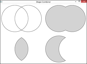
Figure 13-5: A program that combines circles with union, intersect, and subtract.
Listing 13-2: The Shape Combiner program
import javafx.application.*;
import javafx.stage.*;
import javafx.scene.*;
import javafx.scene.shape.*;
import javafx.scene.paint.*;
public class ShapeCombiner extends Application
{
public static void main(String[] args)
{
launch(args);
}
@Override public void start(Stage primaryStage)
{
Group group1 = new Group(); →17
Circle circle1 = new Circle(110, 110, 100); →19
Circle circle2 = new Circle(210, 110, 100);
Circle circle3 = new Circle(440, 110, 100);
Circle circle4 = new Circle(540, 110, 100);
Circle circle5 = new Circle(110, 340, 100);
Circle circle6 = new Circle(210, 340, 100);
Circle circle7 = new Circle(440, 340, 100);
Circle circle8 = new Circle(540, 340, 100);
Shape union = Shape.union(circle3, circle4); →28
Shape intersect = Shape.intersect(circle5, circle6); →29
Shape subtract = Shape.subtract(circle7, circle8); →30
circle1.setFill(null); →32
circle1.setStroke(Color.BLACK);
circle2.setFill(null);
circle2.setStroke(Color.BLACK);
union.setStroke(Color.BLACK); →38
union.setFill(Color.LIGHTGRAY);
intersect.setStroke(Color.BLACK);
intersect.setFill(Color.LIGHTGRAY);
subtract.setStroke(Color.BLACK);
subtract.setFill(Color.LIGHTGRAY);
group1.getChildren().addAll(circle1, circle2, union, →47
intersect, subtract);
Scene scene = new Scene(group1);
primaryStage.setScene(scene);
primaryStage.setTitle("Shape Combiner");
primaryStage.show();
}
}
The following paragraphs describe the high points of the Shape Combiner program:
→ 17: A Group is created to hold the circles and composite shapes displayed by this program.
→ 19: These lines create eight circle objects, positioned on the scene in four groups of two.
→ 28: The Shape.union method is called to create a Shape object named union by combining circles 3 and 4.
→ 29: The Shape.intersect method is called to create a Shape object named intersect that is the overlapping portions of circles 5 and 6.
→ 30: The Shape.subtract method is called to create a Shape object named subtract that is the result of subtracting circle 8 from circle 7.
→ 32: These lines set the stroke and fill for circles 1 and 2.
→ 38: These lines set the stroke and fill for the union, intersect, and subtract shapes.
→ 47: This line adds circles 1 and 2 as well as the union, intersect, and subtract shapes to the group container, which serves as the root container for the scene.