
Chapter 5
Modeling in 3ds Max: Part II
Building models in 3D is as simple as building them out of clay, wood, or metal. Using 3ds Max to model something may not be as tactile as physically building it, but the same concepts apply: You have to identify how the model is shaped and figure out how to break it down into manageable parts that you can piece together into the final form.
Instead of using traditional tools to hammer or chisel or weld a shape into form, you will use the vertices of the geometry to shape the CG model. As you have seen, 3ds Max’s polygon toolset is quite robust.
In this chapter, we will tackle a more complex model with a children’s Red Rocket ride-on toy. We will use the Editable Poly toolset, the Lathe and Bevel modifiers, and the Loft compound object to create the toy. We will also examine the use of QuickSlice (to add detail) and Booleans (to easily create interesting indentations on an existing surface).
The topic of this chapter is as follows:
- Building the Red Rocket
Using reference materials will help you efficiently create your 3D model and achieve a good likeness in your end result. The temptation to just “wing it” and start building the objects is strong, especially when time is short and you’re raring to go. This temptation should always be suppressed in deference to a well thought-out approach to the task. Sketches, photographs, and drawings can all be used as resources for the modeling process; you can place them in a scene as backdrop images and model over them. Not only are references useful for giving you a clear direction in which to head, but you can use references directly in 3ds Max to help you model. Photos, especially those taken from different sides of the intended model, can be added to a scene as background images to help you shape your model.
Creating Planes and Adding Materials
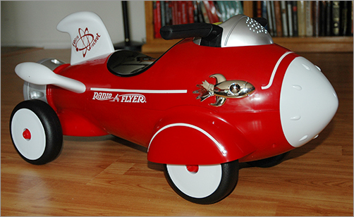
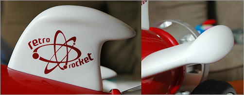
There are two common approaches to adding backdrop images for modeling in 3ds Max. You can use the viewport’s Background Image feature or you can use the crossing boxes technique, which involves placing the reference images on crossing plane objects or thin boxes in the scene. In this exercise, we’ll use the crossing boxes technique as the starting point to build a child’s rocket ride-on toy, as shown in Figure 5-1.
Before you begin, download the Red Rocket folder from this book’s companion web page (www.sybex.com/go/intro3dsmax2011) to your hard drive where you keep your other 3ds Max projects. Set your project folder to the Red Rocket project you just downloaded (Application Menu ⇒ Manage ⇒ Set Project Folder).
1. Open a new 3ds Max file by choosing Application Menu ⇒ New.
Figure 5-1: A photograph of a child’s Red Rocket toy
2. Go to Customize ⇒ Units Setup. In the dialog box, set the units to Generic Units and click OK. Generic units are the 3ds Max’s default units—one 3ds Max unit equals one inch.
3. Go to the Create panel to create a box (click the Geometry button (![]() ) and, under Standard Primitives in the pull-down menu, click the Box button.
) and, under Standard Primitives in the pull-down menu, click the Box button.
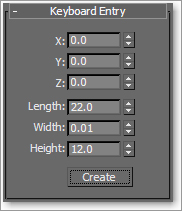
Instead of creating the box with the click and drag method, we will use the Keyboard Entry rollout, as shown in Figure 5-2. Expand the Keyboard Entry rollout. Make sure the Perspective view is selected. Leave the XYZ parameters all set to 0; this will place the box at the origin point of your scene. Change the Length, Width, and Height parameters to the following and click Create:
Length: 22
Width: 0.01
Height: 12
Figure 5-2: The Keyboard Entry rollout for creating the box
4. When you click Create, 3ds Max will create the image-plane box we’ll use for the side view. Rename the Box001 object Side View.
5. Activate the Top viewport, then repeat step 3 to create another flat box, which you’ll use for the Top View image-plane box. Use the following parameters.
Length: 22
Width: 12
Height: 0.01
Rename the box Top View.
6. Activate the Front viewport, and then repeat step 3 one last time to create the image-plane box for the front view of the rocket toy. Use the following parameters. Rename the box Front View.
Length: 12
Width: 12
Height: 0.01
7. Move the Front View box up six units in the Z-axis to raise it so the bottom edge is directly on the Home Grid, as shown in Figure 5-3. Switch all the viewports to Smooth + Highlights (F3) and Zoom Extents All to see everything.
8. In Windows Explorer, navigate to the sceneassetsimages folder in the Red Rocket directory that you downloaded to your hard drive. In this folder, you will find three reference JPEG images, one for each of the three image-plane box views we just created in the scene. Select the Top View reference image (called TOP VIEW.jpg); drag it into the Top viewport in 3ds Max, and drop it onto the Top View image-plane box. This will automatically place the image onto the box, so the image will be viewable in the viewport.
Figure 5-3: The Front View box is moved up.

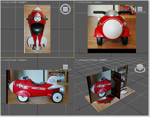
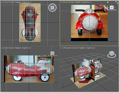
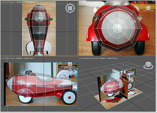
9. Repeat the previous step to place SIDE VIEW.jpg onto the Side View image-plane box in the Left viewport and place FRONT VIEW.jpg onto the Front View image-plane box in the Front viewport. Figure 5-4 shows the image-plane boxes with the reference images applied.
If, for some reason, the image on your Top View object seems to be the reverse of what is shown in the book, simply rotate the Top View object to line it up the way the images appear in this chapter. Also, you may notice black bars appearing in the images. They are intended to allow the images to better line up with each other.
10. If you need to, adjust the placement of the Front View image-plane box so the proportions of the rocket match up. The bottom of the wheels and the top of the handlebars should line up in all three images. Just move the box using the Select and Move tool. You will need to use the Orbit viewport navigation tool to rotate the view so that the image-plane boxes can be viewed from different sides to get them aligned.
If the rocket images do not show up in the viewport after you drop them onto the boxes, make sure the viewport is set to Smooth + Highlights and try again.
Figure 5-4: The image-plane boxes with the rocket views applied
Organizing Your Scene File
The next step is to begin organizing your scene file. We are going to use the Layer Manager (shown in Figure 5-5), which is a floating dialog window where you can organize objects into layers (something like how you can organize Adobe Photoshop layers, but for 3D objects).The objects you create have common properties for their associated layer, including color, renderability, and display settings. An object can assume these properties directly from the layer on which you create it. Using layers makes it easier to manage the information in your scenes. For example, layers are often used to control the visibility of objects in a populated scene so you can focus on certain objects without the clutter of having the entire scene all visible at once. Layers can also control the color of your objects’ wireframes and the frozen and hidden state of objects to better help you organize your scene.
In the Layer Manager, when you create new layers, 3ds Max names them sequentially by default. These default names are Layer01, Layer02, and so on. After creating a layer, you should rename it something less generic so you can track your layers better. Click the layer in the Layer Manager to highlight the layer, and click again to change its name.
Figure 5-5: The Layer Manager
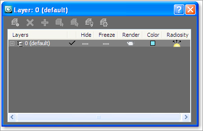
Figure 5-6: Changing layer names

3ds Max assigns a random color to all new layers. You can accept the default settings or specify other colors by clicking on the little color swatch. For more on the Layer Manager see Chapter 3, “The 3ds Max Interface.”
In the following steps, we will use the Layer Manager to organize our scene:
1. Select the image-plane boxes.
2. On the Main toolbar, click the Layer Manager icon (![]() ).
).
3. In the Layer Manager, click Create New Layer (![]() ) to create a new layer. Click Layer01 and enter Image Planes as its new name (see Figure 5-6).
) to create a new layer. Click Layer01 and enter Image Planes as its new name (see Figure 5-6).
4. If you create the new layer with the objects you want in the layer selected, they automatically will be added to the layer.
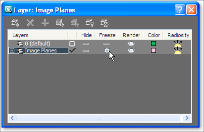
5. When we work in the scene, we do not want to select the image-plane boxes. There is no need to adjust them as you model. In the Layer Manager, this is made very simple. Click the icon in the Freeze column in the Image Planes layer, as shown in Figure 5-7. The layer will be frozen so its objects cannot be selected in the viewports. The frozen boxes will turn gray, and the images will disappear.
Figure 5-7: The Freeze icon
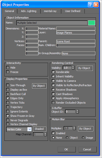
6. Open the layer by clicking the plus sign. You will see the objects listed. Select all three image-plane boxes by holding down the Ctrl key and clicking the objects. Click the cube symbol next to one of the image-plane box names. This will bring up the Object Properties dialog box for that image-plane box for that layer, as shown in Figure 5-8. In the Display Properties area, uncheck the Show Frozen in Gray box. When you press OK, the image will show up on the plane. Because all three objects were selected, this option was applied to all three.
Figure 5-8: Use the Object Properties list to turn on the image display for the frozen image-plane boxes.
7. Any objects you create will automatically be assigned to the selected layer, so in the Layer Manager make sure to double-click on Layer01 (default) to set it as the current layer, and then close the Layer Manager.
As you continue modeling the rocket, you will frequently use the Layer Manager to help manage the scene.
Creating the Body
To begin the body of the rocket, you can load the scene file Rocket_00.max from the Scenes folder of the Red Rocket project that you downloaded from the web page. In the following steps, we will begin the rocket model:
1. Start in the Front viewport. In the Create panel, click the Geometry icon (![]() ) and select Extended Primitives in the drop-down menu. Click to activate the Capsule tool, and then create a Capsule object with Keyboard Entry values set to a Radius of 3 and a Height of 21. Remember to use the Front viewport so that the capsule is created oriented as shown in Figure 5-9.
) and select Extended Primitives in the drop-down menu. Click to activate the Capsule tool, and then create a Capsule object with Keyboard Entry values set to a Radius of 3 and a Height of 21. Remember to use the Front viewport so that the capsule is created oriented as shown in Figure 5-9.
Figure 5-9: Capsule in the Front viewport

2. In the Modify panel set the capsule’s Sides to 8 and Height Segs to 6. Uncheck the Smooth option; we will do the smoothing later.
3. Rename the capsule Rocket Body. Make Rocket Body see-through in all the viewports by pressing Alt+X. This way you will be able to see the image-plane box through the geometry.
4. Line up the rocket body with the Side, Top, and Front image-plane boxes, matching the rocket body to the front end of the image as shown in Figure 5-10.
Figure 5-10: Line up the Rocket Body object to the image-plane box views.
5. In the Graphite Modeling Tools ribbon, click on the Polygon Modeling panel ⇒ Convert to Poly, as shown in Figure 5-11.
Figure 5-11: Convert to an editable poly.

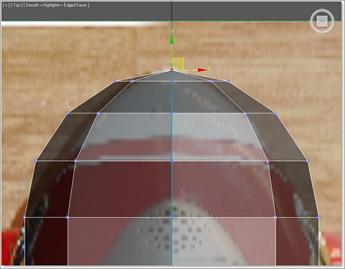
6. Enter the Vertex sub-object mode and select the vertex at the very front tip of the rocket body (as shown in Figure 5-12).
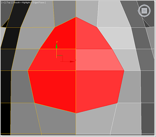
7. With the vertex selected, go into the Modify panel. In the Soft Selection rollout, click on Use Soft Selection and set the Falloff to 6.0. Now switch to the Scale tool (R). We need to scale along the XY-axis, which is a nonuniform scale. Do the scale in the Front viewport, center your cursor over the Transform gizmo’s XY-axis as shown in Figure 5-13, and scale while watching the Top viewport. Scale down to create a more pointed front.
Figure 5-12: Select the vertex at the very front tip.
8. Selecting some of the front vertices section by section in the Top viewport, scale and/or move the rest of the front to match the front of the rocket in the Top View image-plane box, as shown in Figure 5-14.
9. Using vertices with or without soft selection (using a Falloff setting if needed), shape the rest of the body to the shape in the three image-plane boxes (as shown later, in Figure 5-16). Don’t worry about the back end of the rocket body just yet; we’ll tackle that in the next step.
10. When you have the general shape of the body of the rocket, go into Polygon mode, select the polys at the rounded back end of your shape, as shown in Figure 5-15, and delete them by pressing Delete.
Figure 5-16 shows the result of the deletion.
Figure 5-13: Center your cursor over the Transform gizmo’s XY-axis (shows as an angled yellow bar).
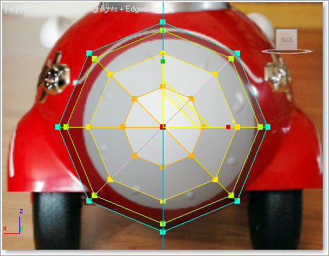
Figure 5-14: Select some front vertices and scale and/or move to match.

Figure 5-15: Select the end polys to cut off the end of the rocket body.
Figure 5-16: The result of deleting the end of the capsule for the tail section of the rocket
Smoothing the Body
The body looks very rough and chunky right now. To smooth out the rough model, we will use Subdivision Surfaces. A subdivision surface is a surface that has been divided into more faces to create a smoother surface while still retaining the object’s general shape. You subdivide to add more detail to an object or to smooth out the shape. In 3ds Max, Subdivision Surfaces is a rollout in the Modify panel for an editable poly.
The following steps will guide you through the process of smoothing out the rocket’s body shape.
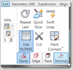
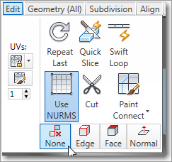
Figure 5-17: NURMS subdivides polys, and smooths.
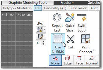
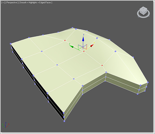
1. With the rocket body selected, go to the Graphite Modeling Tools ribbon, and in the Edit tab click on the Use NURMS button, as shown in Figure 5-17. This subdivides the polygons and relaxes the transition between polygons, smoothing the shape of the rocket’s body. If you are still in Polygon mode, you will see the orange Subdivision Surfaces (SDS) cage appear. This cage allows you to continue editing the body’s overall shape by just selecting the lower-res cage’s polys and editing them. This lets you affect its broader form without having to select many more polys of the smoothed version.
2. Enter Polygon sub-object mode (press 4) with the rocket’s body selected, select the polygons on the rocket body’s right side (as shown in Figure 5-18), and delete them.
Figure 5-18: Select the polygons as shown.

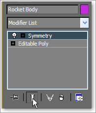
3. Go to the top level of the editable poly (press 6). Go to the Modify panel and from the Modifier list choose the Symmetry modifier. In the Symmetry parameters, choose X as the Mirror Axis and check the Flip box. This creates a mirrored copy of that half of the body. Using Symmetry allows you to make changes to the original side of the body and automatically have those changes mirrored to the other side.
When you go back to editing the mesh, the mirrored half of the rocket will disappear. To stop this from occurring, press the Show End Result button, which is in the line of icons below the Modifier Stack, shown in Figure 5-19.
Figure 5-19: Show End Result button
4. In the Layer Manager, create a new layer called Rocket, and assign the Rocket Body object to the new layer.
Adding Detail to the Rocket Body
The wheel wells on the front sides of the body are the first details we will add. To create the wheel wells, we need to add some more segments to the main body. To do this, we will use a new tool from the Graphite Modeling Tools, called SwiftLoop. This tool is quite popular! It places edge loops with just a click, replacing what used to take more effort. As you move the mouse cursor over your object, a real-time preview shows where the loop will be created when you click.
You will be adding edges as shown in Figure 5-20 using the following steps.
Figure 5-20: Use the SwiftLoop tool to add detail to these areas on the rocket’s body.

The SwiftLoop tool can be used in any of the sub-object modes or in the top level with no sub-object mode selected.
1. Go into the Layer Manager and hide the Image Planes layer. With the rocket’s body selected, in the Graphite Modeling Tools ribbon, go to Polygon mode, then open the Edit panel and select SwiftLoop, as shown in Figure 5-21. Move your cursor over to the rocket, and you will see a preview of where a loop will eventually be placed. When the loop is in the correct place just click, and it will be added. You want to match placement of four new loops with those shown in Figure 5-20.
Figure 5-21: Select SwiftLoop.

Now that the new loops are in, you will see there is a little issue. The front-end vertex of the rocket doesn’t connect to the newly added SwiftLoop edge, as seen in Figure 5-22. All of those edges really need to come to a point at the tip, so we will continue the new segment to the tip manually, using the Connect vertex function in the next step.
2. Press the 1 key to enter Vertex sub-object mode, and turn off Soft Selection. Select the two vertices shown in Figure 5-23.
Figure 5-22: Incomplete edge loop
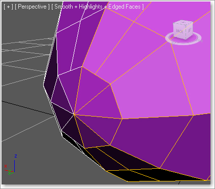
Figure 5-23: Select the two vertices.

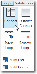
3. Go to the Graphite Modeling Tools ribbon, and in the Loops panel click on the Connect tool as shown in Figure 5-24. This will complete the loop.
Figure 5-24: Connect tool
4. Repeat the same with the vertex on the lower side of the rocket. The completed loops are shown in Figure 5-25.
Figure 5-25: Completed vertex connection

Creating the Wheel Well
Now that we have created more detail on the mesh, we can mold the wheel wells as shown on the actual rocket in Figure 5-26.
Figure 5-26: The rocket’s wheel wells
You can continue with your own scene file (just make sure to turn off NURMS smoothing before you continue), or use the scene file Rocket_01.max from the Scenes folder in the Red Rocket project that you downloaded to your hard drive.
Here are the steps to follow.
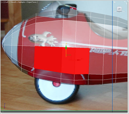
1. Select the rocket and change to Polygon sub-object mode (press 4), and from the Left viewport select the three polygons in the middle of the body, as shown in Figure 5-27.
Figure 5-27: Change to the Polygon sub-object mode and select these three polygons.
2. In the Graphite Modeling Tools ribbon in the Polygons panel, click the Extrude Settings button, as shown in Figure 5-28, to bring up the caddy.
Figure 5-28: Click the Extrude Settings button in the Graphite Modeling Tools ribbon.

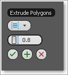
In the Extrude Polygons caddy, set Extrusion Type to Group and Height to 0.8, as shown in Figure 5-29. Click OK.
Figure 5-29: Setting the extrusion parameters in the caddy
3. Now select all the polygons that were created with the extrude operation, shown in Figure 5-30 (on the left). If you don’t have the back view already visible, right-click in the Front viewport to activate it, press the V key, and select Back View to switch to the Back viewport. Turn on the Image Plane layer in the Layer Manager to see the image-plane boxes. Then, in the Back viewport, use the Rotate and Move tools to align the polygons so that they line up with the wheel well in the Front View image-plane box, as shown in Figure 5-30 (on the right).
4. Switch to Vertex mode. Use a window selection to select and move the second row of vertices from the bottom of the rocket body out to the right and slightly down, as shown in Figure 5-31. This evens out the bottom part of the body to give it a more rounded look. If we left those vertices where they were, that part of the body would appear lopsided. And who wants that?
Let’s apply Subdivision Surfaces to the model again to see how the wheel wells looks when smoothed. There are still several things that we need to do to improve the look of the body.
First, the wheel well polygons need to be moved down and reshaped to have an arch on the top.
Figure 5-30: Use the Rotate and Move tools.

Figure 5-31: Round out the bottom of the rocket’s body.

Exit sub-object mode and select Rocket Body, and in the Graphite Modeling Tools ribbon click the Use NURMS button in the Edit panel. Now, when it is subdivided it looks a bit better. Figure 5-32 shows the rocket after NURMS has been enabled for the mesh.
Now we need to hollow out the wheel well. Follow these steps.
1. Disable NURMS smoothing by clicking on the Use NURMS button again.
2. Enter Polygon sub-object mode. Select the polygons at the bottom side of the wheel well, as shown in Figure 5-33.
3. In the Graphite Modeling Tools ribbon go to the Polygons tab and click the Bevel Settings button. Set the Outline to –0.1 and the Height to 0, then click Apply and Continue. Reset Outline to 0.0, then set Height to –0.7 to push in the area, then click OK. Finally, delete the inside polygon as shown in Figure 5-34.
We don’t need to create the inside of the wheel well because we are not going to see it. We extruded into the wheel well in step 3 to make a solid lip at the wheel well, but it only needs to go halfway up.
4. Check to make sure that the new edges don’t poke through the mesh (see Figure 5-35). If any do, select the vertices and move them inward.
Figure 5-32: After Use NURMS is applied, the smoothed rocket looks better (shown here without the background reference image planes).
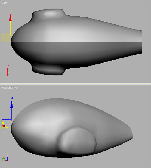
Figure 5-33: Select the polygons at the bottom of the wheel well.
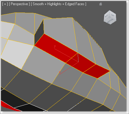
Figure 5-34: The wheel well after polygons are deleted. You may see some geometry poking through the side, as shown here.
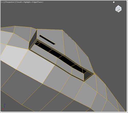
Figure 5-35: The geometry is poking through the outside!
5. Enable NURMS smoothing, and your rocket body should resemble the one in Figure 5-36. Make sure to disable NURMS smoothing before you continue with the rest of the exercise.
6. Save your work.
Figure 5-36: The smoothed wheel wells look pretty good.
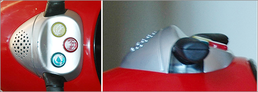
Creating the Control Panel
We’ll now create the control panel for the rocket, as shown in Figure 5-37. You can continue with your own scene file or use the scene file Rocket_02.max from the Scenes folder in the Red Rocket project you downloaded from the web page.
Figure 5-37: The control panel
1. To create the control panel, we need to add one more segment along the top of the body for extra mesh detail, as you can see in Figure 5-38. To Create the new edge, we will try another method of segmenting new polygons: Connect.
Connect creates new edges between pairs of selected edges. In the Connect Edges caddy, shown in Figure 5-39, you can specify the number of edges to be created. Using the Pinch and Slide values, you can define the spacing between those new edges.
2. Switch to Edge sub-object mode (press 2). In the Top viewport, select the edge at the top center of the Rocket, as shown in Figure 5-40. Go to the Graphite Modeling Tools ribbon, and in the Modify Selection panel click on the Ring button. This selects all the edges from top to bottom.
Figure 5-38: Add a segment line using the Connect tool to create extra mesh detail for the control panel.
Figure 5-39: The Connect Edges caddy

Figure 5-40: Select the edge at the top center.
3. Stay in Edge mode, and in the Graphite Modeling Tools ribbon ⇒ Loops tabs select the Connect button. This adds a single new edge.
4. Now we are going to create a new segment line vertically down the length of the rocket body, as shown in Figure 5-41, using the same technique as in the previous exercise (the Connect tool).
Figure 5-41: Add a lengthwise cut line to the rocket body.

5. This time, select one of the horizontal edges at the top of the rocket (as shown in Figure 5-42). Then in the Modify Selection panel in the Graphite Modeling Tools ribbon, select Ring to automatically select all the horizontal edges above and below your initial selection. Go to the Loops panel and click Connect to create the new cut line shown in Figure 5-41.
Now we see the same problem at the tip of the rocket that we saw in the last exercise. Going back to Figure 5-23 and reading from there will guide you through connecting these two vertices.
6. With the new vertices along this lengthwise cut line, in the Top viewport move the vertices to fit the shape of the control panel, as shown in the Top View image-plane box. See Figure 5-43.
Figure 5-42: Select one of the horizontal edges at the top.
Figure 5-43: Shape the new vertices around the control panel in the Top viewport.

7. Switch to Polygon sub-object mode and select the control panel polygons shown in Figure 5-44.
Figure 5-44: Select the control panel polygons.
8. Go to the Graphite Modeling Tools ribbon and click the Extrude Settings button in the Polygons panel. Extrude the polys with an Amount of 1.0 and with the Extrude Type set to Group, and click OK.
If you look at the top view of the rocket, you will see the new extrusion where it meets the reference half of the rocket body, as shown in Figure 5-45.
The two sides where you extruded should split away from each other. Remember that the two sides are being stitched together to form the whole body using the Symmetry modifier, so all we need to do is make sure that all the vertices of the original side are aligned in the middle. For the original rocket half, you’ll need to delete the polygons along the middle and move the vertices together. We’ll do this in the following steps.
9. Select the middle inside polygons, as shown in Figure 5-46, and delete them.
10. Switch to Vertex mode and select the vertices shown in Figure 5-47. Move them along the X-axis to the middle, where the original and the reference halves meet, as shown in Figure 5-48. The problem is fixed! When the body halves are stitched together later, the body mesh will look seamless.
Figure 5-45: The top view of the rocket.
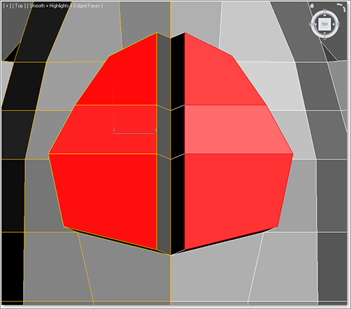
Figure 5-46: Select the middle inside polygons.
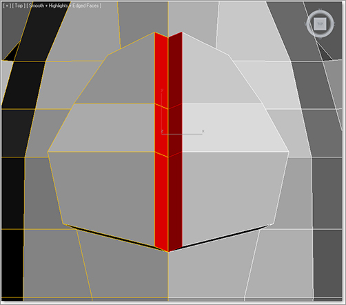
Figure 5-47: Select the vertices shown here.
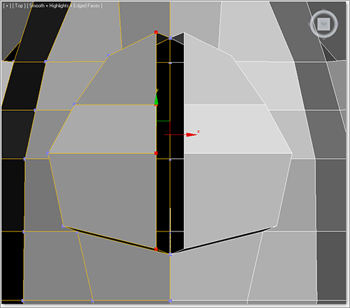
Figure 5-48: Line up the vertices to fix the split in the control panel between the two halves of the rocket body.

11. Make sure you are in Vertex mode. Using the Front, Side, and Top viewports, move the vertices of the control panel to line up with the real rocket’s control panel in the image-plane boxes, as shown in Figure 5-49.
Figure 5-49: Shape the vertices of the control panel to the outline shown in the image-plane boxes.
12. Let’s look at this rocket body smoothed. Go to the Edit panel in the Graphite Modeling Tools ribbon and click on the Use NURMS button to smooth the model again. It should look like Figure 5-50.
Figure 5-50: Use NURMS subdivision.
13. Use the cage to further edit the control panel to better fit the real control panel in the reference image-plane boxes.
You will see the Subdivision Surfaces cage as long as you are in Polygon mode.
When you disable NURMS, the polygons for the control panel will seem exaggerated, as shown in Figure 5-51, and will go beyond the outlines of the real control panel in the image-plane boxes.
Figure 5-51: The polygons appear exaggerated.

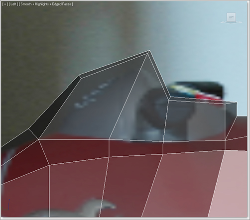
That is because the lower-resolution cage model is a rough shape before smoothing is applied to it. Once NURMS is enabled, it will smooth the detail down, shrinking it back from the cage’s shape a little. With NURMS smoothing enabled, the control panel will look like Figure 5-52 and will fit the real model.
Figure 5-52: The smoothed control panel as seen in profile

Creating the Back Wheel Axle Assembly
Let’s turn our attention to the back wheels. In the following steps, we will create the back axle assembly shown in Figure 5-53. You can use your own scene file or load the scene file Rocket_03.max from the Scenes folder in the Red Rocket project.
1. Disable smoothing by clicking the Use NURMS option and switch to Polygon sub-object mode. Change your Top viewport to a Bottom viewport. Also, hide the Image Planes layer in the Layer Manager to get them out of the way.
2. Select the two polygons at the back bottom of the body, shown in Figure 5-54, and extrude them with an Amount of 0.6.
3. The extruded polygons will split at the middle where the original and mirrored reference halves of the body meet, as they did with the control panel earlier in this exercise. Move the vertices and fix the seam in the center the same way you did for the control panel. Make sure to delete the unneeded inside polygons as you did with the control panel. You can see the result in Figure 5-55.
Figure 5-53: The back wheels
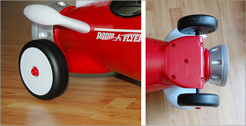
Figure 5-54: Select the two polygons at the back bottom of the body.
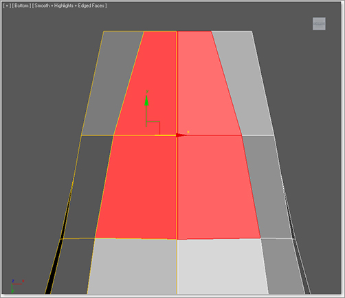
Figure 5-55: The result
4. Go into Vertex mode and adjust the extruded polygons of the back axle so that they have the shape of the axle from the Side View image-plane box, as shown in Figure 5-56.
Figure 5-56: Adjust the extruded polygons to better fit the shape of the back.
5. Select the polys on the side of the extruded polygons and extrude them with an Amount of 0.6, as shown in Figure 5-57.
Figure 5-57: An extrusion with an Amount of 0.6
6. Rearrange the vertices to create a small delta wing coming off the bottom/side of the body, as shown in Figure 5-58.
Figure 5-58: Create a small delta wing.
7. Turn on NURMS again to see the smoothed results shown in Figure 5-59.
Figure 5-59: The rocket body is taking shape.
8. While still in NURMS, try moving the cage vertices to sculpt the back wheel axle. Save your work.
The body is finished for now. Later we will create the seat and add the small lip that connects the thruster to the back.
Creating the Fins
In this section, we will create the top and side fins for the rocket body, shown in Figure 5-60. Load the scene file Rocket_04.max from the Scenes folder in the Red Rocket project you downloaded from the web page, or continue to work with your own scene file.
Figure 5-60: The top and side fins
The fins have specific features—rounded corners and edges—that require us to create them as a modified primitive. There is a nice dip in the wing and a bulbous rounded end, so we will need extra segments across the top. Follow these steps to create the fins.
1. In the Create panel, click the Geometry icon and select Standard Primitives from the drop-down menu. Click to create a Box primitive. Switch the Bottom viewport back to the Top viewport if you need to. In the Top viewport over the wing on the image-plane box, click and drag to create a box with the following parameters: Length: 4.5, Width: 3.2, Height: 0.4, Length Segs: 4, Width Segs: 4, and Height Segs: 2.
2. Press Alt+X to make the model see-through (if it isn’t already). Now you should be able to see the image-plane box under the box you just created for the side fin.
3. Select and rotate the box –15 degrees on the Z-axis to line up with the side fin. Convert the box to an editable poly and enter Vertex mode.
4. Using the Top viewport, move the vertices to match the fin in the Top View image-plane box, as shown in Figure 5-61.
Figure 5-61: Move the vertices to match the fin.

5. On the side of the fin model, select the center row of vertices, then go to the Edit panel of the Graphite Modeling Tools ribbon and click the Constrain to Normal button as- shown in Figure 5-62. Move the vertices, which are now constrained along their individual normal (meaning they will move only perpendicularly out from their current surface location), to create the nice round edge shown in Figure 5-63.
Figure 5-62: The Constrain to Normal button in the Edit panel of the Graphite Modeling Tools ribbon
6. Select the vertices along the top and bottom rows at the edge of the fin model. The Constrain to Normal setting is still turned on. Now move the vertices up along the Z-axis, and they will move away from the center to create the bulbous rounded end of the fin (Figure 5-64).
7. Choose the row of vertices shown in Figure 5-65. (Make sure you select both rows on the top and bottom sides of the box.)
8. With Constrain to Normal in the Edit panel still turned on, move this set of vertices along the Z-axis, as you did in step 6 to increase the bulbous end of the fin, as shown in Figure 5-66. Move that row of vertices on the X-axis a little closer to the tip of the fin. Figure 5-67 shows how you can adjust the next row of vertices down a little bit into the fin to further accentuate the bulbous part of the fin.
Figure 5-63: Move the vertices to create a nice round edge.
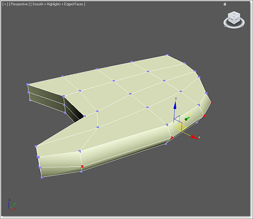
Figure 5-64: Create the rounded end of the fin.

Figure 5-65: Choose the row of vertices here.
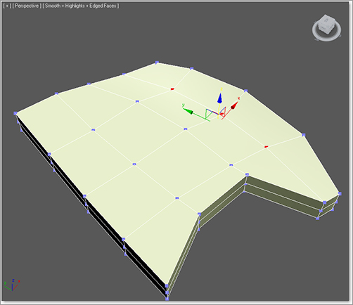
Figure 5-66: Move up more vertices to create the rounded tip of the fin.
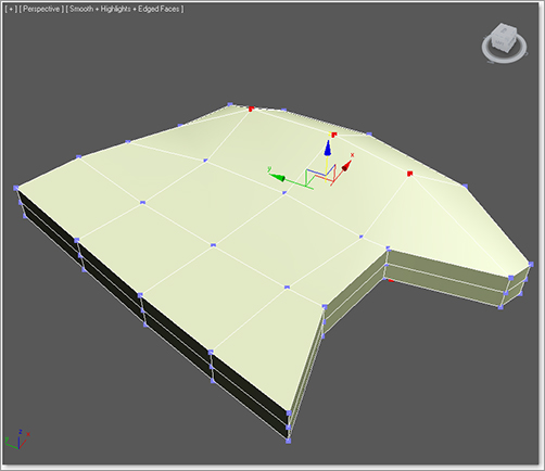
Figure 5-67: Adjust vertices to achieve the bulbous shape of the fin’s edge.

9. In the Edit panel turn the Constrain setting back to None, as shown in Figure 5-68. Then select the row shown in Figure 5-69, and move the vertices closer to the tip of the fin to slightly narrow the bulbous end.
Figure 5-68: Set the constraint back to None.
10. Enable Use NURMS to smooth the fin as you did for the Rocket body, and check your work against the fin shown in Figure 5-70 . Remember to disable smoothing when you’re done.
To set up a hot key for NURMS, go to Customize ⇒ Customize User Interface ⇒ Keyboard tab ⇒ Main UI group ⇒ All Commands ⇒ NURMS toggle (Poly) and assign a hot key combination such as Ctrl+Alt+Y. (We personally used Ctrl+Alt+Y.) As a general rule, it is best to learn the default UI before assigning any hot keys.
11. Exit sub-object mode, select the fin, and select the Move tool. Press and hold the Shift key and move the fin to create a copy of the fin. In the Clone Options dialog that opens when you release the mouse button, click Copy in the Object area. You now have two fins. Clone one more fin so you have three fins. Select the fins and add them to the Rocket layer in the Layer Manager.
12. Select the first fin and line it up to the body of the rocket on the side on which you are currently working. Select a copied fin, and orient it to line up with the fin on the other side of the body.
Figure 5-69: Refine the shape of the fin’s bulbous tip.
13. Select the third fin and place it on top of the rocket body as the vertical fin. Line it up with the images of the real rocket. Figure 5-71 shows you the fins placed on the rocket.
14. Save your work.
Figure 5-70: Smoothing makes the fin look more like the real fin on the red rocket.
Figure 5-71: The fins are in place.

The Scenes folder of the Red Rocket project has a completed fin model. The “Merging Objects into a Scene” sidebar discusses how to import a finished model into an existing scene and merge it with the current objects.
Merging Objects into a Scene
Let’s try to merge an external model into this scene. Pretend that you have created a fin model for the red rocket in a different scene file. You can import that fin into your current scene with the rocket body instead of creating a whole new Fin object in this scene. In 3ds Max, this procedure is called merging.
1. Save your work.
2. Delete the three fins you’ve already created for your rocket.
3. Click the Application menu ⇒ Import ⇒ Merge and navigate to the Fin.max file in the Scenes folder in the Red Rocket project.
4. Click Open. The Merge dialog window opens, as shown here.

5. Select the Fin object from the dialog window and click OK. The Fin object will appear in your scene as the top center fin of the rocket.
Instead of creating the fins from scratch, you can clone and position the fin to create the side fins, or you can load your previous scene file and continue with the Red Rocket exercise. If you keep the merged fins, make sure to add them to the Rocket layer in the Layer Manager.
Creating the Thruster
The back end of the rocket toy is the round thruster shown in Figure 5-72. You can continue with your own scene file or load Rocket_05.max from the Scenes folder in the Red Rocket project you downloaded from the web page.
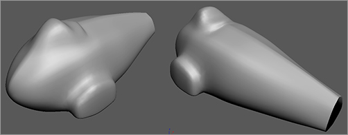
Figure 5-72: The thruster seen from above and below

You will create the thruster using the Lathe modifier technique, which you used to create the knobs for the dresser model in Chapter 4, “Modeling in 3ds Max: Part I.” Using Lathe works only when the object to be modeled is round and has the same look and detail all the way around. Like we did with the dresser knob we created in Chapter 4, we will use splines—more specifically the Line tool—to fashion the profile of the thruster. The Line tool in 3ds Max is like the Pen tool in Photoshop or the Mask tool in After Effects: It creates a 2D shape with no depth. The Lathe modifier then creates a 3D object by rotating that shape about one of the three axes (X, Y, or Z).
Using Lathe for the Thruster Shape
We need to identify the profile and draw it with the Line tool.
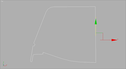
1. The profile shape we need to use is laid out in Figure 5-73. In the Create panel, click the Shapes icon. There you will find the Line tool button. Click Line, and in the Front viewport lay out a profile similar in shape to Figure 5-73. The shape will make more sense once you see it lathed.
Figure 5-73: This shape will be used to lathe the thruster for the rocket.
If you prefer not to create the shape, you can merge in an existing shape for the thruster’s profile. Click the Application menu ⇒ Import ⇒ Merge, navigate to the Scenes folder of the Red Rocket project, and open the file called ThrusterProfile.max. Select the Exhaust Profile Line object and click OK. The profile shape will merge into your scene.
Figure 5-74: The lathe is rotating about the wrong axis.

2. Once you have created the spline or merged the existing one into the scene, select the spline, go to the Modify panel, and add the Lathe modifier to the line.
Don’t worry if you get something like the lathe shown in Figure 5-74, which is rotating about the wrong axis. Currently, the profile line is rotating about the axis at the center of the line shape. We need the axis of rotation to be at the inside edge of the profile shape.
3. Go to the Modify panel and make sure the lathe is selected. Under the Parameters rollout, in the Align section click the Min button (shown in Figure 5-75). This moves the rotation axis for the profile to the inside edge.
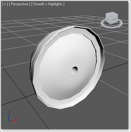
The lathed object should look more like the thruster but will have a big hole in the middle (Figure 5-76). This is also an axis issue. You need to adjust the lathe’s axis of rotation to get rid of the hole.
Figure 5-75: Click the Min button.

Figure 5-76: The lathe is starting to look more like the thruster.
4. Go to the Modifier Stack, expand the Lathe modifier (click the plus sign to the left of the Lathe entry in the Modifier Stack), and select Axis. We now are in the lathe’s sub-object mode. Go to the Perspective viewport and move the Transform gizmo to the left (or right, depending on your orientation) along the X-axis until the hole is closed to the naked eye.
Be cautious with step 4. You can’t actually close the hole this way; you can only make it smaller. If you cross over the line, the normals will flip on the entire object. Get the hole as small as you can; when the thruster is finished, you can add a Cap Holes modifier from the Modifier List.
5. Go back to the Lathe parameters and change Segments to 20. This will help the thruster look less faceted than it does right now, but it will look a bit chunky on the edges. Don’t be too concerned with that; the thrusters will not be seen close up in this scenario. Use the Segments parameter to make your lathes look only as smooth as needed for your shot.
6. Name your thruster geometry Thruster, and add it to the Rocket layer in the Layer Manager.
7. Move it to the back of the rocket body, according to the reference images.
Using Booleans for the Thruster Detail
Take another look at Figure 5-72. The thruster has indented detail running around the side. We will create this in our model using a Boolean operation. A Boolean operation is a geometric operation that creates a shape from the addition of two shapes, the subtraction of one shape from another, or the common intersection of two shapes.
In theory, we will need to subtract the indented shape from the thruster mesh we have created so far. We’ll start by creating the shape we need to use by cutting it out of the thruster mesh. In Figure 5-72, you can see that the top of the shape indented into the thruster side has flat corners, the bottom corners are rounded, and the whole rectangle shape tapers.
You can continue with your own work or open Rocket_06.max in the Scenes folder of the Red Rocket project to catch up to this point.
If you don’t want to spend time creating the thruster detail objects, you can merge the premade model from the scene file Thruster Detail.max in the Scenes folder of the Red Rocket project.
1. Let’s make the work area a little easier to navigate by hiding some of the rocket parts. Open the Layer Manager and click to hide the Image Planes layer, then expand the Rocket layer, and click in the Hide column to hide the three fins and the rocket body. You can unhide them from the Layer Manager at any time.
If you don’t want to create the splines, you can merge an already created spline from the scene file Thruster Detail Spline.max in the Scenes folder of the Red Rocket project. If you merge in this file, you can skip to step 3.
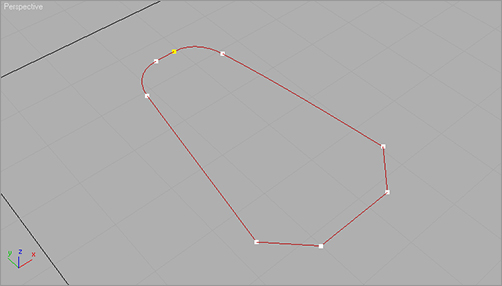
2. Go to the Create panel and, under Shapes, select Rectangle. Click and drag in the Top viewport to create a rectangle with Length 0.74 and Width 0.42. Move the rectangle above the thruster geometry we just lathed, as shown in Figure 5-77.
Figure 5-77: Move the rectangle above the thruster geometry.

3. Center your cursor over the wireframe of the rectangle and right-click; choose Convert To ⇒ Convert to Editable Spline, as shown in Figure 5-78. Converting to an editable spline will give you access to the sub-object modes, as you saw in the previous chapter, and it will let you edit the shape for the detail you need in the thruster.
Figure 5-78: Convert the rectangle to an editable spline.
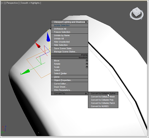
Figure 5-79: Enter a value of 0.04 to get the resulting chamfered corners at the bottom.

4. Go into Vertex mode for the rectangle spline and select the bottom two vertices. Go into the Geometry rollout, enter a value of 0.04 for Chamfer, and press Enter (Figure 5-79).
5. Select the two top vertices individually and move them closer together so that the rectangle tapers at that end. Select both of the top vertices, and in the Geometry rollout enter a value of 0.1 for Fillet. Click the Fillet button to round out the top of the spline, as shown in Figure 5-80.
Figure 5-80: Click the Fillet button to round out the top of the spline.
Watch carefully to make sure the chamfer and fillet in steps 4 and 5 don’t create overlapping vertices. Too much of a good thing can cause trouble.
6. Exit Vertex mode by clicking on Editable Spline in the Modifier Stack.
7. With the spline selected, go into the Modifier List and choose Extrude. Set the Amount to 0.4. We will use this to indent into the thruster sides.
8. Line up the thruster detail object with the thruster as shown in Figure 5-81. Center the object on top of the thruster for best results in the following steps.
Figure 5-81: Center the thruster detail object on the thruster.

There are eight indentations all around the thruster, so we are going to copy one and array the indentation around the thruster eight times. To make it easier, move the pivot point of the Boolean object to the center of the thruster; this will enable the object to be copied nicely around the thruster.
9. With the thruster![]() ) and click Affect Pivot Only.
) and click Affect Pivot Only.
10. We want to make sure the pivot is in the center of the exhaust. Select the thruster, and in the Main toolbar select the Align tool (![]() ), making sure that Affect Pivot Only is active. Leave the dialog box settings at their default values and press OK.
), making sure that Affect Pivot Only is active. Leave the dialog box settings at their default values and press OK.
The pivot should be the only thing that moves. If the object moves, Undo (Ctrl+Z) and try the step again.
Figure 5-82: Clone Options dialog box

11. Click Affect Pivot Only again to disable it. Press the A key to turn on Angle Snap, then change to the Rotate tool. While holding down the Shift key, rotate the thruster detail object 45 degrees in either direction around the thruster dish. When you release the mouse button, the Clone Options dialog box should open. Select Copy, enter a value of 7 for Number of Copies (Figure 5-82), and press OK. This will place seven copies of the object, each at 45 degrees of rotation around the thruster, making a total of eight objects that are 360 degrees around, as shown in Figure 5-83.
Figure 5-83: Seven copies of the object

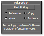
12. Select the thruster, go to the Create panel, and select Geometry. Choose Compound Objects from the pull-down menu and then click the ProBoolean button. Click the Start Picking button, as shown in Figure 5-84. Move to the thruster detail objects and click on each one to subtract from the thruster.
Figure 5-84: Using Start Picking to add detail to the Thruster object
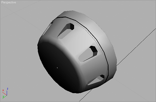
Your thruster should now have the indentations shown in Figure 5-85.
13. Click Start Picking to turn the feature off. Then unhide the other parts of the rocket to see how everything looks so far. You can do this through the Layer Manager window. Save your work.
Figure 5-85: The thruster with its indentation detail
Further Body Work
We need to add some finishing touches to the body of the rocket. You can continue working with your own scene file or load Rocket_07.max from the Scenes folder in the Red Rocket project.
You should see a seam running along the top middle of the body(Figure 5-86). To fix this, we need to bring those vertices in toward the center of the body until the seam disappears.
Figure 5-86: A seam runs down the middle of the rocket body.

1. Select the rocket, then in the Modifier Stack select Vertex mode. The mirrored side of the body will disappear because we are lower in the Modifier Stack. If you want the Symmety to remain, click on the Show End Result button (![]() ), which you will find in the row of icons below the Modifier Stack.
), which you will find in the row of icons below the Modifier Stack.
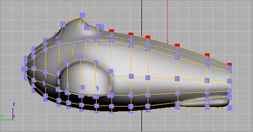
2. Select the vertices that run along the middle. Select and move a few at a time. From the side view, you can see that those vertices stick up farther than the row below; this is what causes the ridge. Make the vertices level with the row of vertices below them by moving them along the Z-axis, as shown in Figure 5-87. (This step will be easier if you turn off Use NURMS in the Subdivision Surface rollout.)
Figure 5-87: Make the vertices level with the row of vertices below them.
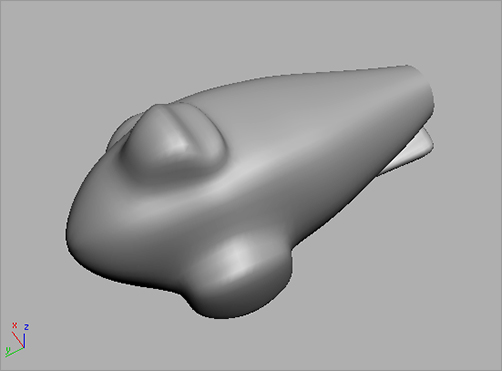
3. Go to Symmetry up in the Modifier Stack to view the whole body without the seam. Turn smoothing back on if necessary (Figure 5-88).
Figure 5-88: The seam is gone!
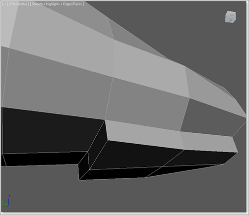
The next detail to manage is a small lip at the back end of the body (shown in Figure 5-89). We are doing the lip after we complete the body because this detail is easier to create after the body is stitched together.
Figure 5-89: The lip between the thruster and the rocket body

1. Turn off Use NURMS if it’s currently enabled. Also, hide the fins and the thruster.
2. Make sure the body is selected (with the Symmetry modifier). Go to the Graphite Modeling Tools ribbon, and in the Polygon Modeling menu click on Collapse Stack.
3. In the Polygon Modeling panel, click on Border mode and select the edge in the back of the body, as shown in Figure 5-90.
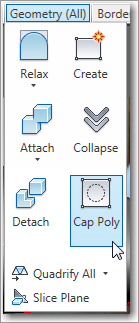
4. Go to the Geometry (All) panel in the Graphite Modeling Tools ribbon and click Cap Poly, as shown in Figure 5-91. This will create a poly where the hole was.
Figure 5-90: Select the edge in the back of the body.

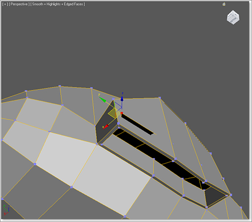
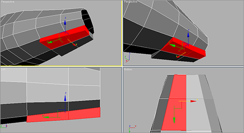
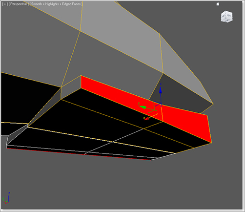
5. Switch to Polygon sub-object mode and select the new polygon. Go to the Polygons panel of the Graphite Modeling Tools ribbon and click the Bevel Settings to open the Bevel caddy. We will do four bevels through the open Bevel caddy. Between each bevel, make sure you click Apply and Continue, not OK. This will apply your bevel but keep the caddy open for more.
Figure 5-91: Click Cap Poly in the Geometry (All) panel.
6. Make four bevels with the following values:
| Bevel No. | Height | Outline Amount |
| 1 | 0.05 | 0.3 |
| 2 | 0.2 | 0.1 |
| 3 | 0.2 | –0.1 |
| 4 | 0.05 | –0.3 |
7. Click on the Poly button to go to the top level of the Edit Poly modifier.
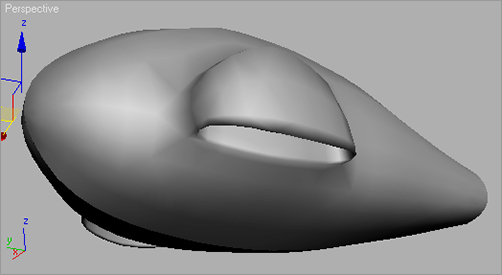
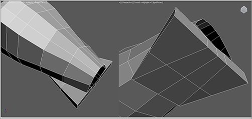
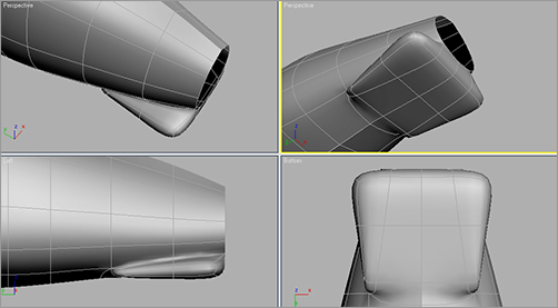
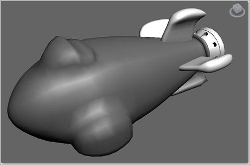
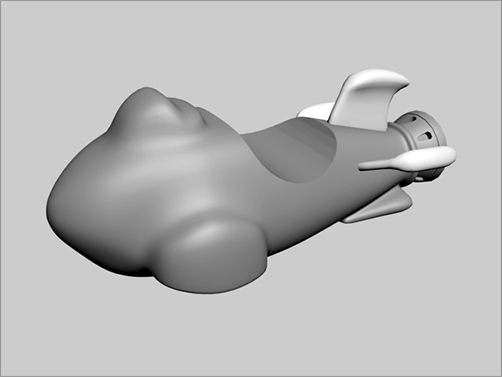
Now you can unhide the thruster and the fins. Make sure everything lines up, and render if you’d like (Figure 5-92). (See Chapter 11, “3ds Max Rendering,” for more about rendering.)
Figure 5-92: The finished rocket body
Making the Wheels
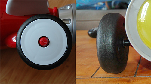
We are in the home stretch. The wheels, the handlebars, and the buttons for the control panel are all that are left to model. In this section, we will model the wheels shown in Figure 5-93.
You can continue with your own scene file or load Rocket_08.max from the Scenes folder in the Red Rocket project.
Figure 5-93: The wheels of the rocket are next.
If you don’t want to create the wheels, you can merge the wheels using an already created model from the scene file Wheel.max in the Scenes folder of the Red Rocket project.
Creating the First Wheel
The wheels are created using the same general technique as the body and fins: Select the polygons of a standard/extended primitive and edit them. This time we are going to use a chamfer cylinder.
1. If the image planes are hidden, unhide them for the side view. In the Layer Manager, make sure the default layer is checked. This will ensure that the object you create for the wheel will not be in the layer that has the hidden Rocket objects.
2. Go to the Create panel. In the drop-down menu, select Extended Primitives and click to create a chamfer cylinder.
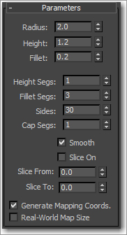
3. To get the side of the wheel to finish, click and drag to create the circle of the cylinder, then release the mouse button. Drag and click the mouse again to set the depth of the cylinder, and finally drag the mouse a third time to set the amount of the chamfer. Click to set the final shape in the Left viewport. Go to the Modify panel and set the Chamfer Cylinder parameters shown in Figure 5-94.
| Parameter | Value |
| Radius | 2 |
| Height | 1.2 |
| Fillet | 0.2 |
| Height Segs | 1 |
| Fillet Segs | 3 |
| Sides | 30 |
| Cap Segs | 1 |
| Smooth | Checked |
| Slice On | Unchecked |
Figure 5-94: Set the Chamfer Cylinder parameters as shown.
4. Go to the Graphite Modeling Tools ribbon, and in the Polygon Modeling panel click Convert to Poly. Go into Vertex mode and select the vertex on the front in the center, as shown in Figure 5-95.
5. Go to the Graphite Modeling Tools ribbon’s Vertices panel and click on the Chamfer Settings button. Set the Vertex Chamfer Amount to 0.4 and click OK.
6. Switch to Polygon mode and select the new center polygon, as shown in Figure 5-96.
7. Go to the Polygons panel and open the Bevel Settings caddy. Set Height to –0.4 and Outline to 0.0, and click Apply and Continue to create one bevel. Then set Height to 0.5 and Outline to –0.12 and click OK to create a second bevel.
8. Now change the viewport so you can see the back of the wheel.
9. Go back into Vertex mode and select the center vertex. Go to the Vertices panel and click the Chamfer Settings button. Set the Vertex Chamfer Amount to 0.2 and click OK.
10. Switch back to Polygon mode and select the new center polygon. In the Polygons panel, extrude the polygon with an Amount of 3.0. You can see the completed wheel in Figure 5-97.
Figure 5-95: Select the vertex on the front in the center.

Figure 5-96: Select the new center polygon.
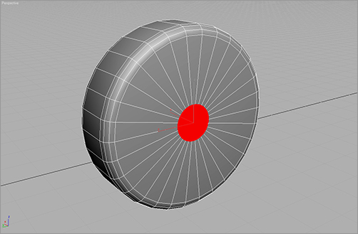
Figure 5-97: The completed wheel

Placing the Wheels
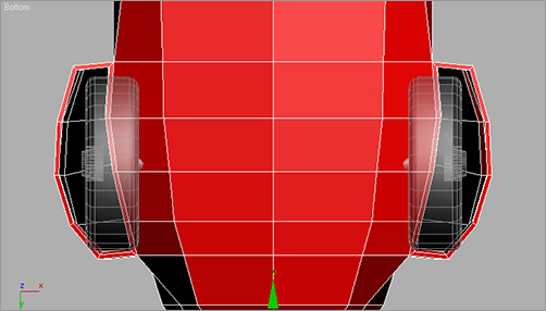
One wheel is done! Now exit the Polygon level and make three clones for the front and back wheels. Unhide the rocket body and place the wheels at the wheel wells. Don’t worry if the front wheels don’t fit perfectly and happen to penetrate the body’s geometry. It was hard to tell how big to make the wheel wells until we had the wheels. We will fix that here:
1. Select the rocket body and, in the Edit menu of the Graphite Modeling Tools ribbon, click Use NURMS to turn it off.
2. The body of the rocket will appear low poly again, as you can see in Figure 5-98. It’s usually easier to model in the low-poly version rather than the smoothed one.
Figure 5-98: The body of the rocket in low poly shown in a Bottom viewport
3. Go into Vertex mode.
4. Change any viewport to a bottom view. Select the vertices on the inside of the wheel well and move them to make the opening larger so the wheels can fit, as shown in Figure 5-99.
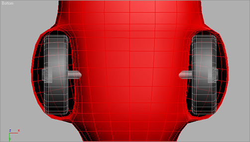
5. Click the Use NURMS button to turn it back on. See if the wheels fit with the body when it is smoothed as shown in Figure 5-100.
Figure 5-99: Select the vertices on the inside walls of the wheel well and move them in closer to the centerline of the rocket body to give the wheels room.
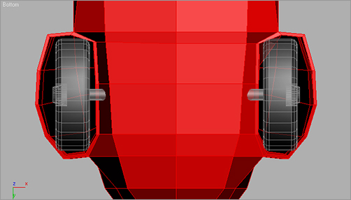
Figure 5-100: Make sure the wheels fit into the wheel wells.
One last thing you can do is to give your new wheels proper names (we used Wheel01, Wheel02, Wheel03, and Wheel04) and place them in the Rocket Layer by selecting all the wheels, clicking on the Rocket layer, and then clicking on the plus sign (+) in the Layers toolbar.
Getting a Handle on Things
Figure 5-101: The handlebars help prevent calamities of the falling kind.
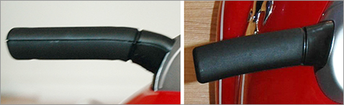
The red rocket has a set of handlebars just as a bike does. They help keep the driver (usually a child) from face planting every time he or she gets on it. As funny as that may be, a parent can watch it only so many times. This is why most grownups find the handlebars (shown in Figure 5-101) to be the most important part of the rocket. We will model them now.
The handlebars will be created using a modeling technique called lofting, which creates a shape that is extruded along a path. Each handlebar is a compound object that uses one shape as a profile and another as the path to form a 3D surface or object.
Lofting
The Loft compound object has many features and only a few restrictions. The Shape object can be complex, consisting of several noncontiguous splines and even nested splines. A new Shape object can be selected at any point along the path, and the cross-section will automatically transition from one shape to the next. Any 2D shape can be used as the Shape object, but only a shape that consists of a single spline can be used as the Path object.
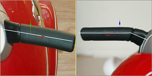
Creating the Path
Take another look at Figure 5-101 and imagine a straight line passing through the middle of one of the handlebars. This is the path we want to create.
You can continue with your own scene file or load Rocket_09.max from the Scenes folder in the Red Rocket project. You can hide the objects in the scene at this point to help keep an uncluttered workspace.
Merge the scene file Handle Bar Spline.max from the Scenes folder of the Red Rocket project if you don’t want to create the path yourself.
1. Start by going to the Create panel. Click the Shapes icon and select the Line tool.
2. In the Back viewport, against the image of the front view of the rocket, click to place the line’s first point where the handlebar meets the control panel. Move the cursor to where the handlebar bends, and create another point. Place a final point where the handlebar ends, as shown in Figure 5-102, and right-click to create the line. You may need to move the line forward in the Top viewport to get the proper alignment shown in Figure 5-102.
Figure 5-102: Place a final point where the handle ends.
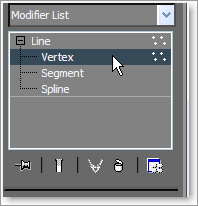
3. Move to the Modify panel and enter Vertex mode for the line, as shown in Figure 5-103. Select the middle vertex, go to the Fillet parameter in the Geometry rollout, and enter 0.1. This will add a smooth corner to the bend.
Figure 5-103: Enter Vertex mode for the line.
Creating the Shape
Now that we have the path for the loft, we need the profile shape, which is a cross-section of the handlebar. This shape is an oval with a flat top, as shown in Figure 5-104.
To create this shape, follow these steps:
1. Exit Vertex mode. Create a Circle shape from the Create panel and convert it to an editable spline.
Figure 5-104: An oval with a flat top

2. Go into Vertex mode, select the top vertex, and delete it to flatten the top.
Next, we will create the Loft object.
3. Exit Vertex mode then select the path spline for the handlebar and go to the Create menu. Click Geometry ⇒ Compound Objects ⇒ Loft.
4. Because we started the lofting process with the handlebar’s path line, we only need to let 3ds Max know which shape to use. In the Modify panel go to the Creation Method rollout (Figure 5-105), and select Get Shape.
Figure 5-105: Select Get Shape from the Creation Method rollout.

5. Select the handlebar shape in a viewport to use as the loft’s shape.
Editing the Loft Object
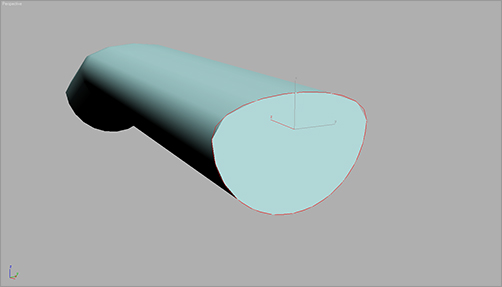
In Figure 5-106, you can see the loft’s path and cross-section shape as well as the resulting Loft object.
Figure 5-106: The loft lives!
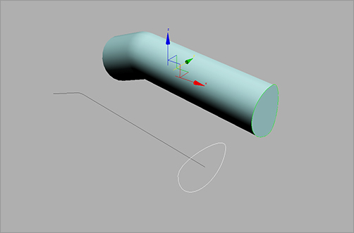
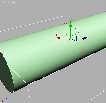
In this example the shape is rotated 90 degrees along the path, putting the handle on its side, as you can see in Figure 5-107.
Figure 5-107: The handlebar is oriented incorrectly, with the broad flat side facing the rider.

The shape needs to be turned to make the broad flat side point up, as shown in Figure 5-108.
Figure 5-108: You need to rotate the shape so the broad flat side faces up.
To edit the loft, we will go into its sub-object mode. The sub-objects of a loft are the path and the shape.
The original splines were instanced when the loft was created, so they are still connected to the loft. This means changes made at the sub-object level on the splines will be transferred to the lofted object. If necessary, you can alter the shape of the path line or shape splines and the loft will change accordingly. You cannot, however, move or rotate the path or shape splines to affect the shape of the loft. You must use Move or Rotate at the sub-object level of the loft instead.
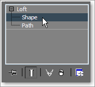
1. Go to the Modify panel and expand the Loft object in the Modifier Stack.
2. Go into the Shape sub-object mode (Figure 5-109).
Figure 5-109: The Shape sub-object mode
3. In a viewport, select the loft’s shape at the end of the Loft object. The shape will turn red when it is selected, as shown before in Figure 5-107. The shape spline is the thin, smoother line in this grayscale figure.
4. Select the Rotate tool and rotate the shape on the loft –90 degrees. The entire loft will be updated, as shown earlier in Figure 5-108.
Adding Detail
The next step is to create the subtle curves and dips of the handlebars. The outside end of the real handlebar is curved. There is a groove toward the middle, and the handle tapers up where it meets the control panel. To look this good, the handlebar we’ve created needs more than one cross-section. With a Loft compound object in 3ds Max, you can have any number of cross-sections for your loft, and they can be of varying shapes.
To edit a loft for these details, we are going to add more shapes along the path, and then edit those shapes to taste.
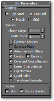
1. Go back to the top level of the Loft object in the Modify panel, and go to the Skin Parameters rollout. This is where you can manage the Steps (subdivisions) in the loft. By default, there is a value of 5 for both the Shape Steps and the Path Steps. The Shape Steps here are fine, but the Path Steps value is too high. To fix this, turn Path Steps down to 1, as shown in Figure 5-110. If there are too many steps in your loft, it will get too heavy and dense to model.
Figure 5-110: Reduce the Path Steps.
If you prefer, you can merge the scene file Handle Bar.max from the Red Rocket project to complete the one handlebar or to check your own work.
2. Go back to Shape mode and select the shape. Using the Move tool, center the cursor over the Z-axis wire of the Transform gizmo that is connected to the shape.
3. We need to make copies of the Shapes so we can taper down the end of the handlebar. Shift+click and drag the gizmo to move the shape just a little bit up the body of the handlebar to make a copy of the loft shape, as shown in Figure 5-111. The loft shape is shown as a dashed red line.
Figure 5-111: Make a copy of the loft shape.
4. In the Copy Shape dialog box, choose Copy, then click OK. Repeat these steps twice to end up with three copies, and place them close to the end of the handle, as shown in Figure 5-112. Switch to the Scale tool, and scale the outside shape down 30 percent and the middle shape down 10 percent. Leave the last inside shape alone, which should create a nice curved taper at the end of the handlebar.
5. Select the inside shape on the loft, and make four more copies in a row close to where the bar curves (Figure 5-113). Select the two inside copies and scale them both down 20 percent. This will create the groove toward the center of the handlebars.
6. Select the shape closest to the bend, and make a copy. Move it all the way to the other end of the object, away from the tapered tip. This is where it will meet the body of the rocket. Select the Scale tool, and scale this end shape up 50 percent. Exit the Loft’s sub-object mode.
7. If any parts of the rocket are hidden, unhide them and see how the handlebars line up. You will probably agree that there is room for improvement (Figure 5-114).
Figure 5-112: Place copies of the loft’s shape close together at the end to taper them down.
Figure 5-113: Creating the groove

Figure 5-114: The handlebars will probably not line up with your rocket body right away.

8. Instead of rotating the Loft object, rotate the last shape at the end of the loft. Go back to sub-object mode and select the last shape to rotate to line up with the body, as shown in Figure 5-115.
9. Select the handlebar, and in the Main Toolbar click the Mirror icon (![]() ) to mirror a copy of the handle for the other side of the rocket. Place it as needed. Figure 5-116 shows the rocket with its handlebars.
) to mirror a copy of the handle for the other side of the rocket. Place it as needed. Figure 5-116 shows the rocket with its handlebars.
Figure 5-115: Rotate the end shape object to line up with the rocket body.
Figure 5-116: The rocket with the handlebars in place
Hold onto Your Seat
What fun would it be to ride a rocket standing up? Speaking from experience, it’s not fun. So let’s give our rocket model a nice comfy seat. Then we’ll be finished with the model!
You can continue with your own scene file or load Rocket_10.max from the Scenes folder in the Red Rocket project.
1. Using your own scene file or the provided Rocket_10.max scene, in the Left view create a cylinder with the following parameters shown in Figure 5-117.
| Parameter | Value |
| Radius | 3 |
| Height | 8 |
| Height Segments | 1 |
| Cap Segments | 1 |
| Sides | 40 |
| Smooth | Checked |
Figure 5-117: The Parameters rollout

2. From the side view, line up the cylinder so it is over the part of the rocket body where the seat would be (as shown in Figure 5-118).
Figure 5-118: Line up the cylinder with the seat area.

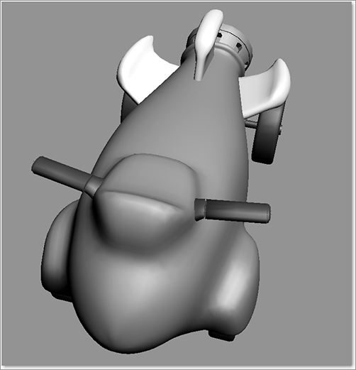
From the top view, the cylinder should be evenly spaced on both sides of the rocket (Figure 5-119).
3. Select the rocket body and before performing the Boolean operation, turn on Use NURMS as needed from the modeling ribbon. Then go to the Create menu ⇒ Geometry ⇒ Compound Objects ⇒ ProBoolean. Choose Start Picking from the Pick Boolean rollout, and then select the cylinder in a viewport. The cylinder will cut a seat into the rocket body as shown in Figure 5-120.
Figure 5-119: The top view of the cylinder
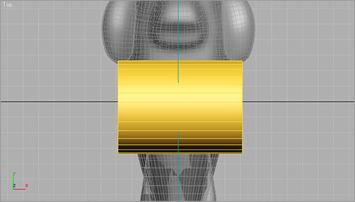
Figure 5-120: The seat is almost done.
Because the Boolean operation will collapse all the modifiers on the body, it is important that it be the last operation we perform on this model. We won’t want to make any changes to the body that would require access to its modifiers. Once any modifiers are collapsed, editing becomes difficult.
4. Convert the rocket body to an editable poly by right-clicking on the Rocket Body object and choosing Convert To: Convert to Editable Poly from the Quad menu.
5. Unhide any parts of the rocket that you may have hidden to clear your workspace.
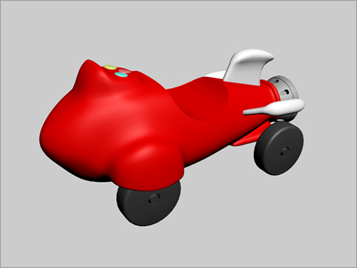
6. The control panel of the rocket needs some buttons. To add them, create a few chamfer cylinders and place them there. Now you’re really done! Figure 5-121 shows the completed red rocket with buttons in the control console.
7. Save your work; that is second nature to you by now—right?
Figure 5-121: The completed rocket!
Take it all in. As you can see, a fairly complex object is nothing more than a collection of simple shapes hammered, chiseled, cut, poked, and prodded into place. By learning how to dissect a complex object into its component shapes and learning how to view modeling an object as a series of steps, you will grow as a modeling artist.
When you built the red rocket, you employed several of the Editable Poly tools and ProBoolean functions you learned about in the previous chapter. The more you use these tools, the faster they will become an instinctive part of your workflow. You also used the very handy Symmetry modifier to cut your work on the body in half.
After setting up the scene with background images, you were able to line up model parts and build them to fit the actual object as you worked in the scene.
In the next chapter, we will continue exploring the Editable Poly tools while creating a lower polygon count character model, a commando soldier like you may find in a game.