Chapter 3
The 3ds Max Interface
This chapter explains the 3ds Max interface and its most commonly used windows and panels. You already mucked about in the UI when you built your mobile in the previous chapter. This chapter will go into more depth regarding some of the tasks you performed, and it will give you an overview of where things are and what they do. Furthermore, we’ll take a look at the commonly used windows and panels in 3ds Max and discuss how to operate them.
You can use this chapter as a reference as you work through the rest of this book. As you progress, you might want to check back here to review some of the information. It’s important to be in front of your computer when you read this chapter, so you can try things out as we discuss them in the book.
Topics in this chapter include the following:
- What am I looking at?
- Screen layout
- Command panels
- Controls at the bottom of the UI
- The viewports
- Managing scene objects
- Scene explorer
- The Quad menu and the caddy interface
When you start up 3ds Max, you will be looking at a screen full of buttons, icons, menus, tabs and panels, and an empty work area—how daunting! Although it may seem that there is no end to the switches and levers in 3ds Max, you’ll be able to master the UI with just a little experience. The more you use 3ds Max to create, the more comfortable you’ll become with the UI and all of its nuances. Before you know it, the UI will be a nonissue for you—just give it time and patience.
As with many other 3D applications, almost any command or tool can be accessed in a few different ways. For example, you can access some tools through icons in the Command panel by selecting them from the menu bar, by pressing a hot key, or by using context-sensitive Quad menus that appear when you right-click in the interface.
With so many different ways to perform any single function, how can you keep it all straight? Having a function or tool in several different places may seem like overload, but ultimately it gives users the most freedom to discover their preferred workflow. You may prefer to work mostly through the Command panel; others may find the menu bar easier to use. In either case, it’s important to first experience the most common way to use 3ds Max and then branch out and find your own preference. In this book, we will first present the most obvious way to access a function; later we will give you alternative ways (such as hot keys) that you can use to access that feature.
Please don’t obsess about all the information you’re about to encounter. It’s best to peruse this chapter at your own pace in front of your PC. Don’t worry about memorizing all the information on every button and panel. Each of the exercises in this book contains short descriptions of the UI elements you’ll use in that exercise. You can always refer back to this chapter for a more thorough explanation of a particular element. You should read through this chapter once to become familiar with where everything is and how everything works. Experience—and only experience—will show you how to make the tools work effectively; this chapter just shows you where they are.
In this chapter, you will find a fairly comprehensive explanation of 3ds Max’s UI that expands on what you learned in Chapter 2, “Your First 3ds Max Project.” If you skipped Chapter 2, please go back to it now and read the section called “The 3ds Max Interface” for a run-through of how to work in 3ds Max’s UI. Because experience will teach you so much more than just reading a text, it’s wise to give the UI a whirl. Go ahead and click on things and move around in the UI using this and the previous chapter as a guide.
Let’s take a quick look at how the screen is laid out. Figure 3-1 shows the initial 3ds Max screen.
Along the top of the UI, to the left, is the Quick Access toolbar where you have access to some of the most frequently used tools, including Open File, Save File, and the Undo Scene Operation and Redo Scene Operation buttons. Along the top of the UI, to the right, you will find the tools used to access the help files and to search for Autodesk-related content. At the top-left corner of the UI is the important Application Menu button with the 3ds Max logo on it (![]() ). The Application menu is the starting point for many operations in 3ds Max.
). The Application menu is the starting point for many operations in 3ds Max.
The menu bar runs from left to right near the top of the 3ds Max UI, just as with many other applications. Here you can access tons of features to help you with your scene creation and manipulation. Immediately under the menu bar is the Main toolbar, which contains the most frequently accessed tool icons. Everything from selecting objects to rendering the scene is in the Main toolbar for easy access.
Running down the right side of the 3ds Max UI is the Command panel. Object creation and manipulation tools are gathered here for your access. The Command panel, as you discovered in the previous chapter, is divided into tabs. Each tab has its own specific panel of tools, ranging from Create to Utilities.
The meat of the UI is in the viewports. These portals give you access to 3ds Max’s 3D space through orthographic and perspective views. These viewports are where you’ll do the bulk of your work. By using the mouse and key combinations, as you saw in the previous chapter, you can navigate through 3D space and around your scenes quite easily.
Figure 3-1: The default 3ds Max screen

Running across the bottom of the UI are the tools for changing time values , viewport navigation controls, and controls for animating.
Each of these UI sections is explained in more detail in the following pages, with a breakdown of the major components.
The following conventions are used throughout this book: Click—click with the left mouse button; MM click—click with the middle mouse button; RM click—click with the right mouse button.
The Application Menu
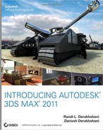
Common to many Autodesk products is the Application menu shown in Figure 3-2. From 3ds Max’s Application menu, you can access many file-related tools, including opening and saving files, importing other file types into 3ds Max, or exporting 3ds Max scenes in formats suitable for other programs. The Application menu is also where you will set up your project’s file structure and access information about the current scene.
When you first open the Application menu, the right pane lists the last 10 projects that were open. If you click the pin icon to the right of any file name (![]() ), that file’s position in the list becomes fixed until you unpin it to release it and allow the filename to scroll off the list as new files are accessed. Pausing the cursor on an item in the left pane displays that menu’s content in the right pane. You can use the Options button at the bottom of the Application menu to open the Preference Settings dialog box (Figure 3-3) and adjust the many file and system settings available in the program. You will use the Application menu considerably while working in 3ds Max.
), that file’s position in the list becomes fixed until you unpin it to release it and allow the filename to scroll off the list as new files are accessed. Pausing the cursor on an item in the left pane displays that menu’s content in the right pane. You can use the Options button at the bottom of the Application menu to open the Preference Settings dialog box (Figure 3-3) and adjust the many file and system settings available in the program. You will use the Application menu considerably while working in 3ds Max.
Figure 3-2: The Application menu
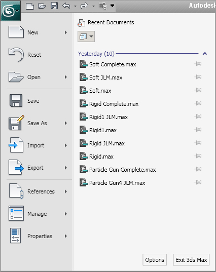
Figure 3-3: The Preference Settings dialog box

The Menu Bar
If you’ve ever played with a computer, you should be familiar with the layout of the menu bars, so let’s keep this brief. Here is a rundown of what to expect in each of the menus shown in Figure 3-4. Feel free to click along with the text to see for yourself what is in each menu.
Figure 3-4: The menu bar
Edit This contains the commands for editing and selecting objects in your scene. This is one of the areas where you will find the Undo/Redo functions, as well as easy selection methods such as Select All. Under the Select By submenu heading you can select objects in the scene using a certain criteria, such as by their color or name. Tools such as Move, Rotate, and Scale (transforms) are found here as well.
Tools This menu is where tools to manipulate your objects, such as Mirror and Align, are located. Many of these tools and functions are found on the Main toolbar and are also found in the Command panels. You’ll see how several of these tools operate in the coming chapters.
Group Grouping lets you combine two or more objects into a single grouped object. Groups can be open or closed, depending on how you want the user to access objects inside the group. You can also permanently break up the group by ungrouping or exploding (a command that dissolves all nested groups).
Views Options to set up and control viewports are located in this menu. From here, for example, you can disable the view of your gizmos (visual aids for using the transforms) in the viewports or toggle the ViewCube and SteeringWheels Viewport Navigation tools on and off.
If many of your tools, including the Main toolbar, Command panels, and viewport controls, disappear, you’re probably in Expert mode. Click Expert Mode on the Views menu to restore these tools or use the Ctrl+X shortcut key combination.
Create This menu gives tools for creating objects and is very extensive, with many submenus. Everything that you would ever want to create for your 3D scene is found here. Some of the objects you created in the previous chapter for your mobile can be created through this menu as well as through the Command panel’s Create panel, which you used in the Mobile exercise.
The Create menu is divided into 16 submenus. The main ones we will be using in this book are Standard Primitives, Extended Primitives, Shapes, Helpers, Lights, Cameras, and Particles.
Modifiers A modifier is a 3ds Max feature that controls and changes the basic structure of objects. Modifiers are used for modeling, animating, and adding special effects to objects. Through the Modifiers menu you can apply modifiers to selected objects in the scene. Once applied, modifiers are edited through the Modify panel.
Animation This menu has features for animation, constraints, controllers, and Inverse Kinematics (IK), a feature that is used for character animation.
Graph Editors These are floating windows for managing a scene, hierarchy, and animation. Graph Editors give you access to scene components in graphical layout for easy use. Everything from nodes (a node represents an object in 3ds Max) to animation curves are displayed. Animation curves are representations of animation expressed in mathematical graphs. It sounds harder than it is. You’ll see plenty of curves later in the book.
Rendering These commands are for scene rendering, setting up an environment and render effects, accessing video post for in-program compositing, and using a RAM player. The Material Editors are also accessed under this menu, as is the Material/Map Browser.
Customize This menu is for all things relating to user interface customization. This book will, for the most part, use the default layout for the 3ds Max UI, as that is most universal. Once you get a feeling for 3ds Max and are more comfortable with it, you’ll find yourself customizing the UI to your tastes.
MAXScript These are commands for working with MAXScript, which is a scripting language for 3ds Max. MAXScript allows you to automate certain functions and program parts of your scene as needed. MAXScript will not be covered in this book because it is an advanced feature set.
Help This provides access to online references, tutorials, and online support, and it is perhaps the most important menu in the program.
Main Toolbar
The Main toolbar puts the tools most commonly used in 3ds Max in a convenient location at the top of the interface (see Figure 3-5). This toolbar can be rearranged as a floating palette or docked on the bottom, left, or right side of the interface. To do this, place your cursor to the far-left side of the toolbar over the embossed vertical line. An icon of white boxes will appear next to your cursor. Click and drag to create a floating toolbar, or drag the toolbar to one side of the UI to dock it.
You can also right-click on the embossed vertical line for a pop-up window, giving you options for docking and floating the toolbar, as shown in Figure 3-6. All palettes and bars in the 3ds Max interface can be rearranged in this fashion.
Figure 3-5: The Main toolbar

Figure 3-6: You can float toolbars easily in 3ds Max.
If your screen does not show all the icons on the Main toolbar shown in Figure 3-5, don’t panic. Your display is probably set to a lower resolution than the width of the toolbar. In this case, you can scroll the toolbar left and right to expose the missing end of the toolbar. Place your cursor over an empty part of the toolbar (not on an icon), and it will turn into a hand icon. Click and drag to scroll the toolbar as needed.
The icons for the Main toolbar are as shown in the following tables. You should use them as references while you use this book; you don’t need to memorize everything here. For the most part, you will learn tools and functions in 3ds Max as you come across them in your work. Trying to memorize all the icons and their functions at the outset will just drive you nutty. Grab your mouse and click along through the examples in this chapter to get a feel for the icons.
Some icons, characterized by the small triangle in the lower-right corner, have flyouts. Flyouts ![]() are additional options for the tool that appear as a context menu of new icons when you click and hold the icon, as shown here for the Scale tool.
are additional options for the tool that appear as a context menu of new icons when you click and hold the icon, as shown here for the Scale tool.
Linking and Hierarchy Icons
Linking and Hierarchy tools are used to parent objects for animation; this is covered in the Mobile exercise in Chapter 8, “Introduction to Animation.” The icons are detailed here:
| Icon | Name | Function |
|
|
Select and Link | Allows you to create a hierarchical link of child and parent between objects. |
|
|
Unlink Selection | Allows you to remove the hierarchical link of child and parent between objects. |
|
|
Bind to Space Warp | Allows you to bind an object to a space warp effect (like gravity, wind, or displace). |
Selection Tool Icons
Selection tools allow you to select objects in a scene using different methods. The icons are detailed here:
| Icon | Name | Function |
|
|
Selection Filter | This drop-down list allows you to screen out certain objects that can be selected. For example, if you choose Geometry from the list, you will not be able to select anything other than geometry. This is particularly helpful when you have a very crowded scene. You can also create filter combinations such as cameras and lights together. |
|
|
Select Object | Allows you to select any object in your 3D scene by clicking it. |
|
|
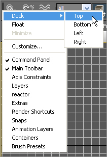
Select by Name | Allows you to select an object from a list within the Select from Scene dialog box, shown in Figure 3-7. The list contains objects currently in your scene and has filters for easy selection. For more on Select by Name, see the following section. |
|
|
Selection Region flyout | Gives you different ways to select objects by defining a region, which is done by clicking and dragging in a viewport. There are five region selection methods: Rectangular (the default), Circular, Fence, Lasso, and Paint. |
|
|
Window/Crossing Selection | Switches between Window and Crossing modes when you select by region. If you are in Window mode, it will select only objects that are entirely inside the window’s region. The default Crossing mode allows selection of objects that are touching the edge of the region. This tool will also work when you are selecting polygons in sub-object mode. |
Flyout icons show all the icons stacked below the current tool’s icon. This results in the current icon appearing twice in the flyout.
Figure 3-7: The Select by Name icon opens the Select from Scene dialog box.
Select by Name Icon
When you click the Select by Name icon in the Main toolbar, 3ds Max will bring up the Select from Scene dialog (Figure 3-5). With the Select from Scene dialog box, you can select any object in your scene by name, which is mighty handy if you have an extensive scene or need to select objects that are difficult to select in a viewport. While the window is open, you cannot edit anything in your scene until you click the Select button in the dialog to close the window. As you can see in Figure 3-7, the Select from Scene dialog box gives you information about the objects, such as their hierarchy and scene color.
This dialog box is a trimmed down version of the more powerful Scene Explorer window, covered at the end of this chapter.
Transformation Tools Icons
As you saw in the previous chapter, transformation tools move, rotate, and scale your objects. Their icons are detailed here:
| Icon | Name | Function |
|
|
Select and Move | Selects and moves objects. For all the transform tools (Move, Rotate, and Scale), you can click and drag a region box around the object or objects to select them. You can also invoke this tool with the W hot key. |
|
|
Select and Rotate | Selects and rotates objects. Clicking and dragging a region box around the object or objects selects them. You can also invoke this tool with the E hot key. |
|
|
Select and Scale flyout | This icon leads to a flyout where you can access two other Scale tools. The default Scale tool is the Uniform Scale tool (top icon), which allows you to scale along all three axes evenly. The middle icon in the flyout is the Non-uniform Scale tool, which allows you to scale along the axis you choose. The bottom icon is the Squash tool, which is a type of scale used mainly for the “squash and stretch” style of animation found in cartoons. When you are scaling down in one axis, it scales up in the other two, and vice versa. You can also invoke this tool with the R hot key. |
Coordinate Systems, Center Pivots, and Manipulator Icons
As you saw in the first chapter, coordinate systems define the axes that you use. The icons for this section of the Main toolbar are detailed here:
| Icon | Name | Function |
|
|
Reference Coordinate System menu | Allows you to choose which coordinate system you want to use. Coordinate systems are covered in depth at the end of Chapter 1, “Basic Concepts.” |
|
|
Use Center flyout | The tools accessed through this flyout allow you to determine the pivot point of an object for its transforms. The default setting, Use Pivot Point Center, is adequate for nearly all situations and is used throughout this book; however, this tool has a flyout that lets you relocate the center point of your transformation tools. You can use the tool if you have multiple objects selected. |
|
|
Select and Manipulate | Allows you to edit the parameters of certain objects, modifiers, and controllers by dragging manipulators in viewports. Manipulators are similar to the gizmos you’ve already used. Manipulators are not covered in this book. |
|
|
Keyboard Shortcut Override Toggle | Determines which set of keyboard shortcuts are currently useable; when it is disabled, only the main UI shortcuts are recognized. When it is enabled, the main UI and the functional area shortcuts are recognized. |
Snapping Icons
Snapping functions allow accurate placement of objects in your scene. When you enable a Snap function and then move an object, for example, 3ds Max will “snap” the object to points on the Home Grid or to other geometry in the scene. Because they let you snap to specific locations during creation and transformation of objects or sub-objects, Snaps give you control when you’re creating, moving, rotating, and scaling objects.
There are several different types of snaps; you can snap to a grid, pivot, or vertex among others. You can turn snaps on and off by clicking their icons in the Main toolbar or by pressing the S key while you are in the middle of a transform. We will be using snaps in the following chapters. Right-clicking on the Snaps Toggle button will open the Snaps tab of the Grid and Snap Settings dialog box shown in Figure 3-8. In it, you can select exactly how you want to snap.
| Icon | Name | Function |
|
|
Snaps Toggle flyout | The 2D Snap (top) icon allows you to snap to the Home Grid or to any shapes or geometry on the grid. The 2.5D Snap (middle) icon snaps vertices or edges of an object, but actually places the cursor at the projection of that point on the grid beyond it. The 3D Snap (bottom) icon will snap to any geometry in 3D space. |
|
|
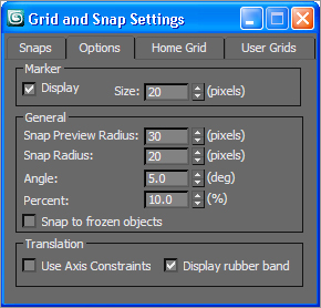
Angle Snap Toggle | Allows you to set the increment of rotation for rotating an object in a given axis. To set the increment you want to snap to, right-click the icon to open the Options tab of the Grid and Snap Settings dialog box, as shown in Figure 3-9. |
|
|
Percent Snap Toggle | Allows you to define a set scaling increment when you are scaling an object. |
|
|
Spinner Snap Toggle | Causes spinners to adjust in specific increments. You will run into spinners constantly in 3ds Max. Right-click the Spinner Snap Toggle to set the increment by which you want to increase or decrease a metric. |
Figure 3-8: The Grid and Snap Settings dialog box for the Snap functions
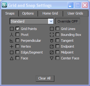
Figure 3-9: Right-click the Angle Snap toggle or Percent Snap toggle to set their parameters.
Named Selection Sets Icons
Figure 3-10: You can edit selection sets using this dialog box.
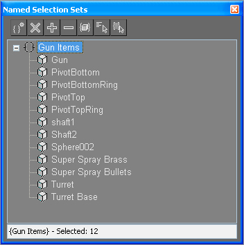
Selection sets are a way to easily select several objects at once. To create a selection set for your workflow, choose the objects you want it to contain, and then type a name for the set in the Named Selection Sets field. That name will be added to the drop-down menu so you can select all those objects in the set by selecting the set’s name. We will explore selection sets further in Chapter 5, “Modeling in 3ds Max: Part II.”
| Icon | Name | Function |
|
|
Edit Named Selection Sets | Launches a menu that allows you to organize your selection sets and the objects that are members of those sets. Click the plus (+) or minus (–) symbol to expand or collapse the object list for each set. The buttons along the top allow you to create or delete sets and add or remove objects. See Figure 3-10. |
|
|
Named Selection Sets | To create a named selection set, choose the objects for the selection set and enter a name for that set. |
Align and Mirror Icons
Figure 3-11: The Mirror dialog box

The Align and Mirror icons are next up in this Main toolbar discussion. The Mirror dialog box (Figure 3-11) allows you to mirror an object about a specific axis. In the dialog box, you can choose a mirror axis and the Offset amount—that is, how far the axis is from the pivot point. Before accessing the Mirror tool, use the Reference Coordinate System menu to select the coordinate system used to define the axis. You can either mirror the object or create a clone that is mirrored.
| Icon | Name | Function |
|
|
Mirror | Mirrors the selected object in the chosen axis. Can also copy a mirror of the object. |
|
|
Align flyout | The flyout gives you access to all the Align functions discussed in the following table. This Align icon is displayed by default. |
The Align tools found in the flyout allow you to line up your object as discussed in the following table. Select the object you want to align, click the appropriate Align tool icon from the flyout, and then click the target object to which the object is to be aligned.
| Icon | Name | Function |
|
|
Align | Once you click on the target object to align to, 3ds Max will open the Align Selection dialog box shown in Figure 3-12. Here you can choose which axis to align your selected object to as a function of position, rotation, or even scale. |
|
|
Quick Align | Lets you instantly align the position of the current selection to that of a target object. |
|
|
Normal Align | Lets you align two objects based on the direction of the normal of a face or selection on each object. A normal is an imaginary line that is perpendicular to a surface. |
|
|
Place Highlight | Lets you align a light to another object so that its highlight can be precisely positioned. |
|
|
Align Camera | Lets you align a camera to a selected face normal. |
|
|
Align to View | Lets you align an object with the current viewport. |
Figure 3-12: The Align Selection dialog box allows you to dictate how your objects are aligned.

Editing and Organizational Icons
Manage Layers, Graphite Modeling Tools, Curve Editor, and Schematic View are four editing and organizational tools in 3ds Max. We will cover each of them later in this chapter. Their icons are explained in this table.
| Icon | Name | Function |
|
|
Manage Layers | Lets you manage sets of objects in layers. Very useful for large scenes and complicated setups. |
|
|
Graphite Modeling Tools | Displays or hides the Graphite Modeling Tools ribbon and panels shown in Figure 3-13. |
|
|
Curve Editor | Allows you to edit animation by manipulating mathematical curves representing the changes over time. |
|
|
Schematic View | A node-based display of the objects in a scene that allows you to edit parameters as well as hierarchies. |
Figure 3-13: The Graphite Modeling tools

Graphite Modeling Tools
The Graphite Modeling tools is a section of the UI that provides you with a wide range of tools to make building and editing models in 3ds Max fast and easy. All the available tools are divided into tabs that are organized by function, and then further divided into panels. For example, the Graphite Modeling Tools tab contains the tools you use most often for polygon modeling and editing, organized into separate panels for easy, convenient access. In the following chapters, you will make copious use of the Graphite Modeling tools (see Figure 3-13). The panels found in the Polygon Modeling tab are:
- Polygon Modeling Panel
- Modify Selection Panel
- Edit Panel
- Geometry (All) Panel
- [Sub-object] Panel
- Loops Panel
- Additional Panels
The Material and Rendering Editors give you access to materials for shading and texturing, as well as options for rendering your scene. These functions will be covered later in this chapter, along with other commonly used dialog boxes and panels. Their icons are as follows:
| Icon | Name | Function |
|
|
Material Editor flyout | Accesses materials you can add to scene objects to give them their final look when rendered. The top icon opens the Material Editor and the bottom icon opens the newer Slate Material Editor. |
|
|
Render Setup | Opens the Render Setup dialog box, where you set the parameters for the next rendering. |
|
|
Rendered Frame Window | Displays or hides the Rendered Frame Window that shows the result of the last rendered frame |
|
|
Render flyout | Lets you render the scene using the current render settings without displaying the Render Setup dialog box. Render Production (top) uses the settings in the Render Setup dialog box. Render Iterative (middle) ignores settings that output the file and ActiveShade (bottom) keeps a constantly updated rendered window open. |
The Quick Access Toolbar
At the top-left corner of the UI is the Quick Access toolbar. This toolbar contains some of the most often-used, file-related tools in 3ds Max.
The File Control Icons
Rather than accessing the nested tools in the Application menu, the Quick Access toolbar contains the New Scene, Open File, and Save File tools, and, at the right end, the Project Folder tool. The icons are as follows:
| Icon | Name | Function |
|
|
New Scene | Starts a new 3ds Max scene. Existing objects and hierarchies can be carried over to the new scene. |
|
|
Open File | Opens an existing 3ds Max scene. |
|
|
Save File | Saves the file using the same filename. If the file has not been saved yet, the Save File As dialog box opens so that a filename and location can be entered. |
|
|
Project Folder | Opens the Browse for Folder dialog box, where the project folder is defined. |
Undo/Redo Icons
The Undo Scene Operation and Redo Scene Operation buttons (we’ll call the Undo and Redo from now on) are extremely useful in 3ds Max. You will find yourself painted into a corner many times—especially when you are first starting out—and Undo will let you back out of those corners. The icons are as follows:
| Icon | Name | Function |
|
|
Undo | Reverses the effect of the last action. Clicking the small arrow to the right shows a list of the previous actions that can be undone. |
|
|
Redo | Cancels the last Undo. Clicking the small arrow to the right shows a list of the previous actions that can be undone. |
|
|
Customize Quick Access Toolbar | At the far end of the Quick Access toolbar, this button is where you can set which tools are shown. |
The Information Center
Autodesk provides the Information Center, at the top-right of the UI, as the source of information from Autodesk regarding your software. This is also where you can manage your software subscription, if you have one, access the 3ds Max help files, and define a list of favorite articles to access quickly.
| Icon | Name | Function |
|
|
Search field | Type in a word or phrase to search for. |
|
|
Search | Searches the several locations for the word or phrase entered in the search field. |
|
|
Subscription Center | Displays links used to manage the software subscription program. |
|
|
Communication Center | This is where you access software-specific communications from Autodesk. |
|
|
Favorites | Contains links to user-specified articles for quick access. |
|
|
Help | Click the icon to access the 3ds Max help file or the arrow to display a list of the available help files. |
Whoa! Did You Get All That?
That was a lot to take in! Don’t worry. There is absolutely no need to memorize all this material. You will see most of these tools in action in the next few chapters, and before long, using them (and recognizing their icons) will be second nature to you. This part of the book is designed as a reference guide, so bookmark these pages for easy access later.
Everything you need to create, manipulate, and animate objects can be found here. As you saw in the previous chapter, the Command panel (shown in Figure 3-14) is divided into tabs according to function. This lets you access several commands and functions through the different panels that comprise a quick workflow in 3ds Max.
Figure 3-14: The Command panel

The function or toolset you need to access will determine which panel you need to click. The division of panel tabs is very instinctive and easy to decipher.
You can scroll up and down a panel to access tools that are not visible on the screen because the panel is too long vertically. When you encounter a panel that is longer than your screen, 3ds Max will display a thin vertical scroll bar on the right side. Your cursor will also turn into a hand that lets you click and drag the panel up and down.
You will be exposed to more panels as you progress through this book. Here is a rundown of the Command Panel functions and what they do. They are discussed in more detail in later sections of this chapter.
| Icon | Name | Function |
|
|
Create panel | Lets you create objects, lights, cameras, etc. |
|
|
Modify panel | Lets you apply and edit modifiers to objects. |
|
|
Hierarchy panel | Lets you adjust the hierarchy for objects and adjust their pivot points. |
|
|
Motion panel | Lets you access animation tools and functions. |
|
|
Display panel | Lets you access display options for scene objects. |
|
|
Utilities panel | Lets you access several functions of 3ds Max, such as motion capture utilities and the Asset Browser. |
Create Panel
The first panel, the Create panel, is used primarily for creating various objects for your scene. You can create seven categories of objects. The panels under the Create panel are detailed here:
| Icon | Name | Function |
|
|
Geometry | Lets you create renderable objects, such as primitives or parametric objects. |
|
|
Shapes | Lets you create 2D lines and splines of various shapes. |
|
|
Lights | 3ds Max lights can simulate real-world lights to illuminate objects in the scene. |
|
|
Camera | Lets you create cameras to view and render your 3D scene. |
|
|
Helpers | Helper objects are aids to constructing a scene. |
|
|
Space Warp | Space Warp objects deform the appearance of other objects. |
|
|
Systems | Catch-all panel containing functions such as Bones and Biped Animation tools, as well as lighting systems to simulate sun and daylight. |
Geometry
Figure 3-15: The Create Geometry category for the Create panel

The Geometry category in the Create panel is responsible for renderable objects, also known as primitives or parametric objects (objects whose parameters may be changed at any time to adjust their original shape or appearance). The default is Standard Primitives. Click on the drop-down window to access more object types, such as Extended Primitives, Compound Objects, and Particle Systems.
When you created the mobile in the previous chapter, you made the cylinders from the Geometry panel. You can access many other objects through the Create menu as well (Figure 3-15).
Shapes
Figure 3-16: Creating shapes in the Create panel
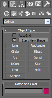
Shapes are 2D lines or splines that can be used as is. You can also use them to create 3D objects using modifiers, such as Extrude, as you saw in the Mobile exercise. You can use stock shapes, such as a circle or rectangle, or you can use the Line tool to create free-form shapes. Lines are used as components to create other objects. You can use splines to create motion paths, extrusions, lathes, lofts, and 3D objects. The drop-down menu will give you access to NURBS and Extended Splines. Figure 3-16 shows the Shapes Creation option.
Lights
Lights in 3ds Max, just like lights in the real world, are used to illuminate objects. You can create lights that simulate indoor lights (such as incandescent or florescent lights), outdoor lights (such as the sun or street lights), or lights that don’t simulate anything but the look you need for your scene. 3ds Max provides two types of lights: Standard and Photometric. The different light types are available in the drop-down menu. Standard lights simulate the basic light rigs used in film and stage, and Photometric lights are used to simulate radiosity (bounced light) within 3D environments. You will use both kinds of lights in Chapter 10, “3DS Max Lighting,” when you learn how to light and render your scenes (Figure 3-17).
Figure 3-17: Creating lights

Cameras
Figure 3-18: Cameras category in the Creation panel
Camera objects are designed to simulate real-world still and motion cameras. They are used to record the action you animate, and they output through rendering. Just like real-world cameras, 3ds Max’s camera objects allow you to use a variety of lens types. There is a standard camera and there is a camera that has a target to make it easier to follow an object or action. You’ll get to use cameras a lot in Chapter 11, “3ds Max Rendering.” You can see the Camera Creation category in Figure 3-18.
Helpers
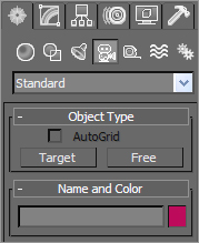
Helpers take care of the unglamorous and thankless jobs in 3ds Max. They help you construct scenes, but they aren’t necessarily part of the scenes. Helpers help you position, measure, and animate a scene’s renderable geometry. Figure 3-19 shows the various helpers you can create.
Figure 3-19: Helpers help you create your scene.

Space Warps
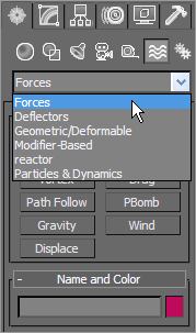
Space warps are objects that deform or animate other objects in your scene. They are known as deformers in other animation packages, such as Maya. You can create ripples and waves and even blow up objects by binding them to Space Warp using the Bind to Space Warp button in the Main toolbar. The drop-down menu shown in Figure 3-20 lists the different space warps available.
Figure 3-20: Creating space warps
Systems
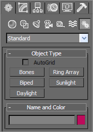
The Systems category holds some advanced functions of 3ds Max. This is where you’ll go to set up Sunlight and Daylight lighting systems, or Bones systems to animate a character or object rig. Figure 3-21 shows the various systems you can create.
Figure 3-21: Systems creation
Modify Panel
The Modify panel, as you saw with the Mobile project, houses all the modifiers you can apply to an object. It also houses a selected object’s Modifier Stack. Using this stack, you can reorder or remove the modifiers for an object, which can be invaluable in creating precisely the right object for your scene.
This panel also allows you to change and animate the parameters for an existing object, such as the radius or length of a cylinder, even after it has been created.
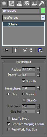
Modifiers are the bread and butter of editing objects in 3ds Max. This form of workflow is terrific because you can stack modifiers on top of each other when creating an object and then go back and edit any of the modifiers in the stack (for the most part) to adjust the object at any point in its creation. This sort of workflow, where any stage of the creation process can be adjusted at any time, is akin to a node-based editing workflow. Figure 3-22 shows the Modify panel for a selected Sphere object.
Almost all the parameters in the Modify panel can be animated. For example, you can create a sphere and animate its radius. Then you can add a Taper modifier and animate the taper amount. You can also go into the sub-object level of a modifier, such as an FFD (free-form deformation), select the control points, and animate the points on the lattice. This can give you layer upon layer of animation. The downside of this is that editing the animation can be a nightmare. For instance, with the FFD, each control point has its own track in the Curve Editor. So, if you have a lattice with 4 × 4 × 4 tracks, you would have to edit 64 potential tracks. You will have a look into tracks and animation in Chapter 8 and in Chapter 9, “Character Studio and IK Animation.”
Figure 3-22: The Modify panel for a sphere
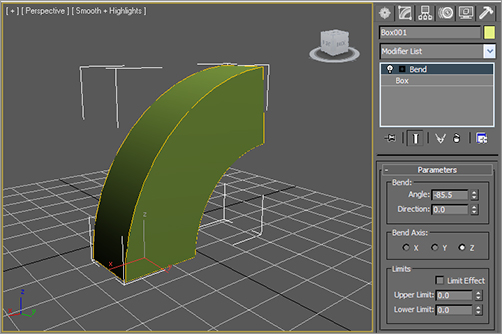
There are two types of modifiers. World Space modifiers attach to an object but affect world space instead of local space. The object must be in proximity to the World Space modifier to be affected. Object Space modifiers affect an object’s geometry in local space. Figure 3-23 shows a Bend modifier applied to a box. The Bend modifier does what it says: It bends the geometry. It is an example of an Object Space modifier because it affects the entire object as one piece.
Figure 3-23: A Bend modifier is applied to a box through the Modify panel.
Hierarchy Panel
The Hierarchy panel is where you create and edit the hierarchies for your objects. As you will see in Chapter 8, creating parent-child relationships through linking allows you to create complex animations—i.e., different rotations on different parts of a mobile. The child objects—or nodes—travel with their parents, but retain the ability to have their own motions once they inherit their parents’ motion(s).
Pivot
In the Hierarchy panel, you can also adjust the position of an object’s pivot point. The pivot point plays a critical role in how an object moves, rotates, and scales. Having control of the pivot point is important to setting up the proper animation for any given object. All objects have a pivot point, which is a center for all transforms. A pivot also defines the transform relationship of a hierarchy, sets the center location of an added modifier, and defines IK (Inverse Kinematics) joint locations.
In the Pivot category of the Hierarchy panel, you can adjust the pivot by moving it, centering it, or aligning it to another object or the world space, as shown in Figure 3-24.
Figure 3-24: Understanding the Hierarchy panel’s Pivot category is a must for proper animation setup.
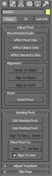
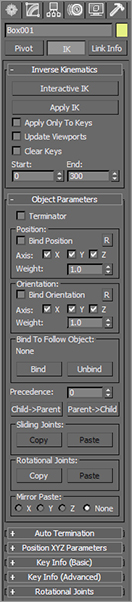
Figure 3-25: The IK category of the Hierarchy panel
IK
Inverse Kinematics (IK) is a method often used in character animation; it provides an easier way to move the parts of a character’s armature by using IK handles to place the limb’s extremities, such as the feet. You simply animate the placement of the feet, and IK solves all the necessary rotations of the leg bones and animates the legs into the proper placement for the feet. The IK category gives you all the tools you need for adjusting hierarchical linkage between objects. The IK panel is shown in Figure 3-25. You will see how IK and bones work in Chapter 9.
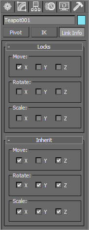
Link Info
Link Info is a great way to set limits for the motions of your objects. The Link Info category allows you to restrict the movement of objects in a hierarchy by limiting from which axes motion is inherited from parents.
Try this exercise:
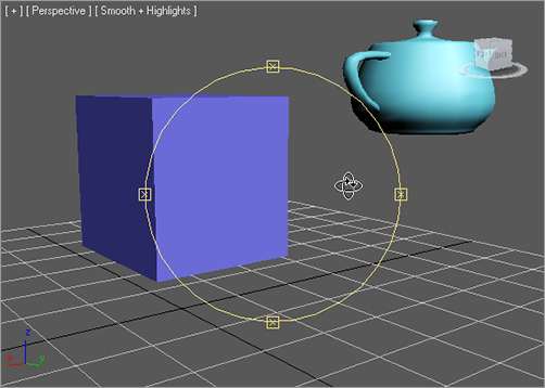
1. In a new scene, create a box of any size and a teapot of similar size. You can find the teapot in the Create panel’s Geometry ⇒ Standard Primitives category.
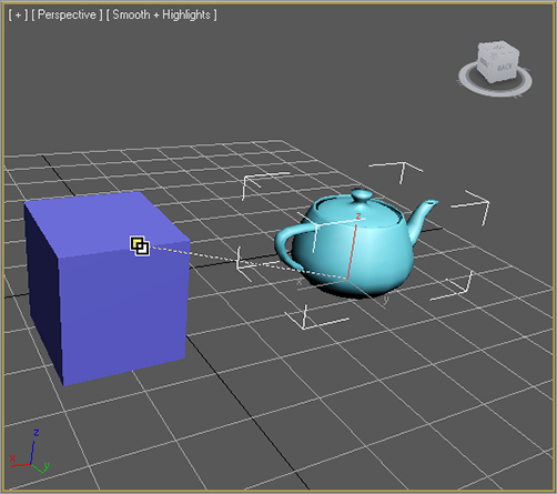
2. Click the Select and Link button (![]() ) on the Main toolbar. Click the teapot then drag the cursor over one of the box’s edges (see Figure 3-26) and then release the mouse button. The teapot is now linked to the box so that the box is the parent of the teapot.
) on the Main toolbar. Click the teapot then drag the cursor over one of the box’s edges (see Figure 3-26) and then release the mouse button. The teapot is now linked to the box so that the box is the parent of the teapot.
Figure 3-26: Linking the teapot to the box
3. Press the W hot key to activate the Move tool. Select and move the box first on the X-axis, then on the Y-axis, and then on the Z-axis. The teapot moves along with the box (assuming the link was created successfully).
4. Select and move the teapot on all three axes as you did the box. The teapot moves in all directions but the box remains stationary.
5. Select the teapot and click on the Hierarchy panel. In the panel, select the Link Info category. Under the Locks rollout, check the box in the Move section for the X-axis. In the Inherit rollout, uncheck the box for Move on the Y-axis, as shown in Figure 3-27.
Figure 3-27: Setting the link parameters
6. Select and move the teapot separately on the three axes. You’ll see that the teapot has been locked on the X-axis and will not move at all on X. This is what a lock does to an object, no matter where it is in a hierarchy.
7. Select the box and move it separately on all three axes. You’ll see that the teapot, except along the Y-axis, moves with the box as it should. The teapot is restricted from inheriting any motion in the Y-axis from the box parent. This is what an Inherit lock does to a child under a moving parent.
Motion Panel
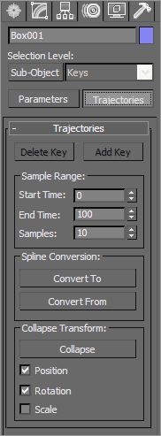
Figure 3-29: The Trajectories category in the Motion panel
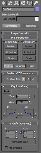
The Motion panel houses all the tools for controlling animated objects using keyframe editing and animation controllers. You will have a chance to play with keyframes and controllers in Chapter 8. The Parameters category allows you to edit keyframes without using the Curve Editor, which is usually the preferred and more powerful way to edit keyframes (Figure 3-28).
Figure 3-28: The Parameters category in the Motion panel
The Trajectories category in the Motion panel (Figure 3-29) allows you to display the path that an object travels in its animation. This way you can actually see the movement an object takes in its animation and adjust it visually to change its course.
Display Panel
The Display panel (Figure 3-30) allows you to choose how an object appears in your viewports. Use the Display panel to Hide/Unhide, Freeze/Unfreeze, and alter display characteristics of objects. This ability is extremely useful when you need to organize your scenes, no matter what their size.
The Hide by Category rollout allows you to turn off the display of certain types of objects to let you focus on other types of objects. For example, if you have a scene replete with geometry objects, but you only need to adjust your lights, you can easily hide your geometry and shapes to better see where your lights are in the scene.
Figure 3-30: The Display panel is important to keeping your scene organized.
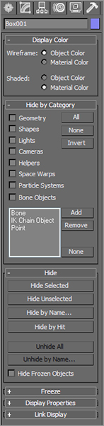
Hiding objects is useful for getting parts of your scene out of the way temporarily. Similarly, freezing objects keeps them visible but prevents you from selecting them. This feature is useful when you still need to reference an object but don’t want to alter it accidentally. When you freeze an object, its display in the viewports turns dark gray by default.
The larger and more complicated your scenes become, the more you can rely on the Display panel to help you with your scene.
You can also use the Layer Manager, which is covered later in this chapter, to help you organize large scenes.
Utilities Panel
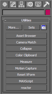
The Utilities panel (Figure 3-31) allows you to access different utility programs, or plug-ins, inside 3ds Max. Some plug-ins are shipped with 3ds Max, and some are third-party applications from various software makers. One such utility is Motion Capture, which allows you to import and work with animation data captured using external devices, such as a joystick or a midi device configured to mimic puppetry animation. These utilities are all advanced and will not be covered in this book. The reactor plug-in is covered in Chapter 12, “Particles and Dynamics.”
Figure 3-31: The Utilities panel
Controls at the Bottom of the UI
Time controls, status information, animation controls, playback controls, and viewport controls are aligned at the bottom edge of the 3ds Max UI. This section covers the icons and functions.
Time Slider and Track Bar
Running across the bottom of the 3ds Max UI are the Time Slider and the track bar, as shown in Figure 3-32.
Figure 3-32: The Time Slider and track bar

The Time Slider allows you to move through any frame in your scene by scrubbing (moving the slider back and forth). By scrubbing, you can also view your animation playback in the viewports. You can move through your animation one frame at a time by clicking on the arrows on either side of the Time Slider or by pressing the < and > keys.
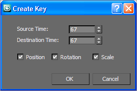
You can also use the Time Slider to animate objects by setting keyframes. With an object selected, a right-click on the Time Slider brings up a Create Key dialog box, which allows you to create transform keyframes for the selected object. Figure 3-33 shows the Create Key dialog box.
Figure 3-33: The Create Key dialog box lets you set a keyframe for a selected object.
The track bar is directly below the Time Slider. The track bar is the timeline that displays the timeline format for your scene. More often than not, this is displayed in frames, with the gap between each tick mark representing frames. On the track bar, you can move and edit your animation properties for the selected object. When a keyframe is present, right-click it to open a pop-up menu where you can delete keyframes, edit individual transform values, and filter the Track Bar display. You will have a chance to explore using these tools in the chapters on animation in this book.
The icon to the left of the track bar is the Open Mini Curve Editor icon. This toggle displays a compact version of the Track View—Curve Editor. The Track View—Curve Editor shows you your scene’s animation as curves that you can edit.
The Status Bar
The status bar in 3ds Max gives you feedback and information as you work in your scene. The status bar (Figure 3-34) runs across about two-thirds of the bottom of the screen. Check it out; you’ll love it.
Figure 3-34: The status bar is full of useful information.
Here are the elements on the status bar.
MAXScript Mini Listener This is a command prompt used for entering and viewing feedback for MAXScript. MAXScript is the scripting language used in 3ds Max to automate actions and customize functions. This line displays a single line of the actual MAXScript Listener window, which gives you easier access in a window to MAXScript.
Status line Displays the number and type of objects selected in your scene.
Lock Selection When your object is selected, Lock Selection lets you lock the object so you won’t inadvertently deselect or select something else in your scene. The icon turns yellow when turned on. The keyboard shortcut for this tool is the spacebar.
Relative/Absolute Transform toggle When you enter values in the Transform Type-In boxes, 3ds Max treats the values as absolute. If you set the toggle to relative, the values you enter will be used to offset the selected object from its current state.
Transform Type-Ins You can enter values in these boxes (delineated as X, Y, and Z values) to transform the selected object, whether it is moving, rotating, or scaling. The Transform Type-Ins allow you to specify exact values for transforms instead of using the gizmo. When nothing is selected and you are moving the cursor around in a viewport, the Transform Type-Ins show the coordinates of your cursor.
Grid setting Shows the size of one grid square on the Home Grid in your viewport. To edit the size of your grid squares, go to the Grid and Snap Settings dialog box. This can be found by right-clicking the Snaps Toggle and clicking the Home Grid tab.
Prompt line Here, 3ds Max displays instructions that prompt you for the next action in a function, such as “Click and drag to select and move objects” when the Move tool is active. The Prompt Line gives you ongoing feedback as you work with a tool. It can be a good place to look when you’re unsure of what to do next. In addition, Tool Tips are displayed here when you mouse over icons and buttons. Mousing around and checking icon names is a good way to become more familiar with the interface.
Adaptive Degradation This toggle helps improve performance in the viewports whenever you transform geometry, change your view, or play back an animation by decreasing the display quality of certain objects temporarily while you are making the transform or change. Only when your 3ds Max scenes become large or your system’s performance is low will this toggle be truly handy. Right-click this icon to access the Adaptive Degradation priority settings.
Add/Edit Time Tag Add/Edit Time Tag is an animation assistant that allows you to set up tags at a certain point in your animation that you can easily jump to by selecting the tag’s name.
Animation Controls
The Animation controls are a selection of icons to the right of the status bar that are used in animation. Figure 3-35 shows the icons.
Figure 3-35: The Animation controls

The functions of the Animation controls are covered in Chapter 8. The rundown on the icons is as follows:
Set Keys Sets a keyframe for the selected object(s) at the current frame for all tracks of the object. A track is a specific translation type (move, rotate, and/or scale, or a parameter) on a specific axis. The keyboard hot key for Set Keys is K.
Auto Key mode Toggles the Keyframing mode on and off. The icon turns red when Auto Key mode is on. Keyframes are automatically created when Auto Key icon is on and objects are transformed or parameters are changed. You don’t need to set a key manually while in the Auto Key mode.
Set Key mode You can create specific keyframes for a selected object by placing the object as you like and then setting a keyframe manually. This Animation mode, along with Key Filters (discussed next), allows you to control exactly which tracks are keyed while you animate. With Set Key mode off, any keys you set will be set for all tracks by default.
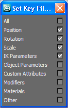
Key Filters Clicking this icon will open the Set Key Filters dialog box shown in Figure 3-36. This is where you can pick the parameter types you want to be keyframed as you animate. This keeps your scene free of extra keyframes you may not need.
Figure 3-36: The Set Key Filters dialog allows you to select the parameter types for which you want keys set.
Selection list Gives you quick access to named selection sets and track sets while you are working in Set Key mode. Lets you easily swap between different selection sets and track sets.
Default In/Out Tangents for New Keys Shortcut for setting up tangent types for keys on curves for animation created with Set Key or Auto Key. This is only for new keyframes. Curves and keyframes are covered in detail in Chapter 8.
Animation Playback Controls
The Animation Playback controls (Figure 3-37) are similar to the ones you would find on a VCR (how old are you?) or DVD player.
Figure 3-37: The Animation Playback controls run your playback.
Go to Start Moves the Time Slider to the first frame in the active time segment.
Previous Frame/Key Moves the Time Slider back one frame or one key, depending on the Key Mode toggle.
Play/Stop Animation Plays your animation in the active viewport. The icon is a flyout ![]() that lets you access another icon (an outline of a play arrow instead of the filled black arrow) to play only the animation of selected objects instead of the entire scene.
that lets you access another icon (an outline of a play arrow instead of the filled black arrow) to play only the animation of selected objects instead of the entire scene.
Go to End Moves the Time Slider to the last frame in the active time segment.
Next Frame/Key Moves the Time Slider forward one frame or one key, depending on the Key Mode Toggle.
Current Frame Also called Go to Frame, this field displays the current frame. It allows you to enter a frame number in the field to jump your Time Slider to that frame. There is also a spinner that you can click/drag to change the frame number.
Key Mode This tool allows you to jump from one keyframe to another. In order for it to work, you must enable it and then use the Previous and Next Key icons to move from one frame to the next. When active, the Key Mode icon turns dark, and the Previous Key and Next Key icons appear as shown in Figure 3-38.
Figure 3-38: Stepping keys instead of frames
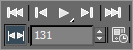
Figure 3-39: The Time Configuration dialog box
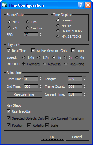
Time Configuration A dialog box (Figure 3-39) where you control frame rates, time display, playback, and animation. You can use this to scale your animation length so it goes faster or slower, or to add more frames to the start or end of your animation. This is covered further in Chapter 8.
Viewport Navigation Controls
The tools for viewport navigation are extensive, and many of the icons have nested flyouts that give access to multiple tools. The available tools change depending on the type of viewport you have selected, such as Orthographic, User (a 3D view that is created when an orthographic view is rotated), Perspective, Camera, or Light. Working with the UI is the best way to learn what tools are associated with each viewport.
When several of the navigation tools are is selected, they turn dark and remain selected until you choose another tool, right-click in a viewport, or press Esc.
Viewports are used for orthographic and perspective views, and also for views through cameras and lights. By setting a viewport to a view from a camera or light, you can easily position the camera or light exactly as you need it using the Viewport Navigation controls, working interactively as you watch the result in that viewport. (We will experiment with cameras and lights in later chapters in this book.)
The Navigation controls, as they appear when the Perspective viewport is active, are shown in Figure 3-40
Figure 3-40:The Viewport Navigation icons for a Perspective viewport
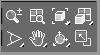
Figure 3-41 shows how the icons appear while an Orthographic viewport is active.
Figure 3-41: The Viewport Navigation icons for an Orthographic viewport

Figures 3-42 and 3-43 show the default icons for a Light viewport and a Camera viewport, respectively.
Figure 3-42: The Viewport Navigation icons for a Light viewport

Figure 3-43: The Viewport Navigation icons for a Camera viewport
In the following tables, all of the Viewport Navigation icons are laid out and briefly explained. The 3ds Max screen has a lot of icons, but experience will help you make sense of things very quickly. Take a look at these icons and click around to get a feel for how they work.
Create a few objects to have something to look at in your viewports, or open the Mobile exercise’s scene file. Spend some time poking around the viewports and looking at things. Use the Viewport Navigation controls and their key/mouse combinations to get a bit more used to navigating.
The key to getting good at navigating 3ds Max, or any other 3d package, is to work on projects and get things done. You will gain the skills you need as you work toward a goal. As you will see, the exercises in the rest of this book will let you flex your muscles and give you a chance to become comfortable with 3ds Max.
The individual icons are explained in the following tables. Refer back to Figures 3.40 through 3.43 to see the icons’ locations in the UI.
Tools Available in All Viewports
Keep in mind that some of the following icons are nested icons beneath flyouts; to reveal them you will need to click and hold the flyout icon. An example of a flyout for the Viewport Navigation controls is shown here:
| Icon | Name | Function |
|
|
Zoom Extents All | Lets you zoom in your scene in all four viewports. The keyboard shortcut for this tool is Z. |
|
|
Zoom Extents All Selected | Works like Zoom Extents All for objects that you have selected. |
|
|
Maximize Viewport Toggle | Toggles between Normal and Full Screen viewport sizing. The keyboard shortcut is Alt+W. |
|
|
Pan View | Lets you move the view of the current viewport up, down, and side to side. The shortcut is Ctrl+P; you can also click/drag the middle mouse button. For Camera and Light viewports, this is the Truck Camera/Light that moves the respective object parallel to the viewport. |
Tools Available in Perspective and Orthographic Viewports
These icons (refer back to Figures 3-40 and 3-41) appear available in the Perspective and Orthographic viewports. Keep in mind that some of the following icons are nested beneath flyouts.
| Icon | Name | Function |
|
|
Zoom | Zoom magnifies the objects in your viewport by moving the view in and out of 3D space in the scene. If your mouse has a scroll wheel, you can use it as a Zoom tool by placing the cursor in the selected viewport and rolling the scroll wheel to zoom in and out. |
|
|
Zoom All | Works like Zoom but lets you zoom all viewports at once. |
|
|
Zoom Extents | This flyout icon works like a Fit to Window function because it zooms all objects in your scene into the viewport. It works for only Orthographic and Perspective viewports. |
|
|
Zoom Extents Selected | This flyout icon is nested with Zoom Extents. It works like the Zoom Extents tool for selected objects only. |
|
|
Field-of-View (FOV) | This flyout icon, nested with Zoom Region, is also available in Camera viewports. FOV changes the amount of the scene that you can see in the viewport by adjusting the field of view. It increases the viewable area by increasing the angle viewed, like a camera lens. |
|
|
Zoom Region | This flyout icon nested with Field-of-View allows you to drag a rectangle marquee around the area you want to zoom in on. This tool is available only in Orthographic/User and Perspective viewports. |
|
|
Walkthrough | This flyout icon is nested with Pan View. This very cool tool lets you move through a viewport by pressing the arrow keys. It is similar to the Pan View tool, but you use the arrow keys instead of the mouse for navigation. When you enter the Walkthrough Navigation mode, the pointer changes to a hollow circle that shows a directional arrow while you are pressing one of the arrow keys. Walkthrough is available only for Perspective and Camera viewports. |
|
|
Orbit | This flyout Icon is nested with Orbit Selected and Orbit Sub-Object. Orbit lets you rotate a viewport by clicking and dragging a series of handles on the gizmo. It uses the viewport center as the center for its rotation. The shortcut is Ctrl+R and you have the same functionality, without the gizmo, using Alt+MM. Figure 3-44 shows the Orbit gizmo in action. |
|
|
Orbit Selected | This tool works like Orbit but uses the selected object as the center for rotation. The object remains in the same position as the viewport rotates around it. |
|
|
Orbit SubObject | This tool works similarly to Orbit Selected, but it rotates about the current sub-object selection. |
Figure 3-44: The Orbit gizmo
Camera Viewport Controls
A camera view shows your scene through the lens of a virtual camera. The specific tools available will change depending on whether you are using a Free or Target camera. (Cameras are covered in Chapter 11.)
Again, use this section as a reference, and click along with the descriptions. You don’t need to memorize it all or understand everything at once. You can come back to this chapter when you need to look up something.
To access these navigation tools, you will need to create a camera and switch a viewport to its view. To create a camera, follow these steps in a new scene or a current scene:
1. Choose Create ⇒ Cameras ⇒ Free Camera, and click in one of your viewports to place the camera. You may also click in the Create panel under the Cameras category and click the Free icon. Figure 3-45 shows a camera placed in the scene.
Figure 3-45: A camera placed in a scene
2. Click the Select Object tool to end the active tool.
3. Click a viewport name in the upper-left corner of the viewport, and select Cameras ⇒ Camera001, as shown in Figure 3-46. This will change the viewport to the camera’s view. You will now be able to access the Camera Viewport Navigation tools shown in the following table.
Figure 3-46: Set your viewport to the new camera.

Now that you have created a Free camera in your scene, click the following icons as you explore to see how they’ll help you navigate in a Camera viewport. To use these tools, select them and then click and drag in the Camera viewport. Some of these navigation icons apply to a Target camera only, and several of these icons are flyouts nested with other icons:
| Icon | Name | Function |
|
|
Dolly Camera | Moves the camera object toward and away from the object at which it is pointing. |
|
|
Dolly Target | Moves the camera’s target toward and away from the object. This may not show any changes unless you use other camera tools, such as Orbit. |
|
|
Dolly Camera + Target | Moves the camera and target to and from the object at which it is pointing. This is available only if the camera has a target. |
|
|
Perspective | Adjusts Field-of-View (FOV) and lens length. |
|
|
Roll Camera | Rolls the camera around the line of sight for a Target camera or (if it is a Free camera) around the local Z-axis. |
|
|
Truck Camera | Moves the camera from side to side, parallel to your scene. |
|
|
Orbit Camera | Rotates the camera around the target object. This is on the flyout with the Pan Camera icon. |
|
|
Pan Camera | Rotates the target around the camera. This is on the flyout with the Orbit Camera icon. |
Light Viewport Controls
This set of tools shows your scene through the perspective of a light. This may seem a bit unusual, but it can be very useful for exact positioning of your lights. Some tools for the light objects have the same names (Dolly, Roll, Truck, Orbit, and Pan) and are used the same way as the Camera navigation tools. Therefore, their icons are not repeated here. However, the Light viewport controls that are specific to lights are listed.
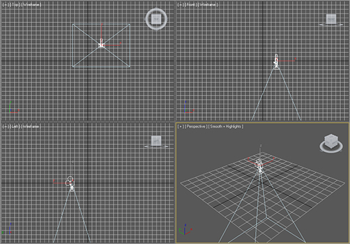
You will need to create a light in your scene to access these icons in the Viewport Controls section of the UI. To create a light in the scene, follow these steps:
1. Choose Create ⇒ Lights ⇒ Standard Lights ⇒ Free Spotlight and click in one of your viewports to place the light. You may also click the Create panel, then, under the Lights category, choose Standard from the drop-down list and click the Free Spot icon. Figure 3-47 shows a light placed in the scene.
Figure 3-47: A Free spotlight

2. Click the Select Object tool to end the active tool.
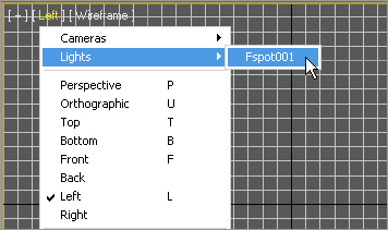
3. Click a viewport name in the upper-left corner of the viewport, and select Lights ⇒ Fspot001, as shown in Figure 3-48. This will change the viewport to the light’s view. You will now be able to access the Light Viewport Navigation tools shown in the following table:
| Icon | Name | Function |
|
|
Light Hotspot | Lets you adjust the angle of the light’s hotspot, which is the brightest part of the pool of light. |
|
|
Light Falloff | Lets you adjust the angle of the light’s falloff, which is the light fading to the edges of the pool of light. |
Figure 3-48: Set your viewport to the new light.
Light viewport controls help you place your lights just the way you want them. (You’ll get more hands-on experience with lights in Chapter 10, “3ds Max Lighting.”)
If you are getting sick of looking at icons, remember that nearly all viewport navigation tasks can be performed using the keyboard shortcuts and the mouse buttons. This rich set of navigation tools gives you many options for moving around in 3D space, but you needn’t really worry about any of them until you are comfortable just getting around—and by now this should be coming easier to you.
Navigating Viewports
The easiest way to navigate the viewports is to use the keyboard/mouse combinations available in 3ds Max. Here is a review of these keyboard/mouse actions.
Pan Panning a viewport will “slide” the view around the screen. MM+click in the viewport and drag the mouse to move the view.
Zoom Zooming will move your view closer to or farther away from your objects. To zoom, use the scroll wheel or press Ctrl+Alt and MM+click in your viewport, and then drag the mouse up or down to zoom in or out, respectively.
Orbit and Orbit Selected Orbit and Orbit Selected let you rotate your view around your objects. To use either of the two Orbit tools, press Alt and MM+click and drag in the viewport. Use Shift+Alt+ MM for constrained rotation. By default, 3ds Max will rotate about the center of the viewport to change your perspective. However, if an object is selected, 3ds Max will revert to Orbit Selected, which will rotate about the center of the selected object instead of the center of the viewport. This way the object remains in the same position as the viewport rotates around the object.
Viewports are where 3D space is simulated. Viewports in 3ds Max are initially set up with four equally sized views (Top, Front, Left, and Perspective viewports). One will have a yellow highlighted border, which shows that this viewport is the selected view. You can activate a view by working in it or by right-clicking in it. (Be careful about left-clicking, because if something is selected, it will be deselected when left-clicked.)
Figure 3-49: The Layout tab of the Viewport Configuration dialog box allows you to quickly change your viewport layouts.

Figure 3-50: The World Space tripod in the Perspective viewport

You can also resize your viewports by centering the pointer over the splitter bars that separate the views. The pointer will change to a two or four-sided arrow, and you can click/drag the viewports to the size desired. To switch the viewport layout back to the default, right-click over the center splitter bars the click “Reset Layout” on the pop-up menu to go back to the default.
Let’s not forget the Maximize Viewport toggle in the navigation area (its hot key is Alt+W). This will change the equally sized views into one full-screen view of the active viewport.
One way to change the default look of your viewports is to use the Viewport Configuration dialog box. You can find it by choosing Views ⇒ Viewport Configuration ⇒ Layout tab and clicking the desired layout, as shown in Figure 3-49.
In the lower-left corner of each viewport, the axes are displayed as part of the World Space tripod. The axes are always displayed in red, green, and blue format to represent the X-, Y-, and Z-axes respectively, as shown in the Perspective viewport (see Figure 3-50). You have seen this familiar color scheme at work in the gizmos as well.
You’ve undoubtedly noticed the Home Grid in your viewports by now. This grid is a ground plane that centers around the Origin (0, 0, 0). Right-click on the Snaps toggle, then click the Home Grid tab to access the parameters that define the spacing of the Home Grid, as shown in Figure 3-51.
Figure 3-51: The Home Grid tab where the Home Grid parameters are set
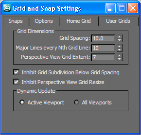
The Home Grid is a helper for the construction of objects. When you create a new object, it is placed on the grid. The Home Grid’s defaults can be edited for more effective scene creation, and they can be turned on and off in the current viewport by pressing the G key.
The grid displays the units of your scene. The default is set up as Max Units, where one unit equals 1 inch. Each grid division is 10 units. The best approach is to choose a grid spacing that matches your unit of measurement. For example, if you are using centimeters, make one grid square equal 1 centimeter.
Changing Viewport Views
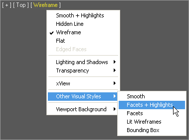
As you saw earlier, the viewports are flexible and can be changed to different rendering modes by clicking on the viewport name and choosing the new viewport rendering mode from the menu (Figure 3-52).
Figure 3-52: Selecting the viewport rendering mode
This lets you change which view you have in a viewport. You can also use keyboard shortcuts to access any of the viewports. In an active viewport, press the hot key for the desired view. Hot keys are listed in this table:
| Hotkey | View |
| T | Top |
| B | Bottom |
| F | Front |
| L | Left |
| C | Camera |
| P | Perspective |
| U | User or Axonometric—a 3D view without perspective |
These keys are extremely helpful when one viewport is maximized and you need to access different views quickly. For scenes that have more than one camera, press the C key to bring up a pop-up menu from which you can select the camera. With so many ways to change viewport views, you’ll be able to find the way that works best for your workflow.
Because the R shortcut enables the Select and Scale tool, there is no keyboard shortcut for the Right viewport.
Viewport Rendering Modes
Viewports let you view your scene in a few different ways. For example, in the Mobile exercise, you saw how you can switch between Wireframe and Smooth + Highlights Shaded views. How you view objects in a viewport is referred to as viewport rendering. Again, you can access a different viewport rendering method by clicking the viewport’s name. Depending on the size of your scene, your viewport may be more responsive and have a less-taxing rendering display level than the one shown here.
Each of the viewport rendering modes has specific properties.
Smooth + Highlights Displays scene objects with smooth shading and specular highlights from the scene lights (see Figure 3-53). This gives the best feedback for your objects.
Smooth Displays objects with no highlights and only smooth shading, as shown in Figure 3-54.
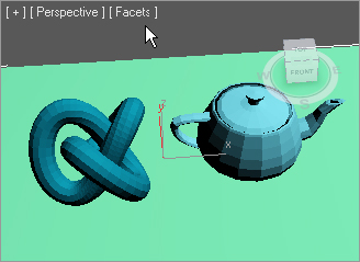
Facets + Highlights Displays scene objects with flat shading and displays specular highlights (see Figure 3-55). This is a fast way to see your solid objects with highlights when Smooth+ Highlights is too taxing with heavy scenes.
Facets Displays polygons as flat surfaces that are shaded, but includes no smoothing or scene highlights, as shown in Figure 3-56.
Figure 3-53: A viewport in Smooth + Highlights rendering mode
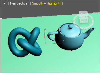
Figure 3-54: A viewport in Smooth rendering mode

Figure 3-55: A viewport in Facets + Highlights rendering mode
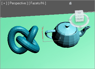
Figure 3-56: A viewport in Facets rendering mode
Flat Displays each polygon in its raw diffuse color, disregarding any scene lighting or light sources (see Figure 3-57). This viewing method is useful when you need to see each polygon rather than to see the polygons’ shading.
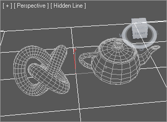
Hidden Line A Wireframe mode that allows you to use the Wireframe mode without seeing through every object (see Figure 3-58). In this display mode only, the wireframe color is determined by choosing Customize ⇒ Customize User Interface in the Colors tab under Elements ⇒ Viewports and selecting Hidden Line Unselected rather than the object or material color.
Figure 3-57: A viewport in Flat rendering mode
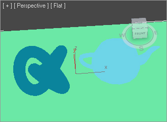
Figure 3-58: A viewport in Hidden Line rendering mode
Lit Wireframes Displays objects as their wireframes, with a flat shading for a sense of lighting, as shown in Figure 3-59.
Wireframe Draws objects as wireframes only, as shown in Figure 3-60. This is the fastest viewing method that still lets you see an object’s shape.
Figure 3-59: A viewport in Lit Wireframes rendering mode
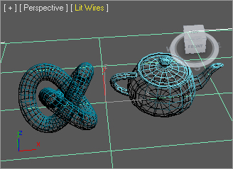
Figure 3-60: A viewport in Wireframe rendering mode

Bounding Box Displays objects as bounding boxes (see Figure 3-61). Bounding boxes are approximations of the volume a shape occupies. No shading is applied.
3ds Max 2011 will automatically degrade the display of certain objects variably (such as by using bounding boxes) when the geometry in a complex scene is too much for the display to handle when the viewport is being panned or zoomed. You probably will not encounter this feature, called Adaptive Degradation, until you begin dealing  with very large scenes. You can disable Adaptive Degradation by pressing the keyboard shortcut O.
Edged Faces Edged Faces draws the wireframe of an object back onto its shape when it is displayed in one of the shaded modes (Smooth, Smooth + Highlights, Facets + Highlights, or Facets). Edged Faces lets you see the wireframe lines and faces of an object for easier editing, while still seeing it shaded. Figure 3-62 shows a viewport in Smooth + Highlights mode with Edged Faces turned on.
Figure 3-61: A viewport in Bounding Box rendering mode
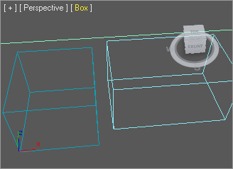
Figure 3-62: A viewport in Smooth + Highlights rendering mode with Edged Faces

Setting the viewport rendering modes will help you with larger scenes. More often than not, viewing your scenes with the Smooth + Highlights mode will give you the best feedback. With the Adaptive Degradation feature, you won’t need to worry about which rendering level you choose. The levels are designed to automatically adapt when your system’s responsiveness is slow because of a large scene.
Gizmos
Using gizmos is a fast and effective way to transform your objects with interactive feedback. As you saw in the Mobile exercise in the previous chapter, gizmos let you manipulate objects in your viewports interactively to transform them—i.e., move, rotate, and/or scale. Coordinate Display boxes at the bottom of the screen display coordinate or angular or percentage information on the position/rotation/scale of your object as you transform it. The gizmos appear in the viewport on the selected object at their pivot point as soon as you invoke one of the transformation tools.
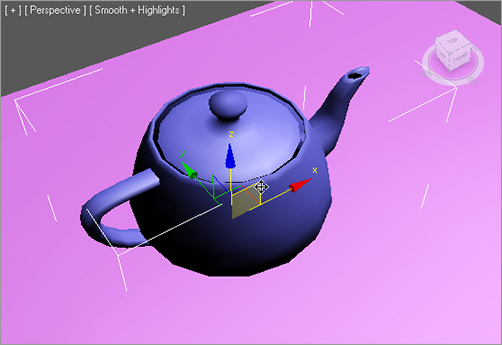
After you invoke the Move tool by pressing W (or accessing it through the Main toolbar), your gizmo should look like Figure 3-63.
Dragging the XYZ-axis handles moves an object on one specific axis. You can also click on the plane handle, the box between two axes, to move the object in that plane. Moving an object in the XZ plane is shown in Figure 3-64.
If you invoke the Rotate tool by pressing E, your gizmo will turn into three circles, as shown in Figure 3-65. You can click on one of the circles to rotate the object on the axis only, or you can click anywhere between the circles to freely rotate the selected object in all three axes. Click and drag the gray outer circle to rotate the object parallel with the viewport.
Invoke the Scale tool by pressing the R key, and your gizmo will turn into a triangle, as shown in Figure 3-66.
Figure 3-63: The Move gizmo

Figure 3-64: Moving the object using the XZ plane handle
Clicking and dragging anywhere inside the yellow triangle will scale the object uniformly on all three axes. By selecting the red, green, or blue handles for the appropriate axis, you can scale along one axis only. You can also scale an object on a plane between two axes by selecting the side of the yellow triangle between two axes as shown in Figure 3-67.
Keep in mind that the gizmos appear at an object’s pivot point; therefore, if there is an object where you have relocated the pivot point away from the object itself, the gizmo will appear there and not on the object itself. Figure 3-68 shows the Move gizmo when the teapot’s pivot is to the right of the object.
Figure 3-65: The Rotate gizmo
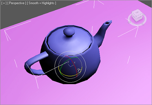
Figure 3-66: The Scale gizmo
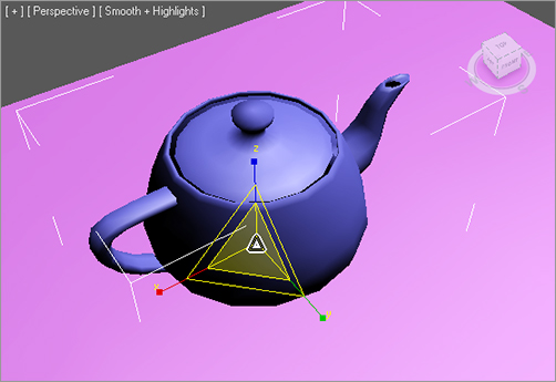
Figure 3-67: Scale along only two axes.
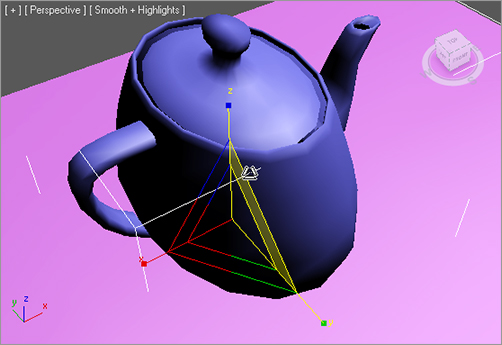
Figure 3-68: The gizmo is located at the pivot point.

Figure 3-69: The Transform Type-Ins
When transforming your objects, keep an eye on the Transform Type-Ins at the bottom of the UI (see Figure 3-69). These will reflect the movement distance, rotation angle, or scale percentage for the current transform. As the name indicates, you can also enter values in the fields and the object is transformed accordingly.
3ds Max has a few ways to organize and manage your scene elements to make you work easier. These tools include the Layer Manager, the Schematic View, two Material Editors, and the Curve Editor/Dope Sheet. The Layer Manager works with objects to organize them in layers. The Schematic View allows you to view, manage, and edit your scene’s hierarchies. The Layer Manager and Schematic View windows are outlined for you here, and they are used extensively throughout this book.
The Material Editors allows you to manage your scene’s materials and textures. The Material Editors are covered in Chapter 7, “Materials and Mapping.” The Curve Editor manages the animation in your scene by giving you access to animation curves. The Dope Sheet manages the animation in your scene by giving you access to animation ranges or sets of keys. The Curve Editor is covered in Chapter 8, and the Dope Sheet is covered in Chapter 9.
Layer Manager
The Layer Manager (Figure 3-70) can be accessed through the Manage Layers icon on the Main toolbar (![]() ).
).
Figure 3-70: The Layer Manager
Layers can be used to organize scene objects. In 3ds Max, layers are organized similarly to Photoshop layers; you can organize different elements of an image in separate layers. Layers are mainly used to control object visibility, default color, selecting, freezing, and hiding. All of these functions help you organize your scene and make object management easier. You will use the Layer Manager in future exercises in this book.
The icons across the top of the Layer Manager are explained here.
Create New Layer Creates a new layer when you have objects selected in your scene. The selected objects are assigned to the new layer.
Delete Highlighted Empty Layers Deletes selected layers if they are empty.
Add Selected Objects to Highlighted Layer Moves currently selected objects into the selected layer.
Select Highlighted Objects Selects all highlighted objects, as well as all objects contained in any highlighted layers.
Highlight Selected Objects’ Layers Highlights layers containing the currently selected objects and automatically scrolls so that highlighted layers are visible in the Layer Manager.
Hide/Unhide All Layers Enables the display of all layers.
Freeze/Unfreeze All Layers Enables the frozen state of all layers.
The columns in the Layer Manager window itself are the following:
Layers Displays the names of the layers/objects. To select or rename a layer, click its name. To display object or layer properties, click the object icon to open the Object Properties dialog box for all highlighted objects.
Current Layer toggle The unlabeled column to the right of the Layers column indicates the current layer. The check mark next to a layer means it is selected and current. This feature lets you make a different layer current.
Hide Hides and unhides layers. When a layer is hidden, its objects are not visible in the viewport.
Freeze Freezes layers. Objects on frozen layers cannot be selected.
Render When this feature is enabled, objects appear in the rendered scene. Nonrendering objects won’t cast shadows or affect the visual component of the rendered scene.
Color Changes the default color on highlighted objects.
Radiosity When this feature is enabled, objects are included in the radiosity solution.
Using the Layer Manager
The Layer Manager can be extremely useful for organizing and managing your scene objects. You will use the Layer Manager throughout the rest of this book. Let’s take a quick look at how the Layer Manager can help you with a scene.
1. Open a new scene and create four new objects: a box, a sphere, a cone, and a torus (see Figure 3-71).
Figure 3-71: The Layer Manager
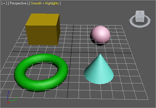
2. Open the Layer Manager by clicking the Manage Layers icon (![]() ) in the Main toolbar. Click the Create New Layer icon (
) in the Main toolbar. Click the Create New Layer icon (![]() ) twice to create two new layers.
) twice to create two new layers.
To select more than one object in a viewport, press the Ctrl key as you click on additional objects to add to your selection. Many applications use the Shift key to add to a selection; however, 3ds Max uses Ctrl.
Figure 3-72: Adding an object to the selected layer
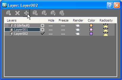
3. In the viewport, select the box and the sphere and assign them to Layer001 by selecting Layer001 and clicking the Add Selected Objects to Highlighted Layer icon (![]() ) in the Layer Manager, as shown in Figure 3-72.
) in the Layer Manager, as shown in Figure 3-72.
4. Following the procedures in step 3, assign the cone to Layer002.
5. Select Layer001 and click in the Freeze column. The sphere and box will turn gray in the viewport and you will no longer be able to select them.
6. Click in the Hide column for Layer002, and the cone will disappear from the viewports (see Figure 3-73).
Experiment with toggling Hide and Freeze for the objects or the layers so that you can see how your scene reacts when they are on and off.
Figure 3-73: Freezing and Hiding layers
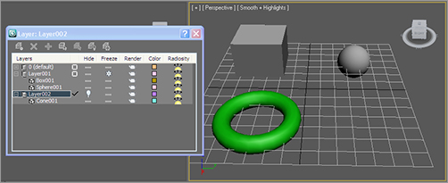
Schematic View
The Schematic View is another way to organize and manage your scene, particularly object hierarchies. This dialog box displays the objects in your scene in a flowchart scheme, allowing you to see how objects are linked or grouped together. Parents connect down the flowchart to their children. This method of viewing hierarchies is powerful, because you get an immediate visualization of how the objects in your scene work and relate to each other. Figure 3-74 shows a scene in the Schematic View.
A scene can become so complicated that trying to select one object is impossible. The Schematic View makes editing character rigs easier, allowing you to view, create, and edit links between objects. The Schematic View simplifies the selection process by clearly displaying every object in the scene as a box with the object’s name displayed in it. You can use the middle mouse button to pan in the Schematic View, or you can use any of the familiar navigation icons found in the lower right-hand corner of the window, as shown in Figure 3-74.
Figure 3-74: A scene broken down in the Schematic View immediately tells you how the objects are organized.
When the Modify panel is open and you select any object in the Schematic View, its parameter automatically appears in the Modify panel for easy editing. Because objects can have different states of being, different conventions are used to indicate an object’s current state in the scene, with the most important states listed here:
Red border The object is animated.
White fill The object is currently selected in the Schematic View window.
White border The object is currently selected in a viewport.
Collapse Selected button Used to simplify a view. Pressing the Collapse Selected button (![]() ) collapses each node and its dependent child nodes up to the selected parent, putting everything into one node for simpler display. This is useful for large characters and long hierarchy chains because you don’t have to see all the child nodes in a large scene. This does not remove the hierarchy; it only affects the display.
) collapses each node and its dependent child nodes up to the selected parent, putting everything into one node for simpler display. This is useful for large characters and long hierarchy chains because you don’t have to see all the child nodes in a large scene. This does not remove the hierarchy; it only affects the display.
Expand Selected button Used to gain more information about a hierarchy of objects. Clicking the Expand Selected button (![]() ) expands the next child down from that node to show you its immediate child node(s).
) expands the next child down from that node to show you its immediate child node(s).
In Figure 3-74, you can see how the Turret node is the highest parent for the hierarchy; the second row of bars hangs from the PivotBottom node as its children.
The toolbar across the top of the Schematic View is used for editing hierarchies in your scene. We will experiment with reordering the Mobile hierarchy in the Schematic View in just a moment. First, let’s look at the tools as called out in Figure 3-74.
Display floater Enables the Display floater window, which gives you access to display toggles for certain object types in the Schematic View.
Select Allows you to select objects in the Schematic View. When you select an object in a viewport, its node in the Schematic View will be outlined in white. However, it will not necessarily be selected in the Schematic View. If you want to be able to select an object in either window once and have it selected in both the Schematic View and the viewports, choose Select ⇒ Sync Selection in the Schematic View window.
Connect To create links in the Schematic View, just as you created a link between objects earlier in this chapter, click the child object and drag it to the desired parent.
Unlink Selected To break links between objects, click the child to unlink and then click this icon.
Delete Objects Deletes the selected object(s) from the scene. If you make a mistake, you can press the Undo icon in the Main toolbar or press Ctrl+Z to get the object(s) back.
Hierarchy Mode Lays out the Schematic View as an outline view, as shown in Figure 3-75.
Figure 3-75: The Schematic View in Hierarchy mode

References Mode Lays out the view in the Schematic View, as shown earlier in Figure 3-74. This view is good for viewing object relationships and materials.
Always Arrange The Schematic View will keep the node display rigid. As you see in the References Mode, you will not be able to freely move nodes around. Turning off the Always Arrange mode allows you to arrange the nodes any way you want, as shown in Figure 3-76.
Figure 3-76: Turning off Always Arrange allows you to adjust the node locations.
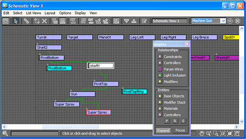
The next group of icons—Arrange Children, Arrange Selected, Free All, and Free Selected—all have to do with automatically arranging nodes when you turn off Always Arrange.
Move Children When you click and drag a node, all of its child nodes will follow it when this mode is enabled.
Expand/Collapse Selected Used to reveal or hide the child nodes of the selected node.
Preferences Opens the Schematic View Preferences dialog box, where you can filter certain object types (such as lights, cameras, objects, etc.) from displaying in the Schematic View.
Figure 3-77: Accessing a saved Schematic View
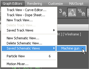
Name field Lets you save certain views to recall later for easy access. When you have a heavy scene, with tons of nodes to view, getting to the right place in a complicated hierarchy can take some time. When you type a name for your current view into this text box, 3ds Max will save the view for you. To access that particular view again, in the main menu bar, select Graph Editors ⇒ Saved Schematic Views ⇒ Schematic View Name. See Figure 3-77.
Bookmark Lets you define a selection of nodes in the Schematic View with bookmarks that you can later return to easily.
Using the Schematic View with the Mobile
Let’s take a look at the Schematic View in action, and have another whack at the Mobile scene’s hierarchy.
You can start with your own Mobile scene file, or load the scene Mobile Hierarchies.max from the Scenes folder in the Mobile project on this book’s companion web page. Just follow these steps:
1. With your Mobile scene loaded, open the Schematic View, as shown in Figure 3-78, by choosing Graph Editors (![]() ) in the Main toolbar.
) in the Main toolbar.
2. Link the Star001 object to the Circle001 object. To do this, click the Connect button and then select the Star001 node and drag it to the Circle001 node, as shown in Figure 3-79. The location of the Star001 node has been moved for clarity.
Figure 3-78: The Schematic View for the Mobile scene

3. When you release the mouse button, notice that the Star001 node is linked to the Circle001 node. Click the Always Arrange button in the Schematic View toolbar, if necessary, and the Star001 node will relocate below the Circle001 node, as shown in Figure 3-80.
Figure 3-79: Connecting the star to the circle
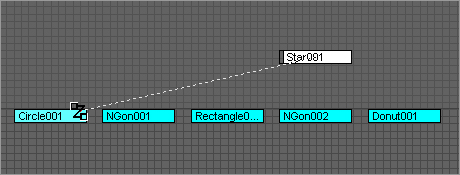
Figure 3-80: The star is linked under the circle.

You can see how easy it is to restructure your scene hierarchies using the Schematic View. All the controls for viewing and arranging nodes might be a bit much for one window. You probably won’t need half those icons, but knowing how to use the Schematic View is important. It is an important tool in organizing and setting up your scenes for animation. You will continue to use the Schematic View throughout this book.
The Scene Explorer dialog (Figure 3-81) is accessed through Tools ⇒ New Scene Explorer and is an expanded version of the dialog opened with the Select by Name icon in the Main toolbar, discussed earlier in the chapter. Scene Explorer allows you to view the objects in your scene by name, as well as sort or filter them by type, view and edit their hierarchies, and generally manage the objects in your scene. Through the Scene Explorer you can rename, delete, hide, freeze, and edit some object properties en masse.
Two primary uses of the Scene Explorer are to select objects and edit their hierarchies. To select objects in your scene in Scene Explorer, enable Sync Selection by clicking its icon along the bottom of the Scene Explorer dialog box (see Figure 3-81). While it is enabled, if you select an object in your scene through a viewport, it is simultaneously selected in the Scene Explorer and vice versa.
You can link and unlink objects to edit hierarchies as well. If you drag an object’s icon onto another object in the Scene Explorer dialog until you see a yellow arrow to the left of the target object, the dragged object will become a child of the target object. Figure 3-82 shows the Leg Right object being linked to the Target object. To unlink an object, drag its icon from the target object in the Scene Explorer to the Scene Root node at the top of the list.
Figure 3-81: The Scene Explorer dialog box
Figure 3-82: Linking objects in the Scene Explorer dialog box
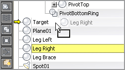
You can have as many Scene Explorer windows open as you like, because they persist in your scene as you work. You can toggle between different views of the Scene Explorer that you have opened previously through the window’s View Explorer pull-down menu.
The Quad Menu and the Caddy Interface
The more you can keep your eyes on the viewports, the more productive your time will be. Every time you have to move your attention to a menu, toolbar, or panel, and then back to your scene, a little more of your time is gone. 3ds Max’s Quad menu and Caddy interface are part of the “on canvas” toolset designed to maximize your efficiency by minimizing the time spent looking outside of the viewports.
The Quad Menu
The Quad menu, as the name implies, displays up to four menus, depending on the type of object(s) that are currently selected. When a primitive object, such as a sphere or box, is selected, right-clicking opens two panels of the quad menu, Display and Transform, as shown in Figure 3-83.
Figure 3-83: The two-panel display of the Quad menu

In the Display menu, you can define how the selected object is displayed in the scene. Objects can be hidden or unhidden by name or by selection, or frozen by selection only. You can only unfreeze all frozen objects at one time using the Quad menu. The Transform panel provides quick access to the transforms (Move, Rotate, and Scale) as well as tools to select and clone objects and to access three of the graph editors. Clicking the Object Properties option opens the Object Properties dialog box (see Figure 3-84), where all of an object’s properties can be edited. The Convert To option in the Quad menu expands to display a list of object types to which the current selection can be converted.
Right-clicking when a mesh object is selected brings up two additional panels, Tools 1 and Tools 2, as shown in Figure 3-85. The Tools 1 panel contains access to the sub-object levels for the mesh as well as some of the basic mesh editing tools. The Tools 2 quad only contains the Create option for creating sub-objects for the selected mesh. Meshes and sub-objects are covered in Chapter 4, “Modeling in 3ds Max: Part I.”
As you’ve seen, the Quad menu adapts itself to the object that is selected. Sub-object selections are no exception, as you can see in Figure 3-86, which displays the quad menu when a sub-object selection is current. As you can see when compared to Figure 3-85, both the Tools 1 and Tools 2 panels are expanded to include additional, sub-object–related tools.
Figure 3-84: The Object Properties dialog box

Figure 3-85: The Quad menu when a mesh is selected
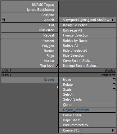
Figure 3-86: The Quad menu when a sub-object is selected
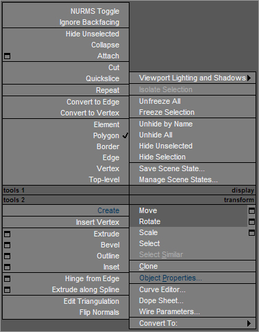
Quad menus are efficient, easy to open, and should be a significant component of your 3ds Max workflow.
The Caddy Interface
Like the Quad menu, the new caddy interface is designed to keep your eyes in the viewports while providing context-sensitive tools. The caddies replace the Settings dialog boxes available in previous versions of 3ds Max. Depending on the tool, clicking the Settings button (![]() ) may display the tool-specific caddy directly over the selected objects or sub-objects. Figure 3-87 shows the Extrude Polygons caddy. Each tool’s caddy is slightly different and may include more than one parameter.
) may display the tool-specific caddy directly over the selected objects or sub-objects. Figure 3-87 shows the Extrude Polygons caddy. Each tool’s caddy is slightly different and may include more than one parameter.
Figure 3-87: The Extrude Polygons caddy

Pausing the cursor over any of the highlighted features changes the caddy title to reflect the name of that feature. Clicking a feature with a down arrow opens a drop-down menu where you can choose an option. There are three methods for executing the changes in a caddy: OK, Apply and Continue, and Cancel. OK applies the parameter values set then closes the caddy. Apply and Continue applies the parameter values but keeps the caddy open. Cancel terminates the command without applying the parameter values and closes the caddy.
Wow! That was a lot of information. You’ve learned how to navigate the menus, toolbars, icons, panels, and dialog boxes in 3ds Max. Remember, don’t worry about absorbing all that information. This chapter exists to give you a unified reference guide for 3ds Max UI issues. Come back to this chapter as you work with 3ds Max in the tutorials in this book and any other 3ds Max work you have.
If you’ve read all the way through this chapter, you’ve seen the icons and buttons you will come across most often, had a taste of everything on the main 3ds Max UI screen, and found a brief description of what each feature does.
Complete understanding of how to use 3ds Max comes with time and experience. To develop that understanding, you need to work on projects that further challenge you and get you moving around inside the UI. This book begins that ride and tries to give you a good push in the right direction.